Recent Posts

How to Use Parallel Link Mechanism and a Warning

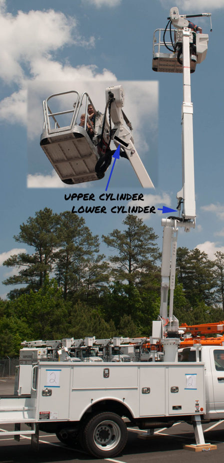
Parallel links are one of the best and easiest ways to maintain level with the ground, but often we just need to keep the same angle.  I once designed a holder for a seam welding robot that needed to keep the tip at a specific angle relative to the part.  It was not horizontal.

The links in a parallel linkage system can be likened to the lines that form a parallelogram. Each corner is a pivot and throughout the motion, the lines will stay parallel. Proper design necessitates that the lengths of non-connecting members are equal.

Same apparatus with the “door” closed
This double set of parallel links allows the sliding “door” to move linearly even though the rest of the mechanism is rotating. All of the red lines will need to be the equal length and the same for the green lines.

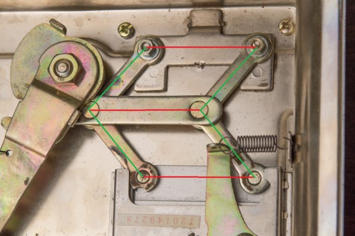
Parallel linkage is probably the most recognizable method of keeping level and the easiest to design.  Two equal length parallel links are hinged to fixed pivot points.  The line drawn between the two pivot points is the line we will remain parallel with as we rotate the links.  Please note that the links do not have to be straight.  They are two force members (like a rope in tension) so if they are not straight (banana shaped), you will have additional moments to calculate.  It is also self-evident that you cannot get continuous rotation with this system because the links will interfere with each other.

There are two main things to consider about designing a system of parallel links.  They are load magnitude and load placement.

The placement of the load has no effect on how hard it is (for the cylinder) to lift up the load.  It seems backwards, but the cylinder is only responsible for lifting the magnitude of the load.  The placement of the load is managed by altering the force in the links.  This is why you often see small cylinders lifting large loads.  Let’s dive deeper into the math.

Figure 1

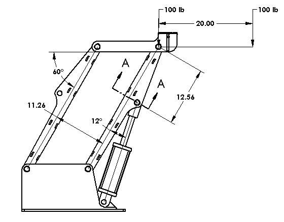
So, I’m going to prove to you that the placement of the load does effect something, but it doesn’t affect our cylinder load.  For my first case, I’m going to put one hundred pounds right over the pin, and calculate the tension in the member left link.  Doing the statics you need to sum the forces at the pin where the load is applied.  The moment is the load (100 lb) times its moment arm (0 in) divided by the distance between the bars (11.26 in).  Anything multiplied by zero is still zero, so there’s no force in that link.  It’s kind of along for the ride and it’s just making sure that the bar maintains level.

I will now move my load out 20 inches and recalculate.  I’ve now got a moment of 100 pounds times 20 inches or 2,000 in-lb.  If I divide that by 11.26 in (distance between the links), my force will be 178 lb.  So, I’ve increased the link load significantly by moving it out 20 inches.  The tension member is very easy to calculate, but the compression member is a little more complicated because of the cylinder.   The statics on the compression link is a little out of the subject so I won’t cover it in this article.  It isn’t too difficult to calculate anyway.

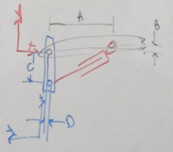
Now let’s move onto the calculation of the cylinder force.  It is largely a function of what the moment is at Section A-A.  This moment is equal to the distance (12.56 in) times the load (100 lb) times the perpendicular angle between the two (60°) which equals 628 in-lb.  Because of the pivot point at the end of the link, there will never be an increase if the load doesn’t increase. 

To say it another way, the shear load in the top member is always 100 lb, but the moment load changes.  We are only concerned with the shear load in this calculation.  (Please note that the moment at A-A will change as the angle changes, so be careful).  With linkage, you can get away with a relatively small cylinder to lift heavy loads because of this principle.

Warning: Load Placement is Critical

You can actually double the loads in a link if you are not careful.  In the example above, I may have a load that centers on the pin and through its travels, the load may actually slide to the left or right.  If we were using this to load baggage onto an airplane, we would have loads that shifted from the center to the edge of the structure.  I mention this because we always want to have the cylinder interface with the compression link and we always want the compression link to stay in compression.

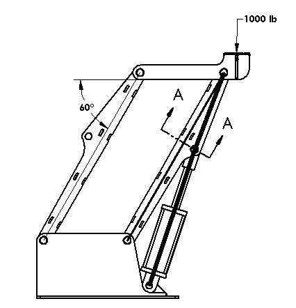
The reason that it matters is simple statics.  Looking at Figure 2, the stress flow is clear.  Our cylinder is in compression (if I remove it, the structure will fall to the right).  As long as the link is in compression, the stress will flow nicely as shown with the thick line.  However, not all of this load will flow through the cylinder (especially as the angle changes) and a small amount will be directed to the link. The point is that we will have a smooth stress flow throughout the link and cylinder.

Figure 2

If I move the load further left of the left link, I will change the direction of force in the right link.  The link with the cylinder is now in tension.  (Note that if the load is between the links, both will be in compression).  Now the cylinder is still in compression as it tries to hold the load up. 

If we look at the modified stress flow in Figure 3, we see that the primary stress flow is between the two pivoting pins and it is in tension.  However, the compressive load of the cylinder needs somewhere to go.  It wants to go up to the top pivot, but there are no forces to balance with.  It then needs to make a U-turn (drastic changes in stress direction are quite awful) and flow back to the lower pivot.  This stress from the lower pivot to the cylinder mount is a tensile stress and will add to the tensile stress of the link. 

Figure 3

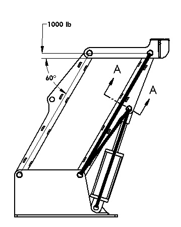
The result of the link being in tension is an amplification in stress.  Also note that stresses don’t like making U-turns.  By definition, it is a large stress concentration and will have you pulling out your hair in FEA (yup, been there).  As a rule of thumb, always try to have your loads biased so that the member of the cylinder is in compression so that your links can be small and effective.  In the rare case where I couldn’t prevent the reversing of loads, I was usually able to minimize the effects by limiting the offset distance and the magnitude of the load.

Conclusion

Parallel links are powerful tools and are used in many different types of machines.  The benefits of using small cylinders to lift loads are self-evident and allow the lifting of heavy objects at longer distances.

Lifting objects is an essential part of engineering.  Keeping them level throughout the lift is a welcomed challenge but can be stressful.  After reading this article you should be able to take initial steps to designing a parallel linkage system. 

Video-Classic Machines: How Does This Cigarette Machine Work?

There are some “old” machines that are just fascinating to see how they work. This is one of them! I am always amazed how complex operations were done in years passed without the use electronic control systems. Let’s explore how this machine works.

How to Easily Design a Hydraulic Leveling System

There are many times in my design career that I needed to translate an object without rotating.  Lifting an object on a table is a great example of this.  At an airport we may see a baggage loader using a scissor lift to load and unload your personal items. 

Hydraulic leveling uses two identical cylinders to maintain level. One cylinder tracks the motion of the apparatus and the other recreated the motion on the other end of the apparatus. This is done by connecting the cylinder bores and rods, respectively, to each other.

There are five main ways to move items without rotation.  They are:

  • Parallel Links
  • Chain and Sprocket Leveling
  • Scissor Lifts
  • Hydraulic Leveling
  • Electronic Leveling

This article will focus on hydraulic leveling which is the most complicated mechanical method of keeping a surface level because there are many components that need to be factored in. One reason that hydraulic leveling is superior, it that it allows the two ends to move relative to each other as in the image below where the boom in the aerial work platform shown below can extend. Parallel links and chain and sprocket are deficient because they cannot change length.

The traditional use is for platform leveling on a man lift.  At the platform, there would be an upper hydraulic cylinder between the platform and the boom.  This cylinder is driven by a similar lower cylinder between the boom and the riser or knuckle. It is important to note that the lower cylinder does not raise and lower the boom, it is there to tell the upper cylinder what to do.

How It Works

Looking at the schematic below, we can see that there are five main components:  The upper and lower cylinder, a load holding valve mounted on the upper cylinder, a dual counterbalance valve (center) and a directional control valve (top).  The directional control valve and dual counterbalance valve are for re-timing, so we will ignore them until later in the article. 

We will illustrate how the system works by going through a cycle:

We will start by having a boom in the lowered position so that the lower cylinder is retracted and the upper cylinder is extended.  When the boom is raised, it will force the lower cylinder to extend.  Oil in the rod section will be forced to leave and travel into the upper cylinder where it will build up pressure and pilot open the counterbalance valve and enter in the rod section there.  Oil from the bore section of the upper cylinder will be forced out and travel to the lower section. 

When we lower the boom, the opposite happens.

To design good hydraulic leveling, you will want to consider six factors:

  1. Cylinder Size
  2. Extra Stroke
  3. Load Holding
  4. Limit Pressure and Fluid Velocity
  5. Account for Deflection
  6. Adjustment

Cylinder Size

The first thing that you will want to do when designing hydraulic leveling is select cylinders with the same geometry. The bore and rod size and the stroke length must be equal.  If there is any difference, you are not going to get good results.

Extra Stroke

It is recommended that you allow for at least ¼” of extra stroke on each end lower cylinder. You don’t want to get into a situation where the boom lift cylinder is not quite all the way extended, but the lower cylinder is extended already.  As you can imagine, the boom lift cylinder is much more powerful and it is going to pull the lower cylinder apart.  Very bad things will happen.  You also want extra stroke so that variations in fabrication don’t stack up and cause problems.  

Load Holding

Hoses occasionally break, so you also want to add on load holding right on the upper cylinder to prevent any unintended motion of the platform. Counterbalance valves with 3:1 or 4.5:1 ratio should do well in this application.  Be sure to set them at least 15% higher than the system pressure.

Limit Pressure and Fluid Velocity

In order to keep these cylinders timed we need to limit the pressure and fluid velocity. We do this so there is not a lot of energy loss when we articulate the boom.

First off, you are going to want to look at the velocity of oil that’s exiting the cylinders and keep it to a velocity of less than 10 feet per second.  This would be the same as you would have for a standard hydraulic return line. 

The reason for this is that you don’t want to have large pressure drops just to move the fluid back and forth between the cylinders.  You want the fluid to do the work of maintaining level and not just trying to get out of a counterbalance fast enough.  Increase your hose size to remedy this. 

Second, keeping your working pressures low is important.  You will want to be working with pressures about 2/3 of the system pressure.  For a 3000 psi system, we will want to have our cylinder operate at 2000 psi.  The reason for this is we don’t want sudden pressure spikes causing the counterbalance valves to open and level to change unintentionally.  As a result, you will need to increase the cylinder bore and stroke length on both cylinders.

Two great resources to aide in your design.

Account for Deflection

This is probably the most overlooked criteria because it is not obvious. In an ideal world, designing the cylinder geometry exactly the same on both ends will work perfectly.  Making geometry the same would require that the dimensions (A, B, C, and D) in the picture here are the same for both the upper and lower cylinders. 

Keep in mind that the rotation of these components can be changed.  Most common in the real world is that booms will deflect.  When the boom is loaded in a horizontal position it may deflect 5° but when it is near vertical, it may only deflect 0.5°.  If we don’t account for that, the platform will not track correctly and be out of level. 

To account for this, the cylinder geometry must cause the platform to rotate 4.5° more than the boom rotates.  This causes the cylinder geometry to be slightly different on each end.

If this is the case in your design, you will want to have the geometry slightly different, but keep the same bore, rod and stroke length in the cylinders.

Manual adjustment

Hydraulic leveling isn’t perfect and from time to time, you will need to adjust the platform level.  In the schematic below, we will need to add a directional control valve for two reasons.  The first is obvious; to occasionally adjust the platform level.  Second, we need a way to prime the cylinders and hoses.  Air is not a friend in any hydraulic system, so getting oil in and air out is important.  Closed systems like this one are difficult to get the air out so I recommend cycling the platform fully when the boom is up and down at least twice.

Direct use of a direction control valve with closed center work ports presents two problems.  First, if there is a pressure spike, flow back to the tank is blocked so the system will need to absorb the excess pressure.  The second reason is that while the schematic shows the ports being blocked, in reality the valve does have small amounts of leakage.  This is due to the valve spool having a small amount of clearance with the hole that was bored in the valve.  While this amount of fluid is small, it is usually measured in drops per minute.  Leaving a unit setup overnight might yield a dramatic change in platform angle.

Placing a dual counterbalance valve in between the directional control valve and cylinder circuit solves both of these problems.  It will make a no-leak seal on the cylinders but also allows for relief from pressure spikes as well as thermal induced pressures.  These counterbalance valves are purely for load holding so using a higher ratio valve is appropriate.  I recommend a 10:1 valve set at 15% higher than the system pressure.

Hydraulic Leveling – Type 2

There is another type of hydraulic leveling where a level switch activates a directional control valve. The level switch can detect when the platform is more than a few degrees out of level and the directional control valve will respond accordingly.  This type of leveling is simple, but very jerky and has a ratcheting effect.  I mention it only to round out the picture because this type of control has been replaced with modern electronic controls.

Conclusion

Lifting objects is an essential part of engineering.  Keeping them level throughout the lift is a welcomed challenge but can be stressful.  After reading this article you should be able to take initial steps to designing a hydraulic leveling system. 

Video-Can You Identify this Unique Stress Pattern? FEA Tip for Holes

Several times in my career, I have come across this very unique stress pattern when dealing with holes that are subject to shear stress. Let’s unpack this and see what causes it and how to fix it.

Video-The Life Lessons that Gertie an Gus Teach Us

Do you feel like you have to choose between Success and Contentment? For many, we may feel trapped in a career that we don’t like or even hate. Are you climbing the corporate ladder only to find out that it is leaning against the wrong building?

The children’s book Gertie and Gus sheds a lot of light on to this subject. Find out how lack of communication and goals gets them in a heap of trouble…

Save 20% Off Most Items! Use Code: 20%OFF
Shop Now