

In part 3 of this series, we set out the plan for our V-belt drive system. We started constructing the system, let’s see how it works.
[aweber listid=6351119 formid=59506199 formtype=webform]
In part 3 of this series, we set out the plan for our V-belt drive system. We started constructing the system, let’s see how it works.
When looking at a hydraulic schematic, it is easy to confuse a blocked port in a directional control valve with a positive load holding device like a check valve.
Directional Control Valves should not be used for holding loads because of hose rupture and valve leakage. In some cases, the work ports can pressurize and this could cause unintended motion. Instead, load holding valves such as pilot operated check or counterbalance valves should be used.
Let’s look at how each situation happens and how a proper load holding valve will fix these problems.
As mentioned, there are multiple reasons that directional control valves (DCV) should not be used to hold loads. Let’s explore what can go wrong.
Hose ruptures happen frequently. Obviously, a this may cause unexpected movement or other consequences. Since most control valves are not mounted directly on the cylinder, there are hoses that lead back to a central control area. Usually there will be multiple directional control valves mounted together.
To mitigate this risk, load holding valves are placed between the DCV and the cylinder or motor. If the machine is designated as “for lifting” where there are people supported by it or able to work under or near it, the load holding valves are required to be placed on the actuator. Hydraulic steel tubing is used to connect the actuator to the load holding valve so that hose rupture cannot occur.
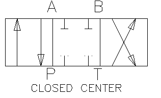
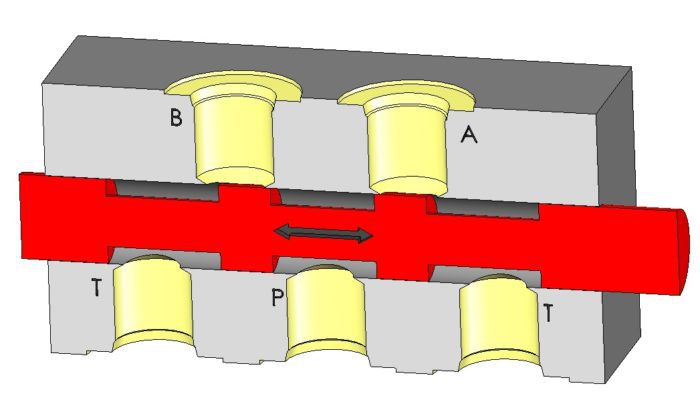
While directional control valves are schematically represented by a blocked “T” shape (see center position to right), the actual construction of the valve is anything but. In the image below, all of the ports are “blocked”, but not really. Let’s look at what is really happening.
From the cross section below, you can see that the gray spool slides in the cavity. The notches on the spool allow fluid to flow from one port to another. As the spool is shifted, flow can flow from P to A and from B to T.
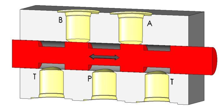
When the valve is in the center position, the loads are mostly blocked. I say mostly because due to the sliding nature of the valve spool. In order for the spool to slide, simple physics tells us it needs to be smaller than the cavity it slides in. So there is a small gap in between the spool and the cavity.
Hydraulic oil can squeeze though these small gaps and leak from the work ports to tank. While this leakage is only drops per minute, over time it can cause a drastic change in motion. This may not have adverse effects in motion over a few minutes, but if you leave it out overnight, you might find that it has moved quite a bit.
On one piece of machinery, we discovered a stuck counterbalance valve when we articulated a cylinder into a load holding position. After break, we found that the cylinder had drifted so that the load was resting on the floor. We were able to troubleshoot this quickly. Since our directional control valve wasn’t designed to hold the load, our symptoms (drift speeds) were amplified, but the problem had the same source.
Another issue with small gaps between the spool and the cavity is that you can pressurize the work ports in the center position. This is only an issue when you have a closed center spool and there is constant pressure on the P port.

What happens is the high pressure P port wants to leak to the lower T port, but before it gets there, it has to tie into the work ports. If we assume that there are similar distances between T, A or B and A or B to P, we would expect the pressure to decrease linearly along the path.
This means that the steady state pressure at the work ports will be roughly half of the pressure port. If we have a 3000 psi standby pressure, we would expect 1500 psi at the work ports eventually. This can move the loads over time.
For all these cases, the remedy is to add load holding valves to system and open or bleed notches to the directional control valve. Let’s see what our options are.
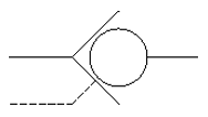
The PO check valve is the simplest load holding valve. It is schematically represented with the symbol to the right. The concept is clear from the diagram. Imagine that it is a tennis ball in a traffic cone. Oil flows from left to right easily by pushing the ball. Flow will be blocked in the opposite direction when the ball is forced further into the cone. If you want to move flow backwards, the dashed pilot line would be the same as sticking your finger into the small end of the cone and moving the tennis ball out of the way.
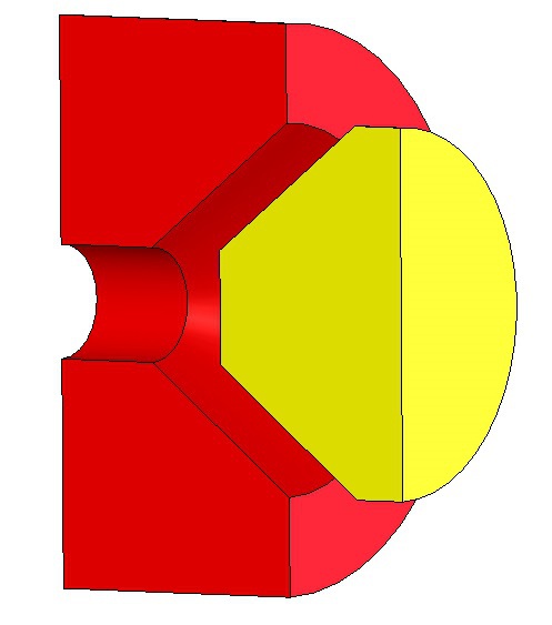
However, if a PO check valve was based on this schematic symbol, it would be extremely unreliable due to manufacturing tolerances. For this reason, poppets are used rather than balls. A poppet would be a matching tapered cone with no point. The nice tapered surface provides a leak proof barrier.
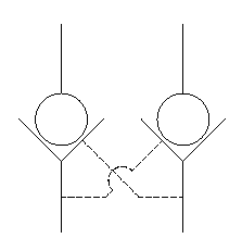
Instead of sticking your finger in the end, the poppet is actually pulled away from the cone using the pilot line.
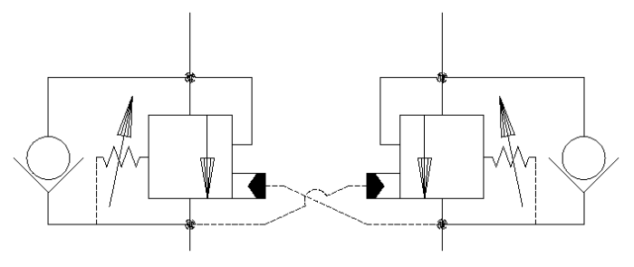
If you are trying to lock a cylinder or motor, you can use a cross ported dual PO check valve. The is combining 2 PO check valves into one block which simplifies the plumbing by reducing two hoses and 4 fittings.
There are two main problems with PO Check valves; they work too well and they don’t control load motion very well.
How can load holding valve work too well? Good question. Well once the PO check valves have locked the cylinder in position, it is LOCKED. Decades ago, this was the standard for load holding and hydraulic cylinders started splitting at the tube seams. In the investigations that followed, it was discovered that temperature played a large role in the failures.
Hydraulic oil is incompressible. If an aerial lift or a crane was set up in the morning, by mid afternoon the oil would heat up and expand. The fluid was trapped in the cylinder by the PO check valve and built pressure. This pressure often got high enough that it would split the cylinder.
This topic is very large and we will only scratch the surface here. Maybe only rub it gently with a finger.
Generally speaking, PO check valves are available in high pilot ratios, usually 5:1 to 40:1. This the ratio of the held pressure (ball side) to the pilot ratio. If I was holding 2000 psi on a 5:1 ratio, I would need to apply 400 psi to see any motion.
Once this is open, the fluid will flow freely across the check valve which can lead to overrun, oscillations and cavitation.
The simplest example of this is a cylinder holding the load of a very large cylinder with a small flow rate. When we want to let the cylinder down, pressure builds and the PO check valve opens. If the flow coming out of the cylinder is greater than the flow out of the pump (make sure to adjust for unequal bore and rod areas), pressure will drop and the check valve will close abruptly. The pressure will build again and open the check valve.
This is a case with overrun leading to a very noticeable oscillation.
So how do we deal with these issues? The solution if counterbalance valves. CB valves have the same fundamental function as a PO check, but with added thermal protection and load handling capabilities. This is because it is a combination of a check valve and a relief valve.
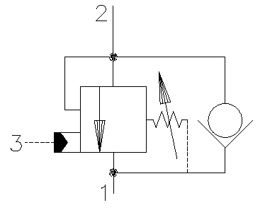
As oil moves from port 1 to 2, it freely flows past the check valve. When the load needs to be held, the fluid cannot go past the relief or check valves. If the pressure at port 2 rises higher than the adjustable spring setting, the valve will open and let oil flow to relieve the pressure. This is the thermal protection. When you want to lower the load, pressure is applied at port 3 to open the relief valve.
The counterbalance valve improves load handling because there are some variations that can be made to the valve. As of this writing, Sun Hydraulics offers 184 different types of counterbalance valves. These variations are mostly different pilot ratio and flow capacities. These variations are possible because the relief valve can be made to fit your needs. To solve the overrun problem above, you would choose a smaller flow rate and pilot ratio. This will meter the flow out of the cylinder, preventing overrun.
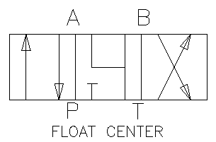
When you add an external load holding valve, it is important to make sure that you aren’t holding the load at the directional control valve as well. If the DCV has closed work ports, you can get strange interactions between the two. One common occurrence is when the counterbalance needs to relieve, but the DCV is blocked. The oil has no where to go.
The solution is to specify a directional control valve with a center position that is “open” or “float”. Many times you don’t want full flow in the center position. In this case you can use a center position that has bleed notches or “motor spools”
Both of these configurations allow a path for oil in the work lines to the tank preventing pressurization and unintended consequences.
There are many reasons not to use directional control valves as load holding valves. Pilot Operated Check and Counterbalance Valves remedy these situations. Just be sure to add an open center position to your DCV to prevent pressurization of the work ports.
Now that we have discussed the drive systems and selected one, how do we proceed? Well, watch and find out.
So we’ve selected using a gas engine to power a cable drive. How do they connect and how do we control that motion?
Find out how we are going to do this.
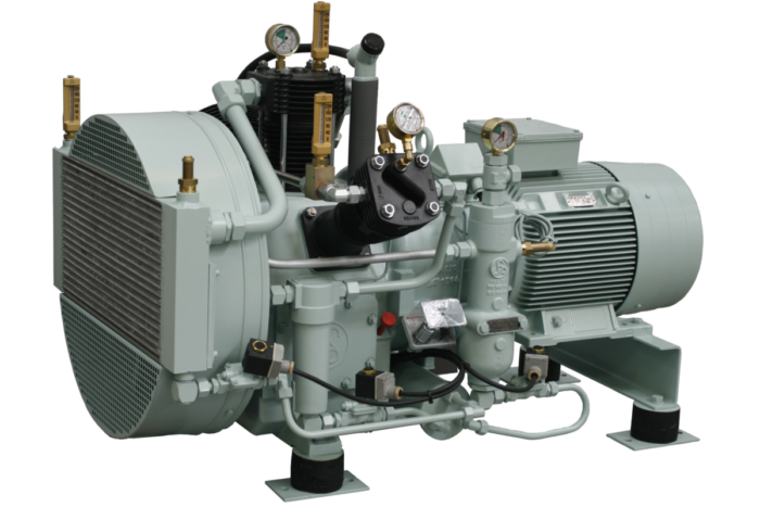
I’m often asked why pneumatic systems operate at much lower pressures than hydraulic systems. There are many benefits to using pneumatic systems especially in the food and medical industries. But there is always the need for larger cylinders and motors due to the low pressures. So why can’t we just turn up the pressure on these systems?
While it is theoretically possible, pneumatic systems are limited to low pressures due to cost, leaking and safety reasons which stem from the compressible nature of air and its reduced viscosity. Compressible fluids, like air, are far more difficult to pressurize than their hydraulic equivalents.
Compressible fluids like air, oxygen and hydrogen have densities that vary with pressure. If I have a pneumatic cylinder filled with air at atmospheric pressure and then start to add weight to the rod, then it will retract and increase the pressure. It retracts because the air molecules are able to get closer together due to the increased pressure.
If we do the experiment again with hydraulic fluid, we will see an increase in pressure when we add the weight, but no change in volume. This is because hydraulic fluid is incompressible.

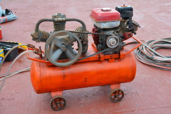
Design engineers need to be able to compute the cost of operation of machines they design. If we look at the power consumption of a hydraulic pump pressurizing 1 cfm (7.5 gpm, 28 lpm) of oil to 3000 psi (207 bar) and a 93% efficiency, it would require 14 hp (10.5 kW). As long as the fluid is doing work, it will remain “cold”.
Theoretically, a screw type air compressor with an efficiency of 65% would require 107 hp (79.9 kW) to do the same amount of work in an iso-thermal process. That is 7.6 times the energy of the equivalent hydraulic system.
It uses a lot more energy to compress air than to pressurize oil. This simply is a function of using a compressible gas rather than a liquid.
Most of that work will be converted to heat in the process. The compressors and tanks will get very hot and will need to have large cooling systems. The cooling system will be very costly due to the increased horsepower requirements
Another complication, that we will expound on shortly, is there will be a need for multiple compressors to step up the pressure to prevent leakage. Unlike the cheap and inexpensive hydraulic gear pump (lots of options for under $200), air compressor stages are more expensive and you can spend a small fortune on an efficient set that meets your needs.
Why can’t we just use hydraulic components? On the surface, swapping out pneumatic valves and cylinders for hydraulic components and increasing the pressure seems like a logical idea. However, these components are designed to work with hydraulic oil and not air.
Air is much less viscous and dense than oil. We know this to be true because we can walk through a room filled with air very easily, but we would struggle to walk through a pool of hydraulic oil.
When looking at a typical hydraulic directional control valve, we have a machined cavity and a spool running inside of it. In the image below, you can see that fluid can flow where the arrows are. As the spool shifts, this is intentional. However, we may want the Ps (Pressure Supply) port blocked in the neutral position.
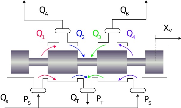
Although it is greatly exaggerated in the image, there is a gap between the gray spool and the bore is slides in. (notice there are no seals between the work ports.) This gap is usually under 0.001″ on a hydraulic valve and special care is taken to make sure this is round, smooth and accurate. There is a fine line between the valve spool sticking and there being too much clearance.
Since there is clearance, you will have hydraulic oil leaking in the valve. Generally, this is able to be measured in drops per minute. If there is designed leakage with hydraulic oil, there will be much more leakage when we run compressed air through it.
Leakage is really just cost. We don’t really care if air “leaks out on to the floor” as my mentor told me. We do care about the mess hydraulic oil makes.
Compressed air leakage is 100% money down the drain, so when you hear air leaking out get it fixed ASAP. The audible leaks are the most expensive and detectable, but most systems have many more smaller but inaudible leaks that can cost your just as much if not more.
Increasing the pressure doesn’t make this get any better.
Directional control valves aren’t the only components subject to increased leakage. Air can leak around seals in compressors, cylinders and rotary motors much easier. A hydraulic cylinder used with compressed air, may need tighter tolerance rods, bore and seals. Extra machining is expensive and the seals will need to be very high end. Of course, this all leads to increased costs in components.
To improve compressor efficiency, you will want to use multiple stages. This keeps the pressure differential relatively small so that there is less force and wear on the piston seals. For example, you might have: the first stage going from 0 to 80 psi; second stage 80-130 psi, and the third stage from 130 to 175 psi. These small jumps allow the the air to be compressed efficiently and even allows the air to cool a little before going to the next stage.
In order to get from 0 psi to 3000 psi, you will need numerous stages to have an efficient design.
The result of trying to use off-the-shelf hydraulic components with compressed air is that you will constantly be chasing leaks in your system.

Unintended motion is one of the largest contributors to machinery related injuries. Anytime equipment moves there is a chance that some part of your body could get smashed or cut off!
It is nearly impossible to use pneumatics for load holding in a de-energized capacity. In a cylinder application, it near impossible to hold it in a certain position without constant position feedback and adjustment. Leakage and changes in temperature, load or pressure will cause motion with the compressible fluid.
While this is a situation that exists with low pressure pneumatics, it will be harder to control and motion will occur more sporadically with higher pressures. With hydraulics, you can add PO check or counterbalance valve and you are set.
Now, let’s address the elephant in the room. Besides leaking air everywhere and it costing a fortune to operate, high pressure pneumatics aren’t used because there is a severe danger from explosion. Likely, there won’t be fire involved, but that compressed air wants to escape and escape fast.
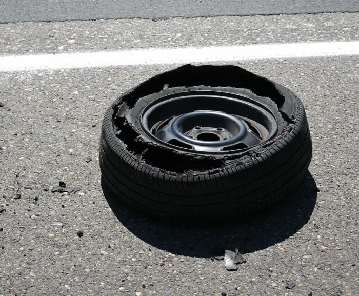
If you have ever seen a car tire rupture under pressure, it is an impressive sight. The tire can tear out very quickly and you can be hit with shrapnel. Keep in mind that most tires are only pressurized between 40 and 120 psi (2.8 to 8.3 bar). We’re talking about going to 3000 psi (207 bar)!
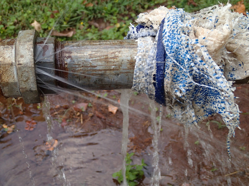
Keep in mind that all the extra energy from our example (107 hp – 14 hp), is stored in the system and is waiting to be released. If there is a rupture in a hydraulic line, you will see oil dribbling on the ground or it spraying at high pressure. With compressed air, you will hear “BOOM” and wonder where the leaking component went. (Beware of the shrapnel)
For this reason, pneumatic systems are usually kept under 100 psi (6.89 bar).
In order to mitigate risk with pneumatic systems, components like pressure vessels are often tested to high pressures before being placed in service. The test is a hydrostatic test, where an incompressible fluid, usually water, is used instead of air. This way, if there is a leak, water will drip on the ground or spray out. If air was used, it would be much more likely to explode.
Another short cut I’ve seen is using plastic PVC pipes to run compressed air to work stations. While the material is much cheaper than steel pipe, it is not safer. I worked at a shop that had PVC pipe and one line was struck and blew out the side of the pipe nearly 7 ft away from the impact. Luckily no one was hurt.
While it is fun to run down the road and wonder if you could increase the pressure in pneumatic systems to that of hydraulics, it just isn’t practical or safe. Pneumatics already is more expensive and prone to leaking. Why would you want to amplify these issues?
Yes, we are going to add a launch to our roller coaster to make it more fun! So how are we going to do that?