

One common task for a design engineer is to design an articulating system. Often this is for lifting objects as is the case with a crane, aerial lift platform or even my log splitter’s jib. Cylinders are a great choice for powering this articulation because they are able to provide large amounts of force in a small package. The task of designing an articulating boom seems daunting, but with the advent of 3D CAD, MathCAD and/or Excel, the job has been simplified.
In order to layout the geometry for an articulating cylinder you will need to determine the articulation range and then lay it our in 3D CAD using a parametric sketch. Create a mathematical model that will calculate to loads and forces needed for the geometry. Finally, select a cylinder and tweak the design.
Let’s investigate each step a little deeper.
Determine what your articulation or reach needs to be
This is by far the most critical step, but it is often overlooked. In order to properly design a system that is robust, you need to have a firm grasp on the reach and height requirements. Loading should also be considered here too. Failure to do this often results in having a machine that needs to be ‘stretched’ to meet customer demands. Stretching a unit is never a fun thing and it leads to a patched design at best or complete rework at worst.
For a single cylinder articulation design, 120° of
articulation is the maximum you want to plan on. The articulation is really pushing it at
125°, but don’t go there unless absolutely necessary. The reason is that 5° more articulation
really cuts down on your moment arm for the cylinder; this requires a larger
cylinder. Another less noticeable
downside is the articulation speed will be really fast at either end, but slow
at mid-cylinder stroke. If you need
articulation greater than 120°, linkage and/or a second cylinder may be
needed. Linkage, sometimes referred to
as ‘four bar linkage’ is a method of improving the articulation angle. Instead of having one end of the cylinder
connected directly to a structure, it will pin with four links. The links are designed such that it will keep
the cylinder far enough away from the boom creating a good moment arm
throughout the articulation. The subject of linkage for articulating designs is
vast and we will need to discuss that in a future article.
Layout the geometry in 3D CAD
The advent of 3D CAD and parametric sketch drawing has made this step a breeze! When I was a young engineer, I once witnessed an older colleague who was laying out a cylinder in AutoCAD. This was a very hard thing for me to watch as he spent the greater portion of a day trying to find favorable cylinder geometry. Since AutoCAD is non-parametric, every change in mounting location or cylinder length lead to multiple move and rotate commands. Having just been trained in Solidworks, I knew that technology would greatly reduce the complexity and time it takes to come up with good cylinder geometry. It was on that day that started developing the method I am sharing now and have been using for fifteen years. In this process we will demonstrate how we can use Solidworks to layout the articulation of our log splitter jib in a fraction of the time.
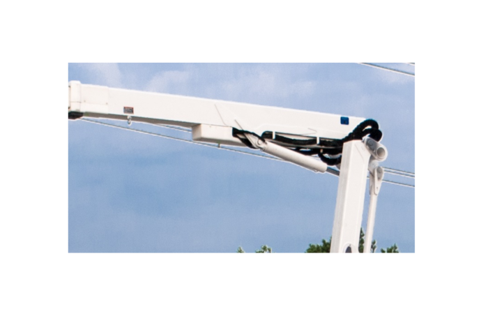
After modeling in our jib support locations, we will make a sketch. Once in sketch mode, we need to determine what our coordinate system should be. Since our jib tube is long, straight and easy to put a level on, I am choosing that as my ‘x’ axis no matter what the jib rotation is. I will then draw a line 39.5” out from the pivot and 2” perpendicular to it. This will mark the location the cylinder attaches.
Next, I will add another collinear line to the 39.5” line that is 14” long and a 4” line perpendicular to it. This is where my load chain will attach.
I will then want to duplicate this four line part of the sketch using equal length, collinear and perpendicular relations as needed, thus creating two positions in the articulation. At this point we can drag these entities into a rough position of where we want the articulation to be.
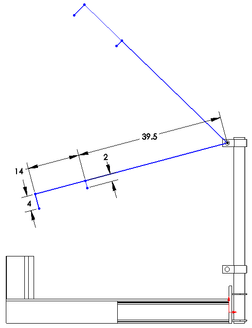
This is where it gets fun! Now we can add the cylinders in. Since a cylinder can be divided into two sections, dead length and stroke; we will draw them as two different lines. The dead length is the retracted length minus the stroke (teal). For most off the shelf cylinders, this dimension ends us being about 10.25”. The larger the cylinder you have, the greater the dead length. The teal lines represent the dead length and there is only one section per cylinder. On the lower articulation, I have one section of stroke (fuscia) and the upper articulation there is two. This will show the cylinder in the fully raised and fully lowered position.
There is a lot of time spent in this step of the process. There are so many variables to change: stroke length, 30 in; dead length, 10.25 in, the cylinder dimensions to the jib pivot, 39.5 in and 2 in. In this example, it is a fixed distance between the jib pivot and the lower cylinder mount, but it doesn’t have to be. In fact there is nothing forcing the cylinder to be mounted directly underneath the pivot either.
When designing geometry in Solidworks, an unsolvable sketch means that your geometry is bad. Reducing cylinder stroke can often rectify the situation. Also, make sure that you are able to stroke the cylinder fully without having to worry about not being in a rest or holder or unintentionally contacting other components.
Calculate the geometry, loads and forces by creating a mathematical model
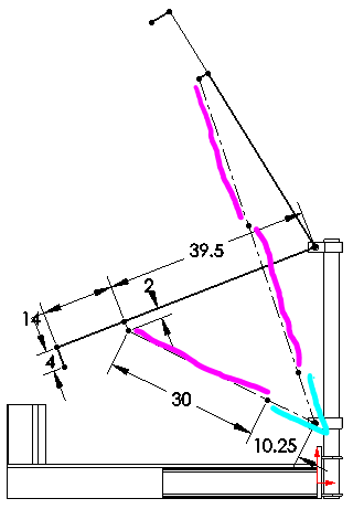
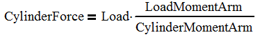
One really cool thing is that we can calculate the force on the cylinder at this point with relative ease. If we add two dimensions, we can learn the cylinder moment arm and the load moment arm.
The highlighted dimensions show the load moment arm, 48.41 in, and the cylinder moment arm, 30.49.
If we assume a load of 1000 lb, our cylinder load will be 1000 * 48.41 / 30.49 or 1588 lb. From here the force on the cylinder is easy to calculate:
If your load is constant, the highest load on the cylinder will either be at the minimum or maximum cylinder stroke. This just happens to be super convenient because that is what we modeled. It is not a coincidence though.
A deeper dive
So in most cases we want to know more than just the cylinder force. Things like the forces on the pivot pin and jib angle are also important. Hydraulic cylinders are generally powered by a constant flow of hydraulic oil. This means that the cylinder will extend at the same rate throughout the stroke and regardless of load on it. However, linear motion powering articulation is never a constant. Knowing the instantaneous change in articulation vs cylinder length is also important. Many times, the articulation can change far too rapidly near the end of the cylinder stroke and the system needs to be redesigned.
In order to calculate these things, we will need to take a deeper dive and use some trigonometry (breathe) to calculate the forces and lengths of all the components. Before we get to that, we need to first determine if we want an articulation based mathematical model or one based on the cylinder stroke. I see benefit both ways, but I generally fall on the side of going with articulation based. This way I can specify and angle and get the exact height and reach.

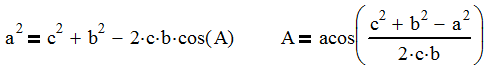
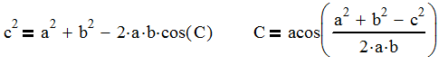
So the image above shows the mathematical representation of our geometry. We will be using the Law of Cosines and Pythagorean Theorem or Rasmussen’s Law (yeah, I proved it and named it after myself). Since we are going to use the Law of Cosines, we will first label the sides a, b, and c and the angles opposite those sides as A, B and C.
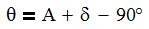
Defining the Articulation Angle
In my example, we will be defining the angle θ as the articulation angle. It is pictured here in the negative as one looking at the log splitter is most likely going to consider this a downward slope. We can quickly define θ as:
Where
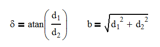
And
It is at this point that you either select to specify the angle (θ) and calculate the cylinder length (Lc or a) or specify the cylinder length and calculate the angle.
One thing to note is if the cylinder didn’t mount directly below the pivot, there would be another angle we would need to either add or subtract from the articulation equation to find θ.
Cylinder Length and Moment Arm
So in a parametric sketch, it is easy to measure the cylinder length and moment arm with a dimension. However in a mathematical model, we just don’t have that luxury. So once again it is trigonometry to the rescue. Using the following equation, we can determine the angle, C.
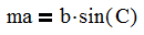
Now we can use the following equation to calculate the moment arm.
It is just that simple to get the information that you want from the model. At this point, we can start looking at the forces on the cylinder and pivot pin.

Calculating the Forces
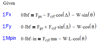
The first thing that needs to happen here is to select a coordinate system. This is a critical decision and can make calculating the forces easy or hard. In this case, I have decided to always have my jib tube be the x-axis. I do this because the angles Δ and θ are both relative to the jib tube as the tube articulates. If I choose the obvious reference frame of the jib support tube being the y-axis, I complicate the angle of the cylinder by having to combine the angles of θ and Δ as well as making the length a function of the angle θ. The other benefit of using the jib tube as the x-axis is if I wanted to operate on a slope, I can add or subtract the slope from θ.
A final note is that we will be ignoring the contribution of the 4” offset where the load attaches. The angle it adds is only 4° and not a significant enough source of error to consider it. We can easily oversize the components here to compensate.
We can now perform statics on the jib tube and develop the three following equations that will specify our pin and cylinder forces:
MathCAD vs Excel
So there are many reasons to choose MathCAD or Excel for doing this analysis. As a result, I usually do both if for no other reason, I can check my work.
The benefits to MathCAD are:
- Visual recognition of the equation and any errors
- Easy identification of logic flow (left to right, top to bottom)
- Use of solve blocks prevents algebraic errors and can solve simultaneous equations.
- Automatic calculation of units
- Quicker time to first results
And the cons are:
- You can only analyze one input at a time
- For lengthy calculations, you will need to input near the top and then scroll to the bottom to see the results. This gets old very quick.
- Difficult to determine information about changes in articulation.
The benefits to Excel are:
- You can calculate many articulations at the same time
- Inputs and outputs can be on the same row, eliminating scrolling
- Charts are added quickly
- Multiple tabs allow for separate areas of calculation and data can be shared with other tabs
And the cons are:
- Equations are difficult to input and troubleshoot
- Difficult to determine logic flow.
- No simultaneous equation solver: an iterative approach may be needed.
- Watch your units (especially degrees). No unit calculation here!
MathCAD Model
Below is a MathCAD mathematical model where the articulation angle is specified and we can determine multiple outputs which are highlighted in yellow. One of the drawbacks to a MathCAD model is we are only able to analyze information one angle at a time. Other than that, it is quite easy to see the flow of logic.

Excel Model

So the first thing that I like to do in Excel is to create a sheet with only constants in it. Here is my list for this project. Under the ‘Formulas’ tab, I can define a name for each variable. When I want to use the variable, after typing ‘=’ in the cell, I can select the variable from the ‘Use in Formula’ command. This is one of the greatest features Excel has added! No longer does the formula look like $D$2*A4, but now it will display the variable name! This is a Godsend for formula troubleshooting.
The next step is to start entering data from our formulas into a different Excel sheet. Here you can see that my articulation angle is the input and the rest of the table is outputs. I basically copied the formulas from MathCAD and in some cases, rearranged the variables to solve for the intended one.
I have also put limits on the cylinder length using conditional formatting. The cell turns red if the cylinder length is less than stroke plus dead length and if it is greater than twice the stroke plus dead length. This is a helpful check to see if the articulation even falls into the range of motion that is intended. In this case, the cylinder has range from about -21° to +59°.

One thing that I love about Excel is that you can calculate and see all the information at the same time. For this reason, I will probably never abandon Excel for calculations of this magnitude. Since I can see all the data, I can produce plots like the one shown below. This is a plot of the articulation angle vs the cylinder length (blue line). I have imposed a linear trend line not only to expose the average rate of change, but also to show that the cylinder length and articulation aren’t proportional to each other.
I have also added the rate of change of the curve (orange) and you can see that as the cylinder length increases, the rate of change decreases. This is a great tool for planning your hydraulic system because it allows you to evaluate where on the curve you are planning to operate. You may find you need reduced flow or a proportional valve to help control the system.

Select a cylinder
Selecting a cylinder is usually as easy as choosing a bore, but sometimes a custom cylinder is needed for things like: load holding, special spacial considerations, position monitoring or different mounting options.
The cylinder in this case has low working pressures, so there isn’t much design work that needs to be done here. However, on larger systems where high loads demand high pressures there is need to not design up to the limits. As a rule of thumb, 94% efficiency can be expected from a cylinder. You should also plan to stay at least 300 psi below your relief valve setting. Relief valves partially open before their setting dumping some flow to tank. We want that relief fully closed in normal operation. If using a compensated valve with load sense functionality, you will want to stay at least 50 psi under the margin or standby pressure.
The reason I say this is from personal experience. Twice in my career I’ve designed a machine where the cylinders just weren’t strong enough to lift the load by just a little bit. A change in geometry was needed for both cases and it lead to smaller articulation and a cylinder redesign for longer stroke. Once your cylinder and structural design is complete and built, it is usually next to impossible to make dramatic increases to performance without going back to square one. I say this because you are less likely to get heat from a cylinder that has more capacity than you need. Error on the side of more cylinder capacity.
Tweak the design
The final step is tweaking. Yes, you can tweak anything to death, but try to set firm limits on your design timeline. Once you have a rough layout, analyze all aspects of your design by asking some of these questions and making up your own.
- Is the height and reach of the articulation meeting my expectations?
- Does this design lift the expected loads?
- Will the cylinder I need fit into this envelope?
- What is my margin between available pressure and cylinder pressure? Do I have enough extra capacity?
- Are the forces of my pins within reason?
- What is the maximum slope that this can operate on? What is the expected roll from suspension?
- Is my rate of change of cylinder length to articulation fairly constant? Do I need to impose hydraulic or electric controls on the system to get the performance I desire?
If you are not satisfied with the answer to any of these questions, go back and tweak. It is so much easier to tweak the design on paper than to wait and see what happens.
Conclusion
This process is a difficult one for any engineer. Fortunately, we live in a time with parametric sketch technology which makes it so much easier to choose the geometry right for your application. Break the process down into the steps mentioned above and it gets simpler! Doing the process in small steps with help you master this process quickly.