

On a recent project, there was a 25 horsepower motor running a torque limited piston pump. When we were doing performance testing, everything worked out fine. As soon as I left, the customer was complaining about excessive heat generation leading to downtime waiting for the oil to cool.
At first, I thought that a relief valve may be set below the compensator pressure, but a quick check showed they were operating correctly. So I did some research.
The problem wasn’t clear until I talked with the pump manufacturer. In order to keep a pressure compensated pump cool, the oil needs to be circulated internally. Depending on the manufacturer, 1/4 of the flow may be dumped back to tank to keep the pump cool.
Pressure compensated hydraulic systems tend to overheat because oil is continually circulated to keep the pump cool. The higher the standby pressure, the more heat created. Adding heat exchangers, shutting the pump down and lowering or having adjustable stand by pressure can reduce the heat generated.
So you have spent the extra money to get a piston pump, but do you know that there is a hidden danger in built in to these pumps? Let’s explore the danger
The Cause of Heat
It turns out that pressure compensated systems are always moving oil, even when in standby. I found out that roughly 3 to 4 gpm were being dumped back to tank through the pump’s case drain at the compensator pressure. This was nearly 7 horsepower that was wasted.
This situation was not detected in testing, because we ran back to back tests with no idle time in between. Once the idle time was added in, we discovered that the oil temperature rose around 1-2 degrees per minute. An impressive feat on 100 gallons of hydraulic oil.
There are several ways to minimize the heat generation with a pressure compensated hydraulic system
- Add a heat exchanger
- Minimize idle time
- Shut the system off
- Lower the compensator pressure
- Adjustable the compensator pressure
Add a Heat Exchanger
Adding a heat exchanger is a very obvious solution. These are usually forced air radiators made for hydraulics that are installed on the return line or the case drain line.
In an industrial application, an 8 hp heat exchanger is going to run around $1000 (in 2019). That doesn’t include the cost of the hoses or an electrican to wire the fans. Mobile (12 VDC) applications are less expensive and easier to wire yourself.
But as an engineer you should be asking yourself, “Why am I generating all this power just to heat the shop? That extra heat is going to make working in the summer excruciating.” All that an it is wasteful as well.
If we assume that we have 7 hp of wasted power from our pump during idle time, that is 5.2 kWh of energy. At 12 cents per kWh, that is $0.63 / hr of idle time.
That is a super expensive waste of energy!
If the only reason you are adding a heat exchanger is to reject idle time heat generation, there are many other options which we will explore below. Don’t let the simplicity of the a heat exchanger solution be where you stop. Keep reading.
Minimize Idle Time
As an engineer, the first step should always be fully diagnosing the root cause and not just masking the symptom. If you notice excessive idle time, make inquiries as to why the machine idles so much. Is an operator waiting on another process? Is it breaktime? They are many reasons for high idle time.
If the idle time can be modified by a process change or other external change, do that. However, don’t let that be your only change. People and processes aren’t perfect so expect those types of changes to occasionally fail.
Shut the System Down
This one is pretty self explanatory. If the system doesn’t need to be on, shut it down. If the system isn’t running, it can’t create heat. In fact, it has the opportunity to reject heat out of the system. Win-win!
One thing that we want to watch out for is turning the motor on and off too much. Motor startup is a significant source of wear on the motor so we want to minimize the number of startups.
Luckily, pressure compensated systems will start in a loaded condition. There should be no (or little) pressure on the outlet and compensator. This means that when starting the motor, it won’t be anywhere near fully loaded. Since there is no pressure, it will take 1-3 seconds for the pump to produce enough pressure to load up the compensator. This will usually be long enough to minimize startup loads on the motor.
If the machine is PLC controlled, adding a timer is easy to do when the machine is idle. This will be a good back up to the case where an operator accidentally leaves the system on when it is break time.
In the machine discussed above, we added a 2 minute timer for periods when there were no outputs given to any function. This was a great protection from heat generation, plus it was a signal to the operator that he or she was taking too long. Yes, it also had the side effect of increased production.
If excessive motor startup is a real concern, you may want to add a restart delay. This is common in HVAC systems where it is common to see a 5 minute ‘compressor delay’. This delay probably adds many hours of life to your HVAC system.
The same can be done with your system. Maybe 5 minutes is excessive, but 30 to 60 seconds may be just enough to lengthen the motor’s life.
Lower the Compensator Pressure
In some hydraulic systems, you just don’t need the system pressure you designed for. As a good designer, you have calculated your pressures and flows for less than what is available. As a result, you can reduce the standby pressure, but only minimally.
I say minimally, because there isn’t a drastic reduction in power with this one. However, you know your machine better than I do, so maybe there is more energy savings here.
Variable Compensator Pressures
This option has many possibilities and the best results for improving effiency. We will explore the basic options:
- Adjustable compensator relief valve
- Multiple preset compensator relief valves
- Dump the flow to tank
Adjustable Compensator Relief Valve
This option is the most expensive and most efficient. By using an electro-proportional relief valve (DO3 P to T relief valve for industrial applications), you can set the compensator pressure for exactly what you need for the current function. As the functions change, the compensator pressure changes.

This is the most expensive option because your PLC system is going to have to output an analog signal (usually 0 – 10VDC) to control the electro-proportional relief valve (also expensive). As a good designer, you will also want a pressure sensor to provide feedback on the system.
However, this system is fully customizable and can act similiar to a load sensing mobile system. Through careful programming, you can tailor your pressure setting to what that function needs at any particular time.
This function would also allow you to gradually change pressures from function to function thus preventing hose jumping.
Be cautious, the programming can get very complicated. It may not seem to be a big deal now, but will cause headaches in years to come when you or others will need to service the machine.
Multiple Preset Compensator Relief Valve
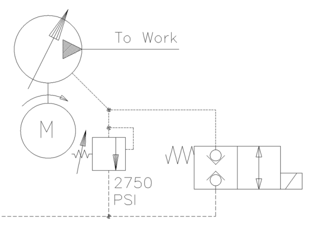
This is a much simpler version of the adjustable compensator option above. In this scenario, we would have one or more compensator relief valves switched on or off by non-proportional solenoid valves.
In this system, there would be one relief valve (main relief below) tied directly to the compensator and other relief valves are separated from the pressure line by 2 position, 2 way, normally closed solenoid operated valve. The main valve must be set at the maximum desired pressure so that if all else fails, the system will have a direct path of pressure control. The other valves can be activated, one at a time, to control the pressure for certain pressures.

This system cost is also reduced from the adjustable relief valve option because it eliminates the needed analog control system and extra programming for the PLC.
Additionally, the system can be made to look quite neat as well. Having a multisection DO3 manifold with the pressure port connected to the compensator will provide the foundation. Often, you can get the main relief valve already incorporated into the manifold which is a big bonus. You can then add solenoid valves on as the first row. On top of those valves you can add the individual relief valves.

If none of the sections are energized, the pump will create the maximum pressure which is set in the manifold relief valve. If one or more sections are activated, the pump will create pressure to the lowest set active pressure. In the schematic above, you can adjust the compensator pressure to 600 psi, 1200 psi, 2200 psi or 2750 psi depending on which sections are activated.
With this setup, you can customize the needed pressure while saving money and preventing heat generation.
Dump the Flow to Tank
This can be a subset of several other options. If your system idles for long periods of time, you can just have a 2 position, 2 way, normally closed solenoid valve dump the pressure to tank. This will destroke the pump and not create any heat.
This is a better option than having the motor turn off because it will reduce the number of starts and stops.
Another option on this is to couple it with a timer so that if there is no demand for the system hydraulics, the solenoid will activate and the pressure will be reduced. When demand for higher pressures is needed, the PLC will deactivate this solenoid.
Which one did I choose?
I actually chose two of these solutions. First, I put a two minute timer on when the system is in normal standby. There is also a 25 minute timer when the system is in the cutting mode. At the 25 minute cycle, only 500 psi is needed to operate a hydraulic motor and control the travel of a saw.

In cutting mode, I also reduced the standby pressure from 2750 psi to 500 psi reducing the needed power by 82%. Sweet! I accomplished this by adding a second compensator relief valve that is activated by a 2 position 3 way valve.
Conclusion
Pressure compensated systems are generally more efficient and with a torque limiter they will give you the best performance of any other hydraulic system. Unfortunately, they do have the drawback of heat generation when in standby mode. If the solutions above are applied, you can often eliminate the need for a heat exchanger.