

Connecting multiple valves together is always a challenge. You want to have individual valve functionality, but not loose sight of the overall system characteristics.
Open center or through center valves need to be connected in series using power beyond porting. Power Beyond allows unused flow to power multiple valve sets downstream. Power beyond also allows the designer to choose which valve sections are more important than another.
In a hydraulic system, there can be multiple operator locations. For example an aerial lift device can have multiple control stations. Generally there is one in the platform and one at the base that controls the boom functions. There can also be multiple stations to deploy the outriggers to prevent the chances of bodily harm by having good line of sight.
Mobile equipment like this is the primary use of a power beyond valve. It allows the operator to work at multiple locations while having the needed functionality.
Another benefit to power beyond systems is that you can change which functions are higher priority by choosing what order they are in the valve. In the aerial platform, we would want functions that move the boom lower priority than those that deploy the outrigger. (You want the outriggers deployed BEFORE you move the boom.)
When connecting multiple valves we need to address an array of topics to have good system design.
- Parallel vs Series Arrangement
- Open vs Closed Center
- Through Center vs Tandem Center
- Why not Tandem Center
- Priority Flow & Metering
Let’s get started
Open vs Closed Center
So the first thing to know is what is the difference is between open center and closed center hydraulic systems. This is identifiable in the hydraulic schematic.
The trick to this is to see if flow can return back to the reservoir when no functions are activated. If it can, the system is open center, and the system is sometimes called a full flow system. Beware, the path back to the reservoir might only be a pilot line and only uses about 1/4 gpm (0.95 lpm)
If the path to tank is clearly blocked, your system is closed centered. This system will either employ a pressure compensated pump or positive displacement pump with an unloader valve to prevent heat generation.
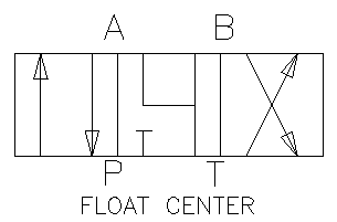
The top image here is a “open” center configuration where all of the ports are connected together. Other open versions of this would include the A and B ports blocked or a “motor” center where the flow is restricted from the work ports.
The image below is a closed center version of the image above. The only difference is the pressure (P) port is blocked so only flow from the work ports can flow to tank.
Open vs Through vs Tandem Center
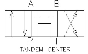
An open (above) and tandem (below) center valve are pretty much the same thing. They allow the flow to move from pressure to tank. The main difference will be in how the work ports are connected.
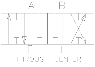
A through center valve allows the flow to run right through the valve when it is in the center position. When the spool is shifted, the the through path will be blocked. Technically, this makes it a 3 position, 6 way valve, but I have never heard it referred to as anything but 3 position, 4 way.
For a non-proportional valve, the flow will be blocked completely usually before pressure can flow to the work port. (it happens so quickly)
A proportional valve will meter the flow so that the opening size from P to the work port will match the opening of the through section. A lot of really smart engineers do CFD (computational fluid dynamics) to make sure that the openings in both cavities are matched for the desired outputs. Takeaway – don’t worry how it happens, just read the technical graphs they provide you.
Valve Cores
You may hear a salesman mention that the valve has a Y core or Z core through section. These are simply indications of how the flow goes around the spool when in the center position. Valve spools are round and have many notches and recesses in them. They also may have multiple tank port connections.
In a Z core configuration, the flow moves around the spool in a Z shape. This means that the pressure moving around the spool will push on only one side of the recesses causing the spool to shift one way due to pressure differential. To resist the spool from moving, heavier springs are used to keep the valve in the center position.
With the heavier springs, the operator may notice that the valve may shift easier one way. It may be a slight drawback.
A Y core configuration solves this problem by splitting the flow (in the shape of a “Y”, gasp) around the recess making the pressure differential to cancel out. This results in a balanced spool and the ability to use smaller centering springs.
Why We Don’t Use Tandem Centers
The problem with tandem center valves is that when multiple valve sections are used. I detailed this problem in another article, but I wanted to do a quick summary here as well.
Pressure Intensification
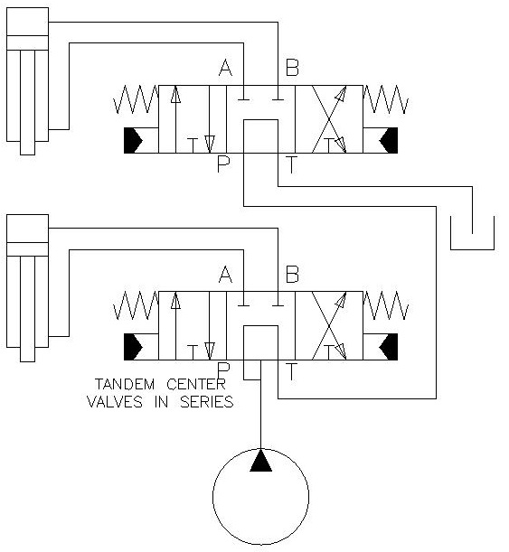
In the below configuration using tandem center valves, you can actually get higher pressures. This can cause damage to components to the structure or worse; bodily harm.
This can happen when the lower directional valve is moved so the P goes to B and A goes to T. Because of the cylinder ratio (bore side area / rod side area), let’s say it is 1.5:1 we can actually build up 1.5 times the system pressure on the A work port. This pressure then goes to the second (top) valve.
Most hydraulic systems don’t have relief valves between the sections so there is no protection on the system. Also, you can intensify the pressure the more sections are in your system.
Other issues are low pressure and a limited supply of oil. Low pressure can occur when the first section is shifted the other way connecting pressure to the A port. Here the cylinder ratio works against us.
Finally, the cylinders only have a limited supply of oil. Once the cylinder is out of stroke, there is no more oil for any of the downstream valves.
Tandem center valves are not the solution for using multiple valves on an open center hydraulic system.
For more information on tandem center valve, please read my article and watch this video.
Through Center Valves
As mentioned previously, adding a path through the center of the valve spool allows much better control off the downstream flow and pressure.
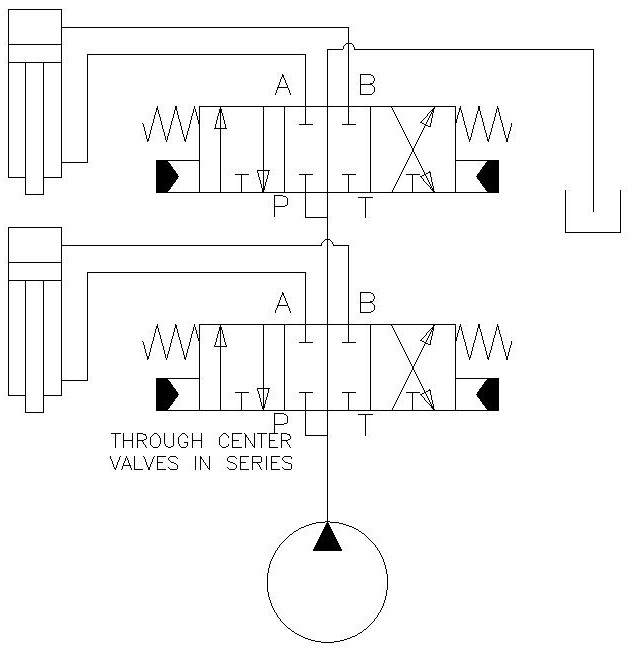
In the figure below, the as the first (bottom) valve is shifted, the flow is cutoff to the second valve. If it is non-proportional, there will be no flow to the next section. If it is proportional, the flow to the next section will be reduced by the amount the valve spool is shifted.
Parallel vs Series Arrangement
Parallel Arrangement
Now that we have defined, open and closed center systems as well as which center sections to use, we need to learn how to combine them.
Most of us have indoor plumbing and we can identify that it is a closed center system. This is because each faucet or appliance is at the end of a branch stopping flow when shutoff. If all of them are shut off, the pressure builds until maximum pressure is built.
Household plumbing is a closed center system and we need to attach all of the faucets in parallel or on their own branch for proper functionality.
Most industrial hydraulic applications work this way where many valves can be added in parallel to the pump pressure.
What Happens If We Add One Open Center Section?
If we were to add only one open center section to our system, none of the closed center valves would function as intended. The system is now an open center system and flow would pass through freely. This changes if the open center valve is blocked and allows pressure to increase.
Below is a good example of how to combine an open and closed valve system. The working valves are closed center, but there is an unloader valve (S7) that is energized only when one of the other valves is energized. This allows us to use an inexpensive gear pump but operate closed center valves.
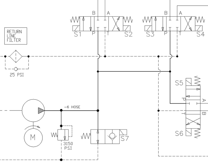
The schematic shows that all oil is blocked at the three directional control valves, but can flow freely to tank if S7 is not energized. Energizing any of the other valves (S1 – S6), will do nothing if S7 is not energized.
Series Arrangement
Looking at the above example, if we were to change all of the closed center directional control valves to open center, you will have multiple paths for the oil to flow. To make the machine do anything, you would need to energize multiple things to get any action.
Action = S7 and (S1 or S2) and (S3 or S4) and (S5 and S6)
This combination is probably not what your desired use of the hydraulic system. Rearranging the valves in series is your solution.
I Thought This Article was About Power Beyond?
It is and we have already introduced the concept with out mentioning it by name. Revisiting the through center schematic from before, the power beyond is the line that connects the two directional control valve.
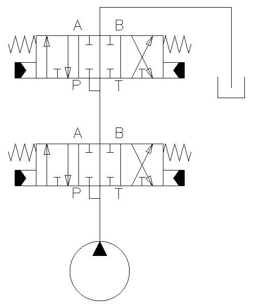
In a tandem valve center, there are only four ports on the valve; pressure, tank, A and B. The through center adds a fifth port; power beyond.
If this was a sectional valve or monoblock valve, the power beyond is handled internally and there is no need for additional porting. However, if you have multiple valves at multiple locations the power beyond requires an additional port.
Every open center valve is made with several, minimum 2 and usually 3 tank ports all sharing the same cavity. Part of the reason is for convenience, but one of these can be used to insert a Power Beyond plug.
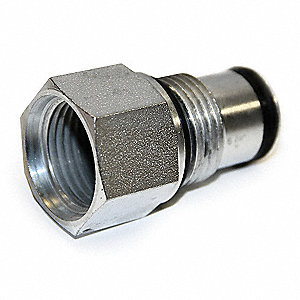
The valve and spools are designed to have the power beyond flow and the tank flow separate and then combine in the tank cavity. The image shows an o-ring the far right side. When screwed into the correct port on the valve, it will divert the power beyond fluid to this port and not to the tank cavity.
This plug gives us high pressure fluid that can power additional downstream valves.
Side note: It is important to not block this port during normal use. It is difficult to relieve the pressure from it.
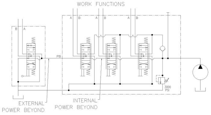
This schematic shows the use of power beyond in between sections and between multiple valves.
Priority Flow
In the schematic above, you can see that the first valve will get all the flow. The remaining valves will only get the remaining flow. If there are many valves, this can lead to unpredictable or no flow for the last valve(s).
This can be both good and bad. It is bad in the way that the flow is unpredictable. It is good in the sense that we can control processes and set priorities in the system.
In the case where there are multiple control stations, we can set the importance of each one. With the aerial lift we could set the priority to be outrigger station(s), lower controls, upper controls. Each one has the ability to override the downstream controls.
A machine with multiple e-stops could also benefit from power beyond. Each emergency stop could divert flow to tank preventing the operator from getting hydraulic pressure and flow necessary to perform work.
Finally, there may be functions that you just don’t want operational while other functions are active. When moving an aerial lift, you may not want the platform to adjust the tilt. The use of power beyond can minimize or eliminate this hazard.
In Summary
The use of power beyond is a wonderful tool to have in your hydraulic belt. It allows the use of multiple valve sections or blocks without the disadvantages of using tandem center valves that plumb the Tank port of one valve to the Pressure port of another.
We also have the advantages of setting priorities in the use of hydraulics for an open center system which allows us to control what functions are available in certain configurations.
Hi Corey I have a towable Excavator (backhoe) and I want to add a hydraulic thumb It is Chinese made my question is do you know if the return end housing has PB capability and if so what is the part number of the diversion sleeve? and Why is there a large plug on the end of the return housing and not beside the T port is that the PB cavity?