Recent Posts

Video-How to Design High Reduction Planetary Gearboxes

Planetary gear sets can be used to do some amazing things. One of which is getting high reduction rates. Let’s see how.

Download Our Planetary Gear Calculator For Free 

Easy to use Excel Based Calculator.  Quickly calculate number of teeth on gears and output speed.  Doesn’t matter what the inputs or outputs are; it’ll calculate it.

We respect your email privacy

Video Transcript

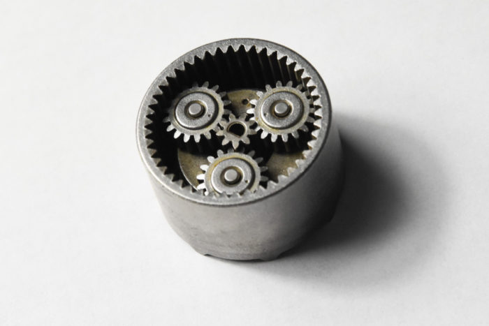
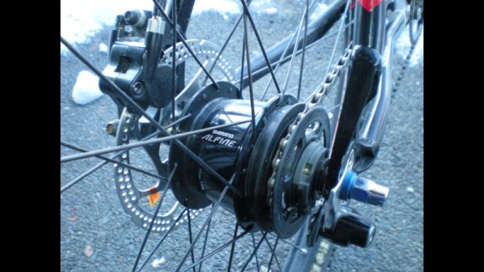
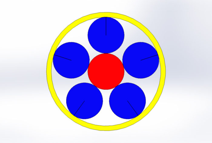
Hi there, Cory with The Mentored Engineer here, wanting to talk to you about planetary gears. Now this will be the second video in our series on planetary gear systems, and we’re going to talk about the general calculations for planetary gear systems and how to get very high rates of reduction in our planetary gear systems. So, let’s review very quickly what a planetary gear system is and how we’re to use it. So, a planetary gear system will contain at least three gears and probably more. We have a sun gear, and we have a planetary gear that goes around the sun.

The ring gear goes around all of these and it’s an internal tooth gear that interacts with the planets. Now we can have one planetary gear, we can have two, three, or probably pretty common numbers. In the example we’re going to do right now, we’re going to have nine planetary gears going around the sun. So, let’s figure out how we do that, but before that, got to do the intro video. Hey, if you like what you see so far, please be sure to smash that like button and subscribe and click that notification bell so I can annoy you at least once a week.

So, let’s get started with the equations. The first thing we’re going to want to know is how all of our gears are related in size. So, if I have a ten tooth sun gear and eight tooth planetary gear, what size does my ring need to be? Good question. We have a very simple equation for determining that.

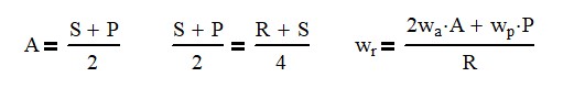
Now, before I show you this equation, I want to say that here, the equation could either represent the number of teeth that a gear has, or it could represent the pitch diameter. Because they’re in relation to each other, it really doesn’t matter. So, in this equation, we can see the size of the sun plus the size of the planet is going to equal to the size that the arm, the carriage arm, is going to turn at. All right, now that’s not a diameter. per se but it is you know

it’s the pitch circle that it’s going to travel at all right and that is also equal to the number of sun teeth plus the number of ring teeth divided by two so we get a nice equation if we know two of the three things we can figure out the rest That’s pretty cool. So, you may also be asking, how many planetary gear sets can I get into my ring and sun gear? And that all depends.

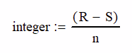
First of all, you have to have the space to put them in. But also, you need to check it with this equation. So, the number of planetary gear teeth needs to be equal to the number of ring teeth minus the number of sun teeth divided by the number of planets that you want in the system. This number has to be an integer. You can’t have a planetary gear with 4.5 teeth.

So, it’s got to have four teeth or five teeth or whatever teeth that it makes sense. All right. Now, as long as it’s an integer, you can keep going up in the number of planets. And every time you go up in the number of planets, hey, you have more meshing ability and you will actually get more available torque out of your system so that’s a cool thing so the final thing we want to know is how all the speeds of the gear system work together there’s a lot of things that are moving or not moving and we need to know exactly what ratios we can expect to get in and out so most likely we’re going to fix one item in our gear system and that could be the ring that could be the sun that could be the carriage those are your three choices really

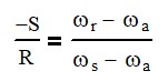
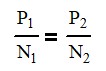
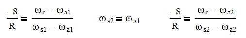
but we want to know how all those things work together and luckily there is a great equation for doing so that equation is the negative number of sun teeth divided by the number of ring teeth, and that’s going to equal the speed of the ring minus the speed of the arm. over the speed of the sun minus the speed of the arm. And this is a great simple equation that helps us out tremendously. Okay, so let’s look at some examples of how, when we hold different things, our speed changes. So, the first one we’re going to do is we’re going to hold the ring fixed and we’re going to turn the arm one revolution.

You can see here that the sun will turn 2.67 times, two and two thirds, what one revolution of the arm does. all right now if we were to reverse this and hold the ring still and then turn the sun the arm would turn three-eighths of a turn, and these are simply inverse of each other. In our last example, we’re going to hold the sun fixed, but then turn the arm one revolution, and we’re going to get 1.6 revolutions out of the ring. If we were to reverse this and put the motion into the ring, and the arm would move 0.625, five-eighths of a turn.

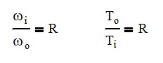
So, let’s talk about underdriven and overdriven. So that’s basically if we input one revolution, we would get more or less than one revolution in the output. So, in the example we just had where the sun was fixed and we inputted to the ring gear, the arm would always move less than what the ring moved. So, in this case, it was one revolution on the ring and five eighths of a revolution on the arm carriage. If we reverse this and input on the arm carriage and output on the ring, we are overdriven now

and we have a 1.6 ratio between the two. So, let’s see how the speed ratios change as we look at a sun gear of 27 teeth, a planetary gear of nine teeth. And if we work the equations out, we find that we have to have 45 teeth on our ring gear. If you think about this, there’s only so big that a sun gear can be compared to a planet compared to a ring that we really can’t get high reduction rates. You know, you’re generally looking, you know, from a quarter of a revolution output compared to one revolution input.

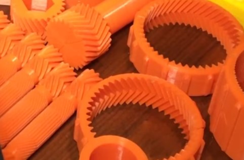
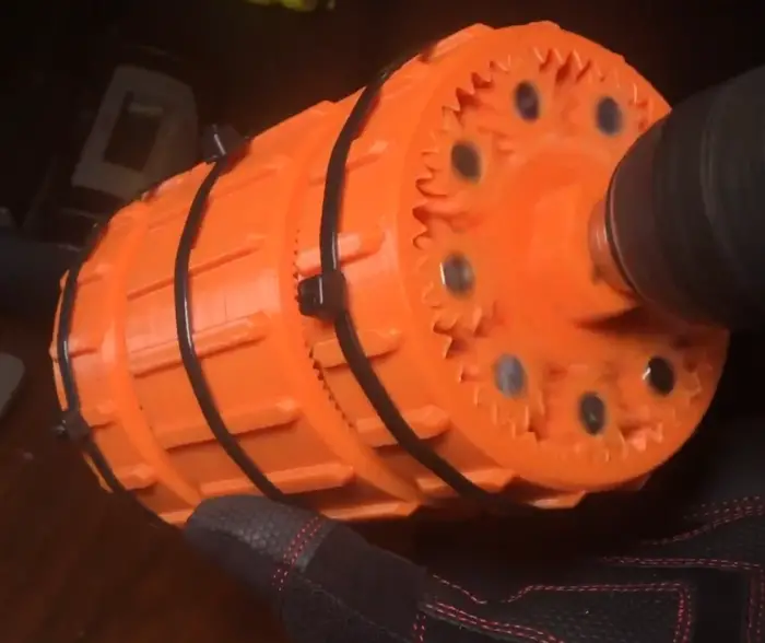
So, four to one ratio dropping down. That’s probably the practical maximum that we can actually get out of a planetary gearbox in one stage. So, if we add multiple sets of planetary gears to our apparatus, we can actually get ridiculously high ratios. So, I’m actually going to show you part of this video where this guy 3D printed a 160 to 1 gear ratio wench and used it to lift an anvil and a couple of tires, and it did it just fine. Hey guys, welcome to Gear Down for What?

Today, I have a special treat for you guys. Introduce yourself to the world’s largest, heaviest, toughest, 160 to 1 3D printed compound planetary gear set. That’s a mouthful. What does it all mean? Let me show you.

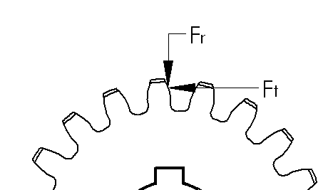
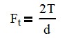
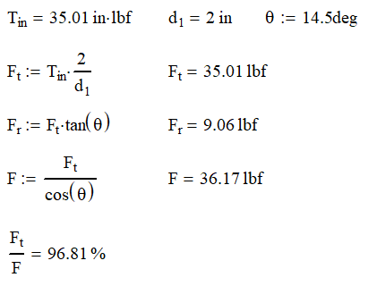
First off, let’s talk about a mechanical advantage. A gear ratio is a mechanical advantage, very similar to how a lever works. Often a lever is used to apply a large force on an object over a very short distance. Okay, so in that, if you look on the first stage where the input is, the sun is turning, and the ring is held fixed, and the sun has 27 gears, and the planets all have nine teeth on each of those gears. And that means that the ring gear has to have 45 teeth from the equation that I used earlier.

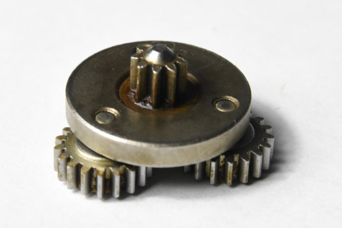
So, what it doesn’t really talk about is that is only a one to… 0.38 ratio. It’s not 160 to 1. What he’s not showing you is that there’s actually gears on all those planets that are turning the internal winch. Now the teeth there are a lot smaller, so I couldn’t actually count the number of teeth that there were on there. and I definitely couldn’t see how many teeth were on the ring gear, which is where the load is actually attached.

So, this is a two-stage planetary gearbox. So, you have a rotating sun, a fixed ring, and then you have the carriage and the planetary gears going around it. That gives us our 1 to 0.38 ratio. of input to output but obviously not 160 to 1. as we look at this first we want to see how many planets can we get in there so if we take our equation the number of teeth in the ring number of teeth in the sun and then divide that by however many planets we want we come up with 18 divided by number of planets and you can see here to get an integer on the output we can have two sets we can have three sets we can have six sets and nine sets and 18 sets, of course.

18, I just don’t see how you get them in there, so we can do nine. In the second set of this planetary gearbox, the rotation of the planet plus its motion in the carriage is actually driving the next set of rings. And we’ll notice that those two motions are in opposite direction. okay so the motion of the planets we normally don’t care about but in this case we do

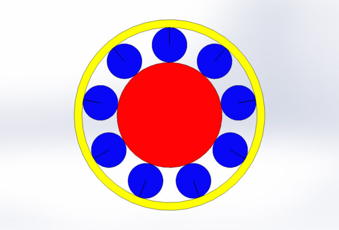
and I actually had to look and actually develop my own equation here for the motion of the planet itself so the motion of the planet is equal to the negative motion of the sun gear times the number of teeth in the sun gear divided by twice the number of teeth in the planet So if we input 160 RPMs on the sun, this will actually give us a ratio of negative 240 RPMs on the planet. So, the reason we want to put 160 RPMs in is so that we know we’re successful when we get one RPM out.

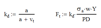
So now we’re going to use another equation to figure out what the motion on the output ring gear is when our carriage and our planets are providing the input. All right, so we’ve got negative 240 RPM of the planets moving and we have 60 RPM of the carriage moving. They’re moving in opposite directions. So, our output speed is going to be equal to two times the speed of our carriage times its pitch diameter, A, plus the speed of rotation of the planetary gears times the number of gears in the planetary. And all this is divided by the number of teeth in the ring gear.

OK, so now before I proceed, I want to mention that we are looking at pitch diameters here and not necessarily the actual number of teeth, because the input teeth on the planetary gear are very big, and the output ones are very small. So, they’re different styles of teeth. They’re different diametric pitches. So just to keep the math simple, we’re going to use 8.81 teeth on the planetary gear and we’re going to have 44.81 teeth on the ring gear. Now, obviously, you can’t have 0.81 of a teeth and actually expect it to work.

You’re going to have to go with a much smaller pitch diameter. So, if we were using, you know, 16 or 12 pitch diameter for the large teeth, we might have to go to 20 or 24, maybe even smaller, 30, 32 for the output one. So just keep that in mind while it’s not going to make sense. So, if we go with 8.81 teeth on the planetary gear, we’re going to have 44.81 teeth on the ring gear. And you notice that the first ring gear was 45 teeth, and this one is 3 16ths of a tooth less.

What’s going to happen is it’s going to take a lot to get that to move. And this is exactly how we get the ratio of 160 to 1. Just look at this animation here of it rotating 40 times on the sun gear to go quarter turn on the output. So that’s exactly how you get large gear reduction ratios when using planetary gears. So, one bit of advice for our friends doing the 3D printed winch here.

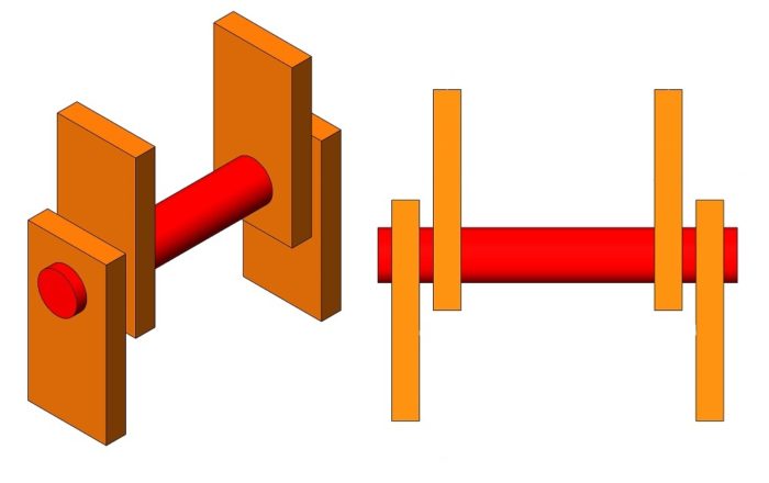
If you’re having problems where the output teeth are slipping on the planetary gears, go ahead and put a sun gear in there so that you don’t have those planetary gears being bent where you got two supports on the outside and then you’ve got the winch pushing down on the inside. If you put a sun gear in there, you now have a balanced shaft because the gears will try to be pushed away, and they’ll be trying to compress that sun. So, a bit of advice for you and stay tuned next time. We are going to talk about doing multiple speed transmissions.

Hey, thank you for watching. Be sure to hit that like button down there if you want to keep good content like this showing up in your inbox. Hey, thank you for watching the Mentored Engineer and have a great day.

Excited to Learn More About Gears? 

Sign up for Mentored Engineer’s FREE Comprehensive Gear Design Master Class ($500 Value) that includes his Planetary Gear Calculator ($250 Value) and weekly Mentored Engineer Newsletter

The Comprehensive Gear Design Master Class is a 17 part series of videos and text where you will learn:

  • How to size gears so they mesh
  • Calculate the stress on the gear teeth
  • Calculate gear ratios in planetary system

After completing this course you will be able to correctly design and spec gear boxes for your applications the first time.

The course and the calculator have a combined value of over $750! for FREE

We respect your email privacy

Video – The Easiest Way to Multiply Large Numbers – Improved Line Multiplication

Multiplying large number is difficult. Any 4th grade math student will tell you that! When you learned how to multiply large numbers, it probably looked a little like this.

This is complicated because larger numbers require you to carry digits over to the next column. (Three times in this case)

There has to be a better way! There is.

How to Easily Calculate Tooth Forces on Spur and Helical Gears

In a gear system it is critically important to understand how much power can be transmitted. The main limitation is usually the gear tooth itself.

Calculating the forces on a gear tooth reduces down to calculating the tangential, radial and axial force on the gear. Then the stress can be calculated on the tooth and a speed factor can be applied for high speed operations. This will ensure long life of your gears.

Spur Gear Forces

The first thing we’re going to do is create a quick free body diagram on a gear tooth. We can make our calculations based on the pitch circle diameter.  We have the tangential force, Ft which is the input force that transmits motion.  We can find the tangential force from the torque on the gear.

Where Ft is the tangential force, T is the applied torque and d is the pitch diameter of the gear.

Excited to Learn More About Gears? 

Sign up for Mentored Engineer’s FREE Comprehensive Gear Design Master Class ($500 Value) that includes his Planetary Gear Calculator ($250 Value) and weekly Mentored Engineer Newsletter

The Comprehensive Gear Design Master Class is a 17 part series of videos and text where you will learn:

  • How to size gears so they mesh
  • Calculate the stress on the gear teeth
  • Calculate gear ratios in planetary system

After completing this course you will be able to correctly design and spec gear boxes for your applications the first time.

The course and the calculator have a combined value of over $750! for FREE

We respect your email privacy

Because of the gear’s pressure angle, we now have a radial force, Fr, that pushes the gears apart.  As you can see, having a higher pressure angle will create higher radial forces.  To maximize efficiency, ball or roller bearings are often used even when rotation speeds may be slow enough to use cylindrical or other non-moving bearings.

By solving for the statics, we can find Fr and the total force F.  The total force is almost a useless number, but it does give some indication of how efficient the system is.  The higher the ratio of Ft/F is, the more efficient the teeth are. 

If have a 14.5° gear with a diameter of 2 in that needs to transmit 35 in-lb, we find that the forces on the gears are as follows:

Helical gears have an added level of complexity not only in design, but also calculation.   

Helical Gear Forces

In the gear above we still have a 14.5° pressure angle, but the teeth are cut at a 18.93° angle from the shaft axis, represented by ψ.  From the diagram below, we slice the gear two ways with θt equal to the gears pressure angle and θn which the pressure angle when viewed from the end of the gear. Now we can start calculating our gear forces.

Since the gear tooth is cut at an angle to the rotation axis, it should be no surprise that we are now going to have an axial component (along the shaft) in our calculation. 

As a result, you will need to think of how you want to deal with this load.  Having a set screw taking this load might be acceptable if you are using small torques, but you will probably need to upgrade to tapered roller bearings or thrust washers if your loads are high. 

Obviously, having the axial component will decrease our overall efficiency of the system as our ratio of tangential force to total force dropped from 97% to 92%. 

One thing to note about changing from our spur gear is that the radial force remains the same.

Calculating the Tooth Force

There is a lot that goes into the design of a gear tooth.  Now I don’t know all the specifics of tooth design and more importantly, I don’t want to burden you with them either.  But somebody has thought this out, done a lot of careful planning and lot of calculation on tooth design.  Let’s leave this subject to the experts and build off their theory, knowing that it works.

Involute Tooth Profile

An Involute Curve

Gear teeth are designed with the unique profile and it’s called an involute profile. The involute profile is made by taking a string and wrapping it around a cylinder.  We then trace the curve of the end of the string as it unwinds.  As you can see, a curve with a constantly increasing radius is made.  This is very similar to the Fibonacci Curve sometimes known as the Golden Spiral. 

The section of the involute curve we use is determined by how close or far away from the center cylinder and how big the cylinder is to begin with. Once again, let’s leave that to the experts and just go on their theory and know that it works.


So, it all comes down to the force and stress exerted on the tooth.  For as complicated as the gear tooth profile is and all the points that the gears contact; the formula is surprisingly simple. 

Those really smart guys that came up with the involute profile; this is where they really earned their money.

Where Ft is the tangential force, σa is the allowable stress, w is the effective width of the gear, Y is the Lewis form factor and PD is the diametric pitch.  As always, watch your units.  For this example, you can stay in pounds and inches.

Lewis Form Factor

The Lewis Form Factor is the real genius of the operation.  This factor takes in all the geometric variances with the involute profile and puts them in a neat little table shown here.  You can see that increasing the number of teeth increases the factor as well as going to a higher pressure angle.

If you want to increase your tooth capability, you can increase your allowable stress, gear width, or use larger or higher pressure angle gears.  You can also decrease the diametric pitch, because fewer teeth per inch means larger (and stronger) teeth.

Barth Speed Factor

The equation above is great for finding the allowable stress for static gear meshing or those running at very low speeds.  Unfortunately, we probably want our gear systems to run at higher speed so we need to add in a factor to account for speed.

Adding the Barth Speed Factor, kd, decreases the allowable tangential force.  The gear speed is the velocity of the teeth at the pitch diameter measured in ft/min.  The constant a is based on gear design and is 600 ft/min for regular gears and 1200 ft/min for precision gears.

Excited to Learn More About Gears? 

Sign up for Mentored Engineer’s FREE Comprehensive Gear Design Master Class ($500 Value) that includes his Planetary Gear Calculator ($250 Value) and weekly Mentored Engineer Newsletter

The Comprehensive Gear Design Master Class is a 17 part series of videos and text where you will learn:

  • How to size gears so they mesh
  • Calculate the stress on the gear teeth
  • Calculate gear ratios in planetary system

After completing this course you will be able to correctly design and spec gear boxes for your applications the first time.

The course and the calculator have a combined value of over $750! for FREE

We respect your email privacy

Example

If we continue the example from above with the gear running a 1800 rpm, we can calculate the Barth Speed Factor.

From there, we can calculate the allowable stress from a 40 tooth, 20 DP 1/2″ wide gear.

From the chart above, we find that a 40 tooth gear with a 14.5° pressure angle will have a Lewis Form Factor, Y, of 0.336. Completing the calculation with give a stress of 5200 psi.

This is minimum yield stress of the material required. This eliminates most plastics and some aluminum gears as options. There are many brass and steel materials that could be used for this application.

What is the Allowable Stress?

With these equations, you should be able to calculate the tangential force.  We are only thing missing is the allowable stress.  Unfortunately, I cannot give an easy answer.  I can only give the lawyer answer: It depends.  Here are some of the factors that will play a role in calculating the allowable stress

  • Hertzian contact stress
  • Gear ratio
  • Material
  • Surface roughness
  • Lubrication
  • Overload
  • Dynamic Load
  • Temperature

Each of these factors can be very hard to determine.  I wish I could be of more help, but every case is different.  My advice to you is this, go conservative!  Calculate the maximum load that system can see and use a design factor or 3:1 on yield stress.  Make sure that your gears are well lubricated as well.  Designing to these criteria will put you on the side of caution.  Remember nobody complains if your gear system lasts forever.

Conclusion

Gear systems are everywhere and fun to design.  Calculating the torque that can be transmitted through gear systems is important in machine design. Fortunately, these calculations are relatively simple and straight forward.

If you want to know more, check out these posts.

How to Achieve High Ratio Planetary Gearboxs

Planetary gearboxes offer three distinct advantages over other gearbox types: high ratios of reduction, higher torque transmission and inline motion transfer.

Achieving high ratio planetary gear boxes is done using multiple gear sets. The speeds of each item are related through the following formula: -S/R = (ωra)/(ωsa).  There are two different methods depending on the torque transmitted and if the desired output is the ring or arm.

Before going further, if you are new to planetary gear sets, you may want to read this article first before continuing to learn how the gear ratios are calculated.

Excited to Learn More About Gears? 

Sign up for Mentored Engineer’s FREE Comprehensive Gear Design Master Class ($500 Value) that includes his Planetary Gear Calculator ($250 Value) and weekly Mentored Engineer Newsletter

The Comprehensive Gear Design Master Class is a 17 part series of videos and text where you will learn:

  • How to size gears so they mesh
  • Calculate the stress on the gear teeth
  • Calculate gear ratios in planetary system

After completing this course you will be able to correctly design and spec gear boxes for your applications the first time.

The course and the calculator have a combined value of over $750! for FREE

We respect your email privacy

Sun Input – Carrier Output

Having the sun as an input and using the carrier as an output is a good way to gain medium ratio gearboxes. In a single planetary gear set, having a 10:1 ratio is around the practical maximum in this configuration.

Download Our Planetary Gear Calculator For Free 

Easy to use Excel Based Calculator.  Quickly calculate number of teeth on gears and output speed.  Doesn’t matter what the inputs or outputs are; it’ll calculate it.

We respect your email privacy

Although higher ratios are possible, the size gets to be really big and it is wiser to use multiple sets of planetary gears to achieve high ratios. If you use two 10:1 gear ration in series where the carrier output of Section 1 is now the sun input to Section 2 a 100:1 ratio is easily achievable.

Let’s look at this drill as an example. Between the motor and the chuck, there is a 36:1 ratio planetary gearbox. Not only does the gearbox increase the torque capacity and allow the motor to turn at its optimal speed, it also provides a mechanism limit torque.

When disassembled, there are two sets of gears using the same ring gear. The sun has 9 teeth, ring 45 teeth and planets 18 teeth. The ring stays locked most of the time. However, when the torque is higher than its desired setting, it will slip causing no motion in the system.

It can slip because there are tabs on the opposite side to the ring that are mated in a track with ball bearings. The track has a spring that presses the ball bearings between the tabs. When the torque exceeds the setting, the spring will compress allowing the balls to pass over the tabs. This allows the ring to rotate.

Using the universal planetary gear equation, we can see that if we input 1 revolution on the sun and hold the ring steady, we get 0.166 revolutions on the output. This is a 6:1 ratio.

Equation 1

When the carrier output is connected to the sun on the next section, we repeat the process and get another 6:1 ratio reduction. We can calculate the entire ratio by using the series of equations below.

The carrier input from Section 1 will power the sun in Section 2

Sun Input – Ring Output

If you want ratios that are even higher, you will need to have a sun input and a ring output. The gearboxes above could utilize the same ring for each gear section. To achieve higher ratios, you would need to have these be different.

In the first section, the ring will be fixed and the sun will be the input, the output will be the planets and not the carrier. In fact, in the example below, there is no planet carrier.

Download Our Planetary Gear Calculator For Free 

Easy to use Excel Based Calculator.  Quickly calculate number of teeth on gears and output speed.  Doesn’t matter what the inputs or outputs are; it’ll calculate it.

We respect your email privacy

In the first section, we will need to use the universal planetary motion equation (eq. 1) to calculate the speed of the arm (important even if there is no carrier). We will also need to calculate the planet motion using equation 2 below.

Equation 2 – Only works with a fixed ring gear

The second section, the planets provide the input and the ring is the output. Here there is no sun gear, although there could be, simply to balance reactive forces between the planets and ring. It is also important to note that the Arm distance must be the same on both sections.

Since the planets are driving, Equation 1 won’t work. We instead need to use Equation 3 to find the ring output motion, wo. From there, we could use Equation 1 to find the speed of the sun in Section 2.

Equation 3 – motion of planets causes output motion of ring

Example: 160:1 Winch Reduction

On YouTube, “Gear Down for What?” made a video where they 3D printed a 160 to 1 winch and used it to lift an obscene amount of weight. I wanted to break that winch down for you and show how the planetary gears used allow for that.

The winch is constructed with three sections of planetary gears. The left and right are the input and have the same gearing. The ring is held stationary because it can be held stationary from a lifting point

The middle section is the output, it has a scallop in it to guide the rope as it winds.

160:1 Planetary https://www.youtube.com/watch?v=ARC0Y1lBliA
Winch with outer sections removed.

We find in the the right and left sections (Section 1), that there are 27 teeth on the sun, 45 teeth on the ring and the 9 planets have 9 teeth each. To illustrate our ratio, we will have the sun input turn at 160 rpm so that we will get 1 rpm out.

If you watch the video, you will notice that these teeth are not cut as spur gears, but as helical gears in a V shape. This gives two advantages. First, the helical gears will run quieter. Second, the V shape allow the planets to stay in place without using a carrier.

These gears are V shaped for self alignment

Using Equation 1, we find that the carrier output is 60 rpm. We can also use Equation 2 to find that the planets will turn -240 rpm.

Using Equations 3 and 4 we can iterate to find the output speed of 1 rpm. It is a little tricky because if we assume the same diametric pitch between Sections 1 and 2, we would need a 8.81… tooth planet and a 44.81… tooth ring to get a 160:1 ratio. It should be obvious that only an integer number of teeth will mesh.

Equation 4

So what do we do?

Scaling for Diametric Pitch Changes

We can see from the picture of the winch that the gear teeth in the center are much smaller than on Section 1 indicating an increase in diametric pitch.

We will need to keep the arm diameter the same in both cases in order to work. We can use the following equation to scale up the diametric pitch and still keep the proper carriage size.

Eq 5

Where P is the gear diametric pitch and N is the number of teeth on the gear. Using equation 4, we can determine A would have 18 teeth. Looking at the picture, I would assume that Section 1 has a diametric pitch of 6.

We can use Equation 5 to determine the number of teeth needed for the carrier arm if we changed to a 32 diametric pitch. Using cross multiplication, we would find that the carrier would have 96 teeth.

Using the three equations below, we can have wr = 1 revolution and then solve for S, P and R. Here we would find that R = 239, S = 145 and P = 47.

Since I’m guessing at what the diametric pitch that these guys are using, these numbers may not be accurate and there may be other options to get you close to a 160:1 ratio. I found that using an Arm of 47 got you to a 156:1 ratio but you will not find gears on a shelf with that diametric pitch.

Conclusions

Planetary gears offer a variety of methods to achieve high reduction ratios using very few gears. This allows for high torque transmission and the ability of a relatively small motor lifting heavy weights.

The calculations shown here are can be used in multiple ways to determine exactly what any part of the system is doing.

*Feature image courtesy of “Gear Down for What?” video on a 160:1 planetary gear set.

How to Easily Calculate Gear Ratios in Planetary Systems

Planetary gear systems can be intimidating to understand. There are so many types of motions and reductions possible that it can be overwhelming.

The motion of planetary gear systems is expressed clearly in the Plantetary Train Equation: -S/R = (ωra)/(ωsa). Once this is known, the speeds of the carrier arm, sun and/or ring can be calculated. Multiple series of planetary gear systems can be used to get multiple speeds and directions.

Planetary gear systems are used everywhere. Some examples are:

  • Automatic transmissions
  • Internal bicycle gearboxes
  • Pencil sharpeners (I bet you didn’t see this one coming)
  • Winches
  • Hand drills
  • Camera lens focusing
  • Truck differentials

Download Our Planetary Gear Calculator For Free 

Easy to use Excel Based Calculator.  Quickly calculate number of teeth on gears and output speed.  Doesn’t matter what the inputs or outputs are; it’ll calculate it.

We respect your email privacy

Planetary gear systems are primarily used for one or more of the following reasons:

  1. Reverse Motion
  2. Transmit more torque than one gear set will allow
  3. High reduction rates
  4. Use with other sets for multiple speeds
  5. Input and output need to be coaxial

Planetary Gear System Components

Planetary gears sets have 4 major components: sun, planet(s), ring and the carrier or arm. The planets are assembled onto the arm. The planets mesh with the sun and the arm rotates around and on the same center line of the sun. The planets also mesh with the ring gear.

Excited to Learn More About Gears? 

Sign up for Mentored Engineer’s FREE Comprehensive Gear Design Master Class ($500 Value) that includes his Planetary Gear Calculator ($250 Value) and weekly Mentored Engineer Newsletter

The Comprehensive Gear Design Master Class is a 17 part series of videos and text where you will learn:

  • How to size gears so they mesh
  • Calculate the stress on the gear teeth
  • Calculate gear ratios in planetary system

After completing this course you will be able to correctly design and spec gear boxes for your applications the first time.

The course and the calculator have a combined value of over $750! for FREE

We respect your email privacy

Generally, either the arm, ring or sun will be fixed in rotation so predicatable motion will occur. In rare cases, the input and output are linked together so that there is no relative motion between the sun, ring and planets. Automobile transmissions use multiple systems and sometimes the sun and the ring will turn to provide power to the arm.

Sizing the Gears

It is important to size each of the gears so that they fit properly. There are two simple formulas that will help you choose the right gears.

First off, all of the gears must have the same diametric pitch in order to mesh. Next, the following equation will relate the number of teeth on the sun, ring and planet. The variables could also represent the pitch circle of the gears, but most use the number of teeth to quickly evaluate if the meshing will work.

S – Sun, R – Ring, P – Planet, A – Arm

For example, if your sun gear needs 17.5 teeth from the calculation above, your system won’t work because teeth always need to be an integer. This is a little more difficult to see when using the pitch circle of the gear.

Calculating the Number of Planets

One of the main reasons to use planetary gear systems is to increase total torque. Every planet in the system adds a new path for force to flow. So where you may be limited by tooth strength, adding planets will allow you transmit the torque through multiple teeth. Genius!

Another benefit of having at least 2 planets is that it will balance the radial forces (force pushing the gears apart) on the shafts leading to smaller shaft designs.

A system where S = 15, R = 45 can only support 5 planets.

The number of planets for an system is limited first by the space available for the planets to occupy. A system with a small sun and large ring will have less planets even though there is more space available than a system where the ring is only 50% larger than the sun.

The other limiting factor is the teeth meshing properly. This can be determined by the following equation.

n is the number of
planetary gears

The result of this equation must be an integer for proper meshing.

A system where S = 27, R = 45 can support 9 planets.

The top example has an R – S of 30 where there could be 1, 2, 3, 5, 6, etc. planets We find out that the spacial constraint is 5 planets.

Similarly, the second example has a R – S value of 18 leading to 1, 2, 3, 6, 9 and 18 planets. This design can support 9 planets.

Calculating Motion of the Components

Generally speaking, we care about the motion of the carrier arm, the sun and the ring. Usually, one of those will be fixed, but there are many times that they may all be moving. Automatic car transmissions are a great example of this. The following equation relates all the components together.

Where S is the number of teeth on the Sun, R is the teeth on the Ring, ωr is the speed of the ring (usually rpm), ωa is the speed of the arm and ωs is the speed of the sun.

For example if we take the second example up there with R = 45, S = 27, P = 9 we can find out the relationships:

FixedInput (1 rev)Output (rev)
RingSunArm 0.38
RingArmSun 2.67
SunArmRing 1.60
SunRingArm 0.62
ArmRingSun -1.66
ArmSunRing -0.60

Multiple Planetary Sets

You can also apply this in steps to get multiple reductions. For example consider the reduction a drill I recently disassembled. (R – 45, S – 9, P – 18) There are two stages in the reduction, where the arm on the first section drives the sun on the next section.

The carrier of Section 1 drives the sun of Section 2

In the drill, the ring is held fixed except when the torque is greater than the desired setting. At this point, the ring will slip and no output motion will occur.

To calculate the output speed, we will need to use the equations below. It is the universal equation used twice and the speed of the first section’s arm is set equal to the second section’s sun

Since the gears have the same number of teeth in the first and second sections, we will have the same reduction in each section which is 1 : 1/6 (input/output) or 6 input revolutions to 1 output revolution. When both sections are combined the ratio multiplies to 1 : 1 / 36 or 36 : 1. Gearbox ratios are commonly referred to as input to output revolutions.

Assembled Section 1 side of planetary gearbox

Calculating Torque

This 36:1 ratio gives a tremendous mechanical advantage because it allows the use of a small and fast electric motor to have tremendous torque on the output.

The ratio of input to output (N) is 36:1 for the drill. The relationship of speed and torque can be calculated using the following equations:

As in normal gear equations, as speed decreases, the torque increases. With normal spur gears, you can only transmit torque through one set of meshing teeth. However, you can multiply the available torque by the number of planets in the system. This is provided that the gears and other components involved have a high level of precision.

Download Our Planetary Gear Calculator For Free 

Easy to use Excel Based Calculator.  Quickly calculate number of teeth on gears and output speed.  Doesn’t matter what the inputs or outputs are; it’ll calculate it.

We respect your email privacy

Conclusion

Planetary gear systems can be intimidating, especially if there are multiple sets. Break them down into smaller sets and tackle them one at a time. Count all the gear teeth and then run the equations to confirm that you counted correctly. These systems can be simplified greatly with just a little analysis.

For Further Study

If you want know more about gear system designs, read the article below. To calculate the torque that a gear can transmit, the section on gear tooth forces begins about half way through.

How to Use Gears – What You Really Need to Know

How to Achieve High Ratio Planetary Gearboxs

All Gear Articles and Videos

Introduction to Planetary Gears

How to Easily Align Holes: 6 Methods

We’ve all been there trying to put together equipment and we can’t get the holes to line up to assemble our pin. Ugh! I’m a hands on kind of guy so I was constantly down in the shop watching and learning how people assembled equipment. (I helped too.)

These tricks will help you assemble large objects faster: design the joint to only pin up two separate components, test fit the pin through all of the components, only align one side at a time, use a long pry bar, use manual lift controls, and use alignment “bullets”.

Alignment is difficult with two large weldments

Let’s face it; assembling components can be frustrating! For small and medium sized components, they can generally be man-handled into place. Common tools for this is a #2 screwdriver and an overhead crane. It gets a lot more complicated when you are tying to assemble two 1000 lb (450 kg) components.

Far too often, I have seen composite cylindrical bearings (i.e. Garmax) tear our the wear surface because of pin misalignment. This is wasteful and preventable because you have to disassemble, cut out and replace the bearing. Time, money and inventory. Good preparation can prevent this from occurring.

As good design engineers, you need to foresee how your creation will be assembled. I’ve learned some tricks over the years. Let’s explore those together.

1. Design the Joint to Only Pin Up Two Separate Components

Image Courtesy of Mid-Atlantic Waste Systems

While this is not an assembly tip, it is critically important. Its one of the things that separates good engineers from the bad ones. The only thing worse than having to align two large items is aligning 3. And worse than that….

Many times, three things need to pivot on the same axis. Using hollow pins can avoid this complication.

The street sweeper shown has three large weldments that come together at the top right of the scissor lift: the scissor arm, the top horizontal component of the scissor and the hopper.

This would be very tough to align all three components at once especially since the hopper would get in the way of supporting the horizontal weldment with a crane.

To me, it would make sense to have a hollow pin connect the horizontal member and the scissor arms. Once that is pinned together, run a normal pin through the hollow pin to connect the hopper.

This simple design change makes it so that we are only pinning together two items at a time.

2. Test Fit the Pin Through All of the Components

This is a duh thing, but often overlooked. Before trying to fit up multiple objects, make sure the pin goes through each one individually.

If it doesn’t go through one, it won’t go through all of them.

3. Only Align One Side at a Time

When assembling two components, like the joint shown below, it is nearly impossible to align both sides a once. So don’t try! Align the side that the pin is inserted on as best you can.

Then insert the pin so that it is through the first component and partially through the second. At some point, you will feel that the misalignment grows and it is harder to hammer the pin in.

Typical Joint of a Stick Boom Crane Pivot

Now align the other side as best you can and continue driving the pin. Do a final check of alignment when the pin is about to go through the final tang of the joint.

This can be done seamlessly if there are two people. One to align and one to drive the pin. (I always liked to hammer the pin: it was a way to vent frustration and it made me look like less of a wuss to the assemblers.)

4. Use a Long Pry bar

Remember that you are the softest thing in the shop! Never stick your hands in a hole to align them. I have seen parts move suddenly. Once I saw a screwdriver sheared off. Keep those fingers away.

Can be purchased on Amazon

Many times, simply using a pry bar can get you where you need to be for proper alignment. However, be careful and cautious with this. These weldments are heavy and will require much force. I’ve personally had the pry bar slip and ended up on the ground.

This is also useful tool to have if there are machinery bushings that need to be installed.

Under no circumstance should the pry bar contact any bearing or machined surface. It will leave a mark or destroy the bearing.

5. Use Manual Lift Controls

Most assembly work is done with the aid of overhead cranes. The most common styles are jib or gantry cranes. Typically, these are electrically controlled with a wired pendant (although wireless is becoming more common).

The major drawback of electrically controlled cranes is they have minimal fine tuning. This means that every time the button is pressed, it will move and probably more than you would like. Typical accuracy is around 1/4″ (6 mm)

chain hoist
Image courtesy of Knock Out Engines

The assemblers I’ve worked with came up with a system where he would tap the controller repeatedly until it would move. The taps would start off weak and build until the bare minimum of motion occurred. This is when the pry bars usually came out. This was more precise and you could move the crane in 1/16″ to 1/8″ (1.6 to 3.1 mm) increments

This works, but there has to be a better way.

There is! Suspend a hand powered chain hoist from your existing overhead crane system.

This allows you to fine tune placement of your items to be assembled. No repeated pressing of buttons and overshooting the hole! When done, you could simply store the hand chain hoist out of the way.

A 1 ton chain hoist, like what is shown, weighs between 20 lb and 25 lb. You can get them in multiple lengths and in capacities up to 5 ton (maybe even more).

You can save some weight in the hoist by removing all but 1 – 2 feet of the lifting chain because we can use the overhead cranes to do the coarse alignment, and then the hand chain hoist to move it only a few inches at most.

Sadly, no matter how many times I suggested this, I could never convince a supervisor to even try this idea. Its a shame. It would have saved them a lot of time.

6. Use Alignment ‘Bullets’

We can all realize that a sharp edges on the end of a pin doesn’t allow for easy assembly.  Most pin designs utilize a small 45° chamfer at the end.  

These are easy to manufacturer and relatively easy to install.  Having a small chamfer allows for a shorter overall length pin.  Where possible, I recommend a 30° chamfer with a fillet on each edge. When used with fiber backed bearings, this will prevent tear out in the event of misalignment at install. Modern CNC equipment can handle this difficult shape with little programming.

If the overall length doesn’t allow for the longer chamfer or you want to allow for a lot of misalignment at assembly, try using a “bullet”.  Named for its shape, a bullet is a temporary tool used to insert the pin and then removed. 

The bullet will have the 30° chamfer (or less) with fillets and simply bolts into the holes used to mount the cookie retention plate. The bullet can be made to any length and shape. If desired, it could taper tremendously allowing for lots of misalignment and easy assembly.

When the pin is installed, remove the bullet and secure the end of the pin. The bullet is reused time and time again. For longer life of your bullet, make it out of a material that can be hardened and induction harden it once you’ve proven the shape works.

Conclusion

You’ve spent a lot of time designing and machining tight tolerances for holes. Your assemblers are all too happy to pull out a flapper wheel to make that pin go in just a little easier.

Make sure that those who assemble your design are equipped with what they need to assemble your creation the way you intend.

Give them the tools they need to do it right. It will save them time and prevent bearings from being destroyed. All this saves the company money.

Save 20% Off Most Items! Use Code: 20%OFF
Shop Now