I can remember it clearly; my older brother got a Lego Technics set for his birthday and I saw gears for the first time! I wanted to play with them so badly that I stole a few when he wasn’t looking. I got caught.
Lego has simplfied the gear selection process greatly so when you want to use your own real world system, it is a bit more complex and there are a lot of choices to make.
Gears transmit power between shafts and the two main purposes are to change speed and direction. In order to use gears properly, matching diametric pitch and pressure angles must be used. Lubrication and proper backlash adjustment are important to ensure long life.
Let’s take a look into the 7 questions that need to be answered to properly use gears.
- What type of gears do I need?
- How will it mount on a shaft?
- What is a pressure angle and which one do I want?
- How do I choose the diametric pitch?
- How do I calculate gear speeds and forces?
- How do I lubricate my gears?
- How do I make sure my gears aren’t too sloppy?
Gears vs Sprockets
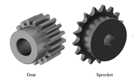
So, the first thing I want to mention is gears are not sprockets and sprockets are not gears. Gears are meshed with other gears. When a standard set of gears are meshed, they will turn in opposite directions. Sprockets on the other hand are connected by roller chains and will turn in the same direction. Sprockets go with chains and gears mesh with each other. The images below show how the tooth profiles are different as well.
What type of gears do I need?
Spur gears
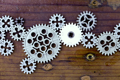
Spur gears are the most common type of gear. They are easy to produce and widely available in a multitude of materials. For those of you familiar with Legos their most common gears are spur gears in eight tooth, a sixteen tooth, a twenty-four tooth, and forty tooth.
They all will work together with each other because they all have the same diametrical pitch and pressure angle which allows the gears to mesh with each other (more on that later). All gears have the same diametrical pitch and pressure angle in the Lego universe.
Small gears are sometimes called pinion gears or just pinions. They usually refer to a gear that drives a larger gear.
The biggest indicator of a spur gear is the tooth is completely parallel with the shaft axis. These have the best efficiency of all gear types since meshing gears won’t create side forces. They also have a ‘line contact’ indicating that the entire face of the gear should be contacting the other gear. A downside is that since the gears are always contacting and releasing each other, they tend to be noisy at higher speeds.
Rack gears
Rack gears are a version of a spur gear that has essentially been cut and flattened out and it has the same diametrical pitch as a round gear, except rack gears don’t have diameter, so they’ve kind of fudged that a little bit and they just keep the same diametrical pitch. If that confuses you, think that it is only a section of a gear with an infinite radius.
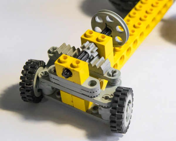
If you’ve ever heard of rack and pinion steering, it is describing a rack gear being moved side to side by a pinion gear. In the picture below, we have modeled the front end of a car and you can see the small pinion gear and the rack attached to the steering arms. The arms are attached to the front axles. When I turn the steering wheel, the pinion turns and shifts the rack from side to side. Pretty simple.
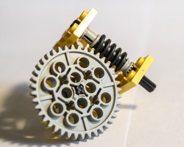
Worm Gears
Another gear type is a worm gear where the teeth are wrapped around the axis of the shaft. It meshes with a more standard gear at a 90-degree angle. This more standard gear usually has a slight angle to match the advancement of the work. Generally, the larger gear is the driven gear and the worm gear is the driving gear. As we turn the worm gear, we only get one tooth advancement for one revolution on the input. Now depending on how you design this you can get great interface between the two gears so that you’re not just wearing on one tooth. You can see that many teeth on either end of the worm gear don’t get any wear.
Worm gears are mostly self-locking at about a 15:1 ratio but that is also dependent of gear lubrication and friction in the bearings.
Worm gears don’t have to be single indexing system; meaning that there is only one set of teeth going around it. Other possibilities are double or even triple indexing threads. When I was in high school, I got to tour the Statue of Liberty. Inside the statue, there is a double helical stairway. This stairway allowed a path for people going up and one for people going down. (It was really steep too.) This is the same for a double indexing worm gear, I went around once, but actually advanced two staircases high.
Worm gears are most prevalent in winch applications where you don’t want the spur to move unless driven. You can also improve braking, by adding a brake. The brake is usually removed when hydraulic pressure is applied. Another application would be crane rotation.
So, the spur gear that interfaces with the worm gears actually has different in profile. If I turn the gear so that the axis is 90° to me, the teeth won’t be flat. They will have a slight scallop to them to match the worm gear. This gives better contact area which decreases wear.
Mitered or Beveled Gears
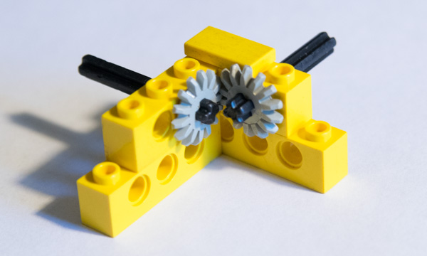
Mitered and Beveled gears have the teeth cut on about a 45-degree angle to the axis of the shaft, and that’s so that you can interface with two of them and form a 90-degree angle. Now you can change the direction from being in the same axis to them being 90 degrees apart.
There is a difference between beveled and mitered gears. Beveled gears are shaped differently that mitered gears making them a better choice in the transmission of motion and not power. As a result, they work well with different gears with differing number of teeth. They are also quieter because the contact is changed from a line contact to a ‘point contact.’
Miter gears on the other hand are intended to only mesh with gears of the same number of teeth and that leads to a line contact situation again. As a result, efficiency increases.
Cog Gears
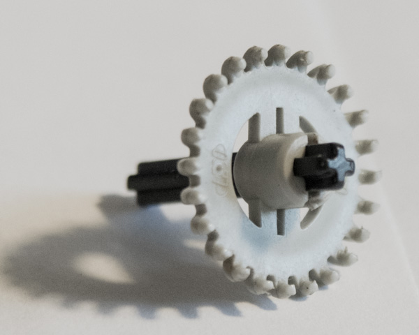
Cog gears have all but disappeared from the industrial world. It is mostly a slang term now for gear. Back in medieval times, it was very hard to shape a gear tooth, so they used a mostly square tooth and slot design. This was great at transmitting motion, but very inefficient for transmitting torque. These have pretty have been totally replaced by a spur gear. The picture here shows the Lego version of the cog gear. The tooth design on it is very crude, but Lego keeps the design because there are a number of ways to transmit motion with it. However, because of the large cuts between teeth, it is not recommended for power transmission.
Helical Gears

The major downside to spur gears is that when you get up to high speeds, they start making noises when they interface with each other. If you have a manual transmission car, you may have noticed when you are in reverse there’s a whine. That happens because the reverse position activates a set of spur gears. So why are the other gears in my transmission so quiet? The answer is they use helical gears.
A helical gear is like a spur gear, but the tooth is cut on an angle that somewhat wraps around the gear. The lack of noise is caused by the line contact of a spur gear being replaced by a point contact. As the gears mesh, there is always a shifting in contact across the face of the gear tooth. Because the teeth are wrapped around the gear, multiple teeth will be meshing at the same time but at different places across the face of the gear.
How will it mount on a shaft?
The short answer is keyed shafts. By far any off the shelf gear with be available in a variety of bores sized with keys slots. You can also buy them with unfinished bores and either cut your own keyway or cut an involute spline.
When selecting a bore size, make sure that you aren’t selecting a shaft that is too big for the for the gear. Recently, I had a system that used a 10-tooth sprocket on a 1” shaft. The system had some pressure spikes in it at startup and actually cracked the sprocket in half. It was able to do this so easily because the material between the outside of the hub and the keyway was only 1/8” thick. We were able to double that to ¼ by adding one tooth.
Most gears are held in with just one or two set screws. Generally, one screw will be on the key and the other will be 90° to it and press against the shaft. For spur gears, this is adequate, but for helical gears, there needs to be more of a positive engagement on the shaft to account for the side load. Possible solutions are thrust bearings, tapered roller bearings or snap rings.
Read this article for more information on this subject.
What is a pressure angle and which one do I want?
There is a lot that goes into the design of a gear tooth. Now I don’t know all the specifics of tooth design and more importantly, I don’t want to burden you with them either. But somebody has thought this out, done a lot of careful planning and lot of calculation on tooth design. Let’s leave this subject to the experts and build off their theory, knowing that it works.
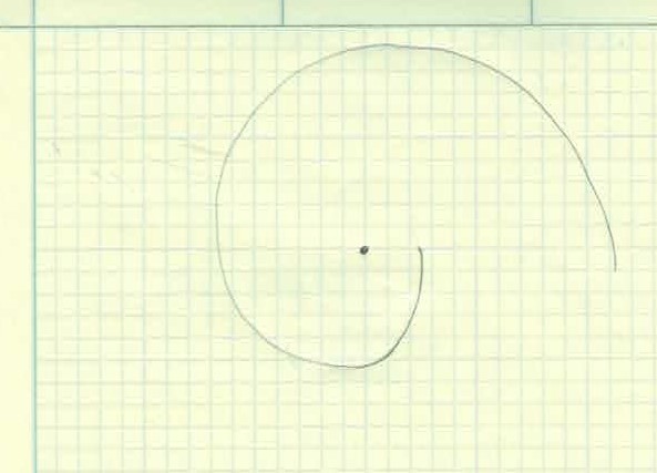
Gear teeth are designed with the unique profile and it’s called an involute profile. The involute profile is made by taking a string and wrapping it around a cylinder. We then trace the curve as it unwinds. As you can see, a curve with a constantly increasing radius is made. This is very similar to the Fibonacci curve sometimes known as the Golden Spiral.
The section of the involute curve we use is determined by how close or far away from the center cylinder and how big the cylinder is to begin with. Once again, let’s leave that to the experts and just go on their theory and know that it works.
A pressure angle is defined as the instantaneous angle the involute has where it intersects the pitch circle relative to the tooth. But that’s not important for what we want to do, so forget that. Here is what is important: Pressure angles for meshing gears must match. Standard pressure angles are 14.5° and 20°. To a lesser extent 25° is also available. The higher the pressure angle, the finer the teeth. If we’re interested in power transmission, use the 14.5° design. The 20° angled gears are more for precision because they have very little backlash. However, the you will need to hold the center to center distance much tighter.
How do I choose the diametric pitch?
Unfortunately, we do need to take a little aside to specify some terms here. I promise, it will be brief.

Lands – They are the “flattened” section of the tooth. The top land is the land at the maximum extent of the gear and the bottom land is at the minimum diameter. When meshed, there should be a small gap between the lands.
Pitch Circle – The pitch circle is the effective diameter of the gear. Ideally you will want the pitch circles of two gears to be tangent to have the correct distance between them for meshing. This information is usually given by the manufacturer and is commonly referred to as the variable “d”.
Diametrical Pitch – Diametrical pitch is represented by PD and has units of teeth/in (TPI). It is the number of teeth on the gear divided by the pitch circle (d) of the tooth. This information is supplied by the manufacturer. The diametrical pitch must be the same for gears to mesh. Since I like Legos, we will use them to do a little example. Lego block have the holes 0.314” apart so we will use that as our measurement. If I mesh two of the 8 tooth gears, we can see that the pitch diameter is one hole or 0.314. Our PD is 25.5 TPI. The 16-tooth gear uses 2 holes or 0.628” and Our PD is 16 / 0.628 or 25.5 TPI. We would also find that the 24 and 40 tooth have a 25.5 TPI if we did the math. These gears mesh together because they have the same pressure angle and diametrical pitch.
How do I calculate gear speeds and forces?
Gear Speed Ratio
With gears, the speed ratios are quite simple: you count the teeth. Assuming that the gears have the same diametrical pitch and pressure angle, they will mate. Now all we have to do is count the teeth to see what the speed ratio will be. If we use a 40 tooth and 8 tooth gear, we can divide by the smaller one and see that our ratio is 5:1. That is the smaller gear will need to rotate five times to cause the larger gear to rotate once. The gear ratio will tell us how speed and torque are related.
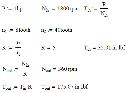
For example, we have a 1 hp electric motor rotating at 1800 rpm and the shaft is attached to the 10-tooth gear and drives a 45-tooth gear. We can calculate that the gear ratio is 4.5:1. From this, we can calculate the output speed is 400 rpm. The input torque at 1800 rpm is about 35 in-lb. We can then multiply this by our gear ratio and find out that the maximum output torque is 175 in-lb. It needs to be noted that this does not account for any inefficiencies in the system. Gear mesh inefficiencies and bearing friction will reduce the torque transmitted but have no effect on the speed.
Spur Gear Forces
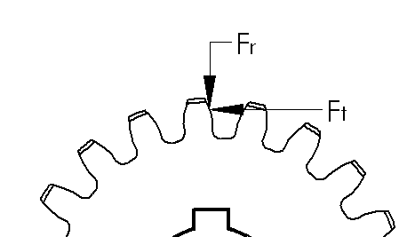
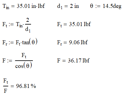
Now we are going to talk about the transmission of torque and force. The first thing we’re going to do is create a quick free body diagram on a gear tooth. Because of the involute tooth design, we can make our calculations based on contact at the pitch circle diameter. We have the tangential force, Ft which is the input force that transmits motion. Because of the gear’s pressure angle, we now have a radial force, Fr, that pushes the gears apart. As you can see, having a higher pressure angle will create higher radial forces. To maximize efficiency, ball or roller bearings are often used even when rotation speeds may be slow enough to use cylindrical or other non-moving bearings.
By solving for the statics, we can find Fr and the total force F. The total force is almost a useless number, but it does give some indication of how efficient the system is. The higher the ratio of Ft/F is, the more efficient the teeth are. Continuing our example, we find that the forces on the gears are as follows:
Helical Gear Forces
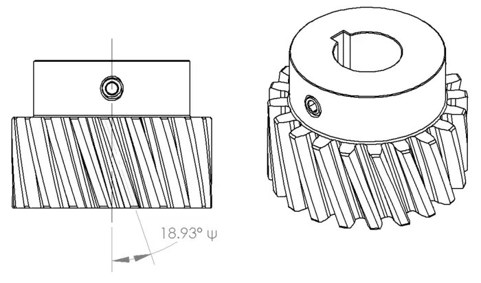
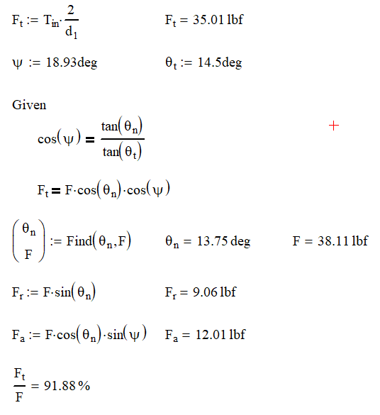
Helical gears have an added level of complexity not only in design, but also calculation. In the gear above we still have a 14.5° pressure angle, but the teeth are cut at a 18.93° angle from the shaft axis, represented by ψ. From the diagram below, we slice the gear two ways with θt equal to the gears pressure angle and θn which the pressure angle when viewed from the end of the gear. Now we can start calculating our gear forces.

Since the gear tooth is cut at an angle to the rotation axis, it should be no surprise that we are now going to have an axial component in our calculation. As a result, you will need to think of how you want to deal with this load. Having a set screw taking this load might be acceptable if you are using small torques, but you will probably need to upgrade to tapered roller bearings or thrust washers if your loads are high. Obviously, having the axial component will decrease our overall efficiency of the system as our ratio of tangential force to total force dropped from 97% to 92%. One thing to note about changing from our spur gear is that the radial force remains the same.
Tooth Forces or How a Gear is Really Sized
So, it all comes down to the force and stress exerted on the tooth. For as complicated as the gear tooth profile is and all the points that the gear can contact at is the formula is surprisingly simple. Remember those really smart guys that came up with the involute profile I was telling you about before. This is where they really earned their money.
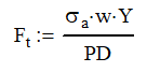
Where Ft is the tangential force, σa is the allowable stress, w is the effective width of the gear, Y is the Lewis form factor and PD is the diametric pitch. As always, watch your units. For this, you can stay in pounds and inches.
Lewis Form Factor
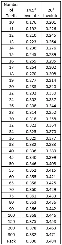
The Lewis Form Factor is the real genius of the operation. This factor takes in all the geometric variances with the involute profile and puts them in a neat little table shown here. You can see that increasing the number of teeth increases the factor as well as going to a higher pressure angle.

If you want to increase your tooth capability, you can increase your allowable stress, gear width, or use larger or higher pressure angle gears. You can also decrease the diametric pitch, because fewer teeth per inch means larger (and stronger) teeth.
Barth Speed Factor
The equation for finding the allowable stress is for static gear meshing or those running at very low speeds. Unfortunately, we probably want our gear systems to run at some speed so we need to add in a factor to account for speed.
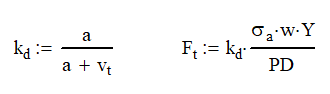
Adding the Barth Speed Factor, kd, decreases the allowable tangential force. The gear speed is the velocity of the teeth at the pitch diameter measured in ft/min. The constant a is based on the gear design and is 600 ft/min for regular gears and 1200 ft/min for precision gears.
With these equations, you should almost be able to calculate the tangential force. We are only missing what the allowable stress is. Unfortunately, I cannot give an easy answer. I can only give the lawyer answer: It depends. Here are some of the factors that will play a role in calculating the allowable stress
- Hertzian contact stress
- Gear ratio
- Material
- Surface roughness
- Lubrication
- Overload
- Dynamic Load
- Temperature
Each of these factors can be very hard to determine. I wish I could be of more help, but every case is different. My advice to you is this, go conservative! Calculate the maximum load that system can see and use a design factor or 3:1 on yield stress. Make sure that your gears are well lubricated as well. Designing to these criteria will put you on the side of caution. Remember nobody complains if your gear system lasts forever.
How do I lubricate my gears?
There are primarily three methods of gear lubrication:
- Grease
- Splash
- Forced oil circulation
Let’s examine each in brief
Grease lubrication
Grease lubrication works best with open geared systems. You basically spray on lubricant that sticks to surfaces. Since it is spray on, it has two major downfalls. First, it will have to be reapplied often. Second, since it is sticky, it is like grease and will attract dirt. As you can imagine getting some “sand in your gears” is not a good thing. Grease lubrication is meant for slow moving gear systems less than 15 ft/s tangential velocity.
Splash lubrication
Splash lubrication is where part of one or more of the gears are in an oil bath. As the gears turn, the lubricant will stick to the surface and lubricate the other gears in the system. I recommend this style of lubrication because all of the connecting gears get lubricated. Also, because the lubricant is thin, there is less power loss between gears.
Forced oil circulation lubrication
This involves oil or other lubricant to be pumped and put directly on the gears. The delivery can be poured, sprayed or even misted. This is used primarily when you have open gearing but working inside a building or even a very large gearbox. One benefit is you are also able to control the oil temperature and cleanliness.
I have used this method in the past where it was impossible to lubricate all the gears from the same pan. The application used a multitiered oil pan where lubricant was pumped to the highest pan and would spill over to the next pan when it was too high.
How do I make sure my gears aren’t too sloppy?
Sloppiness in gears is called backlash. In gear design, there is a gap between the lands; but there should also be a gap on the side opposite side of contact. If that gap is too much, there is sloppiness. If it is too little, there gears will wear prematurely because of interference.
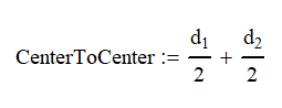
Now imagine we are looking at a crane’s rotation bearing. When we rotate the crane boom, we don’t want the bearing to repeated jerk side to side when the crane stops. Generally, if the backlash is too loose, the crane with jerk back and forth until friction finally stops rotation. That repetitive jerk on the gear teeth will cause teeth to break off from fatigue. To minimize or even eliminate this, you want to get those teeth very tight to each other. You can do this by moving one of the gears closer to the other by changing the center to center distance.
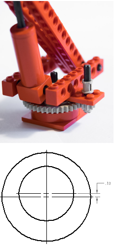
My favorite way to adjust these is to take one of them, usually the pinion, and make an eccentric ring as shown. The eccentric ring has an outer diameter that is off center from the inner diameter. Normally, 1/16” of an inch would be more than enough. The ring would sit in a bore and could be rotated as needed to adjust the shaft closer to or further apart from the other gear. Once you have it properly adjusted, you will need to lock it in place. I have a few ideas here, but I will not share them because they are proprietary. You will want to use anti-seize so that you can get these components apart someday.
Measuring Backlash

Backlash can be measured quite easily by using a magnetic mounted dial indicator. Here are the steps to set backlash:
- Find the high side of the teeth if possible. If the bearing is new there is usually a mark from the vendor. Rotate so that the pinion is acting on those teeth. (Side note: you also want the high side of the teeth to be meshed when the unit is stowed. For mobile equipment this limits the impact from road vibrations.)
- Generally speaking, the pinion gear will be much smaller, so we will want to mount the indicator on whatever moves with the pinion. In the case of a crane, it is probably the turntable
- Adjust the indicator so that point is touching a tooth on the stationary side as close to tangential as possible.
- Wiggle the moving part (i.e. turntable) by pushing and pulling on it from side to side. Watch the indicator and note the range of motion.
- Adjust the eccentric ring or other device until the range of motion is as desired. This is usually around 0.005” to 0.010” (0.12 to .25 mm).
- Lock the eccentric ring in place.
Conclusion
Gear systems are everywhere and fun to design and use. This article is designed to get the gear novice at least speaking the language of gears and hopefully equipped to design a system of their own.