

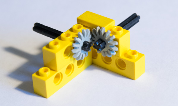
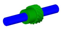
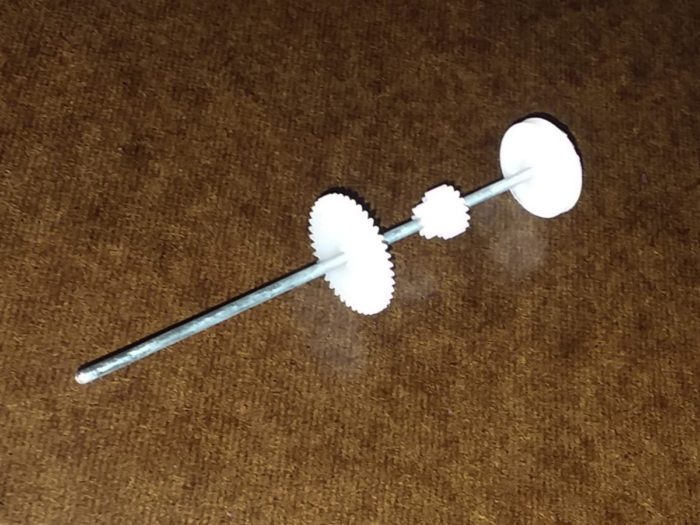
Unlike the Lego gears and shafts shown below most motors have perfectly round shafts. This makes attaching gears, pulleys and sprockets difficult.
The main methods of attaching gears to shafts are adhesives, press-fitting, cross drilled holes, compression, set screws, keyways, involute splines and taper lock bushings. Most industrial applications will use keyways and / or set screws. While adhesives and press fitting are usually done on low torque or hobby applications.
Let’s investigate each method weighing the pros and cons. I will also be using the terms; gears, pulleys, sprockets and cams, interchangeably as this article address the how the device is mounted, not what it does.
Adhesives
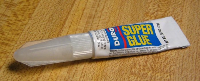
Adhesives are mostly used in hobby applications with plastic gearing. Not only because plastic gears cannot handle much torque, but also because the shaft sizes remain small in diameter.
As the shaft diameter increases the relative strength of the glue joint and the shaft strength are equal at roughly 3/16″ (5 mm) when using a conservative glue strength of 1000 psi (7 N/mm) and a shaft of C1018 steel (54 ksi, 370 MPa).
Conclusion: using adhesives is a good choice for small shafts
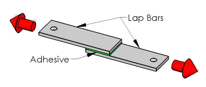
As mentioned, most adhesive manufacturers will advertise a lap shear strength of at least 1000 psi and some as high as 3000+ psi. A lap shear test is done by having two long skinny bars attached together with the glue over a measurable area. The ends of the bars are pulled apart until failure. The force is divided by the area and the result is the lap shear strength.
I usually design around the low number of advertised shear strength here as there are many factors at play which can lower the actual strength. Among these are surface preparation, surface area application, temperature and humidity.
Before applying the adhesive, you will need to rough up the surfaces of the pulley and the shaft with some sand paper (~200 – 300 grit) or a fine file. This will give the glue small nicks to grab on to. You will then want to clean and degrease with a cleanser and then dry fully. I like to use brake cleaner usually because I have it around.
To figure out if your application will withstand the applied torque. Use the following formulas.
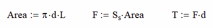
Where Area is the surface area between the shaft and the pulley, d is the shaft diameter, L is the overlap length for the shaft and pulley, F is the internal shear force between the shaft and pulley, Ss is the shear strength of the adhesive, and T is the applied (or maximum torque).
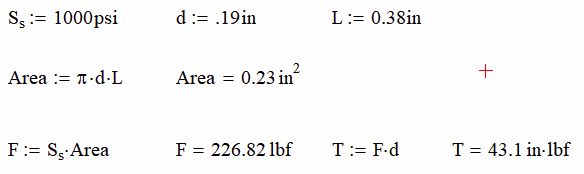
Using an average adhesive shear strength of 1000 psi, a diameter of 0.19 in, and overlap length of 0.38 in, we can find that our maximum Torque is 43.1 in lb.
There are three main cons of using the adhesive method to join a pulley to a shaft
- The torque is limited by the diameter and adhesive strength as already mentioned
- There is the ability to have the shaft and pulley out of center and / or perpendicular. This can be minimized by the tolerance between the two, but not so tight that you would wipe off all the glue.
- There is no way to adjust or replace the components without the possibility of damaging 1 or both components. Having adjustment is important and this method doesn’t allow for it at all.
Joining Shafts Together? Check out our guide to shaft couplers.
Press-Fitting
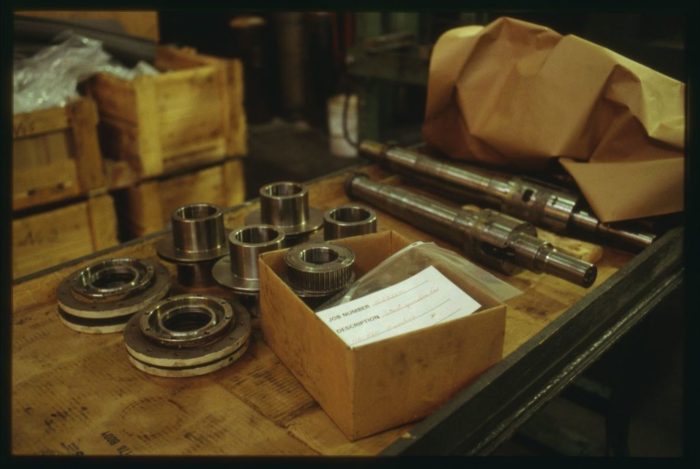
Press-fitting is a tried and true method of attaching gears to shafts. It has been in use in the railroad industry as a method to save money when wheel assemblies wear out or become out of round.
The main wheel weldment has a precisely machined diameter and then a thin band of hardened steel is applied around it. The band or “tire” is actually smaller than the machined surface. This allows the inexpensive band to be replaced from time to time instead of the whole wheel assembly.
The following video shows how the tire is removed from the wheel by using heat. The band will expand in diameter as the temperature rises. The wheel (inner diameter) will stay roughly the same size because it has a lot more mass and will radiate heat away faster.
At this point, the band can be pried off and a new one installed by the same method.
Because there is no mechanical lock on this, it is 100% based on friction and it can slip. Measuring and determining the press fit is difficult and assumptions usually need to be made.
Super Slow Free Online Shaft Press Fit Calculator or Go Pro
Where Pr is the pressure between the surfaces, δ is the amount of press fit, d is the shaft diameter, do is the outer diameter of the hub or gear, di is the inner diameter of the shaft (if hollow), μ is the coefficient of friction between the materials and E and ν are the Young’s Modulus and Poisson’s Ratio of the materials.
Heating up the material will increase the diameter; therefore, decreasing the amount of press fit, δ. This make the gear easier to get on or off, but the end result the same once it cools.
If doing this at home with plastic gears. Try heating them up in the oven at about 175° to 200° (79°C to 93°C) and then sliding them on the shaft.
This method is adjustable, but not easily and you may need to disassemble multiple components so that heat does not destroy them.
Cross Drilled Holes
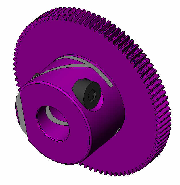
Drilling a hole through both the gear hub and the shaft is a great way to get a lot of torque. It also prevents the shaft from being overloaded because the pin will shear (break) if the torque is too much. There are three main types of pins to use in this application listed below from weakest to strongest.

- Roll (spring or slotted) Pins – These are flat bars that have been rolled to a round shape. They tend to spring open (hence spring pins) allowing enough of a press fit so that the pin won’t slip out. I recommend these over the other two options.
- Shear Pins – These pins are solid and have a notch at the midpoint where the pin is designed to fail at a specific force. It is important to get a pin where the notch will be at the same plane as the shaft diameter.
- Dowel Pins – These are just high strength solid pins. If your hole is too big, you will probably have to glue these in place (shear pins too). If your application reverses direction or load, you can encourage the glue to fail prematurely and the pin to fall out.
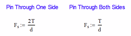
Each of the pins will have an advertised breaking strength and you can select the diameter and type based on the equations below. Fs is the shear force, T is the applied torque and d is the shaft diameter.
This method gives you lots of capacity to handle more torque, but is still doesn’t give any adjustment once the hole is drilled. If you mess up too many times, the shaft will look like Swiss Cheese.
On major benefit is that nearly anyone can make this joint. All you need is a drill, drill bits and a hammer. I recommend drilling a smaller diameter 1/16 – 3/32 first and check your alignment with a toothpick. If it is good, drill it out to the diameter you want. If not, rotate to another part of the shaft and try again.
Compression Hubs
While not a common method of attaching gears to shafts, it is available. Once the gear is slid over the shaft, the set screw is tightened and friction will carry the torque. The coefficient can be reduced inadvertently due to oily shafts or the use of anti-seize. It is best to use dissimilar metals when using this method.
The cost of making the reliefs in the components makes this type method cost prohibitive in most cases.
Just avoid this type of joint!
Set Screws
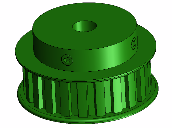
The set screw (only) method of attaching to a shaft is very common with timing pulleys, gears and sprockets.
It is difficult to determine what kind of torque you can get out of a coupling like this. The result can vary wildly because of friction coefficient, applied torque, lubrication of the threads and set screw type. The basic equation is as follows:
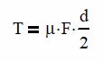
Where T is the output torque, μ is the coefficient of friction, F is the normal force from one setscrew and d is the daft diameter.
Most people just tighten the set screw as much as possible. As long as the pulley doesn’t slip from excessive torque, everything will be all right. However when it does, you will quickly wear a groove into the shaft. This makes your shaft diameter smaller; thus reducing the maximum torque you can achieve.
The main benefit is that this method is 100% adjustable for rotation to the shaft and along its length. Generally, this method is only available with shaft sizes 1/2″ (13mm) or less.
Keyways
For most industrial applications the standard is keyed shafts. By far any off the shelf gear will be available in a variety of bores sized with keys slots. You can also buy them with unfinished bores and cut your own keyway if you like.

When selecting a bore size, make sure that you aren’t selecting a shaft that is too big for the for the gear. Recently, I had a system that used a 10-tooth sprocket on a 1” shaft. The system had some pressure spikes in it at startup and actually cracked the sprocket in half.
It was able to do this so easily because the material between the outside of the hub and the keyway was only 1/8” thick. We were able to double that to ¼ by adding one tooth. This is a situation where an involute spline would be a better choice (more on that later).
Most gears are held from sliding on the shaft with just one or two set screws. Generally, one screw will be on the key and the other will be 90° to it and press against the shaft. For spur gears, this is adequate, but for helical gears, there needs to be more of a positive engagement on the shaft to account for the side load. Possible solutions are thrust bearings, tapered roller bearings or snap rings.
When in doubt, go with a keyed shaft.
Involute Splines
Involute splines are structurally better than keyways for transmitting high torques. Instead of one large key, we have many smaller keyways that evenly distribute the stress around the outside of the shaft better.
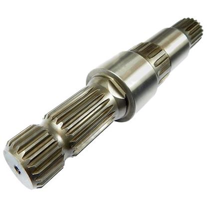
This can be a good and bad thing. It is good because the shaft won’t break as easily, but bad in the way that there is no mechanism that can safely fail if too much torque is transmitted.
An involute is the curve that is made when a string is wrapped around a cylinder and then the end of the string is traced as it is unwound. This is profile of the sides of each tooth on the spline.
The pros of this connection method is that large torques can be transmitted with ease and it is adjustable along the length of the shaft and can be oriented at many angles to the shaft. There are several cons including:
- A set screw may still be needed
- There is no fail-safe mechanism like a key to prevent too much torque from being transmitted
- It is super expensive
Best Guide to Understanding SAE Shafts and Mounting Flanges
Taper lock bushings
Taper lock bushings aren’t a new method of attaching to a shaft; they still use a key. But they are a different way to mount the sprocket to the shaft. Instead of 2 main parts, we now have 3. The sprocket, the shaft and the bushing.
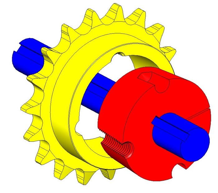
In the figure above, the red bushing will slide onto the shaft in the desired position. The sprocket will then be slid over the bushing until snug. Set screws will be inserted at the top and bottom locations. As the set screws are tightened, the taper will force the bearing gap (on right) shut and lock on the shaft.
There are three main benefits of this design:
- Low profile
- The bushing can be removed by inserting the set screw into the hole on the left and screwing it in.
- No anti-seize is required! This is the one application where the bushing can be removed without the use of anti-seize. This makes it perfect for environments where anti-seize may be detrimental. The food industry comes to mind here.
Conclusion
There are many different methods of attaching gears, sprockets, cams and pulleys to shafts. Some, like adhesives and press fitting, are designed more for hobby applications. Others are clearly meant to survive out in the real world, like keyed shafts, taper bushings and involute splines.