

It is not uncommon that we will need to couple pumps, motors and/or engines together. Jaw-style couplers help with joining shafts together. With the use of these couplers, we can adapt and fit many different types of shafts together, but interestingly, there are so few choices! Granted, there are lots of choices in the catalogue, but it seems that there should be many more shaft sizes, spline cuts and keys to choose from. Why aren’t there more? Also, what about the outside of the parts? They look like they were designed to be mated with something.
Your questions are not unfounded. There was a standardization that took place years ago. SAE led the way with standardized shafts and mounting flanges in SAE J744. The standard takes a seemingly infinite number of combinations and boils it down to a manageable number of combinations. The fewer the choices, the easier it is on engineers. Plus, manufacturers can often bring a product to market quicker since there aren’t many custom options.
Mounting Flanges
The Society of Automotive Engineers (SAE) has standardized the mounting flanges for hydraulic pumps and motors using a letter codes and the number of bolts used. The sizes are already designed to be able to properly carry the load with medium strength fastener (Grade 5 or equivalent)
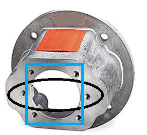
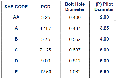
SAE J744 specifies the flanges by a letter and a bolt count. In a two bolt pattern, the two bolts and center pilot are all in line. Two bolt flanges (black) come in AA, A, B, C, D and E configurations. Each one gets successively larger. The four-bolt ones have the center pilot surrounded by four bolts arranged in a square around it. These four-bolt (blue) configurations are available in B, C, D and E configurations. These flanges are constructed so that the center pilot will take the main x-y loads and the bolts only take the torque load. Below, is a table for the two bolt configurations. It contains the pitch circle diameter, PCD, which is the diameter of a circle drawn centered at the pilot and intersects the center of the bolt holes. It also has the size of the bolt holes and the pilot diameter.
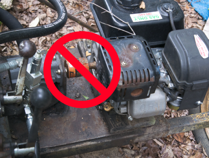
Keeping your pump and motors on the same center and parallel is critical and often difficult to do. It can mean the difference between a long-lasting system and one that constantly needs maintenance. The example here, a log splitter, is almost exactly how not to do this. Let’s take a look at several problems:
- The pump (left) is mounted on a thin piece of flat steel and cannot be adjusted for angularity.
- The motor is mounted on a piece of wood. As temperature and humidity change, so will the height and angle of the engine.
- The aligning of the shafts is entirely done by positioning the engine. There is limited flexibility. Washers were used to shim and they have discrete shimming heights which limits adjustment.
- Even if we get all of these things perfectly aligned, which didn’t happen, if the jib is loaded to this side, the stiffness of the frame causes these to shift. Each loading of the jib changes the alignment if only for a few seconds.
This is not ideal and will definitely wear out the spider coupler faster. However, there are three options to get great alignment with a pump or motor.
- Design and machine something yourself
- Buy a pre-machined coupler
- Close Coupling
Design it yourself
If you go the route of designing something yourself, make note that it must be machined after any type of welding. I’ve tried to create weldments that use fixtures and heat-controlled welding processes to make pre-machined parts align. It just doesn’t work. Many times, it takes a large weld just to carry the required torque load so heat can only be minimized to a certain point. I’ve also had parts warp in the heat of a powder coat oven. No, if you want to design an interface yourself, it needs to be post-machined or machined after welding. Designing something yourself is a good idea for large run quantities and custom interfaces. If this is a ‘one off,’ a much better choice is to:
Buy a pre-machined coupler
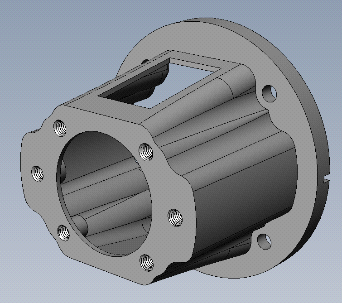
Many times you can buy a pre-machined cast aluminum coupler if you are coupling an electric motor or gas engine to a hydraulic pump. Grainger, McMaster Carr and many others have these products online. They are wonderful because they ensure that the shafts will lineup perfectly and have an added safety feature. They usually shield all the way around except for a small opening so that you can tighten set screws in the jaw coupler. Some even have options for a plastic or rubber plug to fill this hole. I always opt for this option. Be sure to mount with the opening on top so that the plug does not fill with water and debris or the vibrations cause it to fall out.
Shaft Standardization
SAE has standardized shaft configurations to use keyways and splines to attach components. This limits the number of choices for each shaft size to one key and one spline. This makes it easy for the customer to specify mating components and the manufacturer to minimize component configurations.
You may have noticed that I skipped over close coupled arrangements. I did that because I wanted to discuss SAE shafts first. We will address that later in this section.
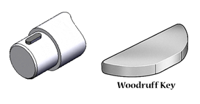
Shafts come in two varieties: Keyed and splined. We are probably all familiar with keyed shafts because this type is predominant in the industry. A keyed shaft has a small recess where a key is placed in. This assembly is then inserted into a hub. The main purpose of a key is to transmit torque, but prevent larger component failure when things go wrong. Keys are made of high strength steel, so if the key does break, diligently inspect all aspects of the system before replacing. Also, if your key breaks, be sure to inspect the shaft and hub for damage. Rolled edges from a broken key simply will not work correctly and must be replaced.
Keyways are designed in proportion to the shaft diameter. The intent here is to offer the maximum strength on the shaft while balancing the shear stress on the key. To put it another way, if we enlarge the key, the shaft will be inadequately designed. If the key is smaller, it won’t be able to transmit the rated torque. If you are designing a shaft or hub for a key, be sure to consult your Machinery’s Handbook for tolerancing guidelines.
The keys can be rounded (shown on shaft), square or a ‘woodruff’ cut (shown). As with anything, you can actually have many sizes and variations of each one including; oversized, undersized, stepped, and high profile. A stepped key will adapt between a shaft and hub of different sizes.
These shafts come in letter sizes A, B, C, D and E with double letters AA, AH, BB and CC. Each one specifies the shaft diameter, shaft length and total length. The key width is also specified and the depth is ½ of the width.
Splined Shafts
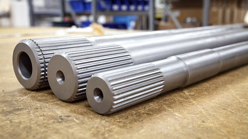
A splined shaft is much different. The full description is SAE 30° involute spline shaft, but in practice if you say splined shaft everyone will know what you are talking about. In appearance, they look like gears and essentially that is what they are. As you can guess, they do not have any mechanism to deal with over torque like a keyed shaft does. So these also have the same SAE letter codes available as a keyed shaft. A sizing table will have the spline details, nominal diameter and total length. Spline detail are displayed as 11T 16/32 DP. This is similar to how a gear is specified. In this example, the spline has 11 teeth and 16 teeth per inch of diameter (DP, diametric pitch). I’ll be honest; I do not know why the 32 is there. It seems redundant to me. The bottom line is this; if the teeth and diametric pitch match, the shaft and hub will fit together.
Close Coupling
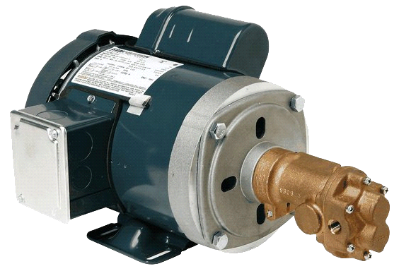
Yes, finally to the close coupling. This is when we fit our pump or motor to have either a splined or keyed hub instead of a shaft. This allows us to eliminate the entire issue of shaft alignment and jaw couplers by inserting the electric motor shaft inside the pump. In the image here, you can see that the pump is directly connected to the motor and there is no housing or coupler. This is a great option if you are driving multiple pumps from the same power source. In this case, you can have the pump that attaches to the motor with a hub on one side and a shaft on the other. You can then attach your second pump. Granted, having a hub instead of a shaft is more expensive on the front end, but it may end up paying for itself quickly if you can eliminate jaw couplers, machined framework and the time it takes to assemble.
In figuring out the specifications of our parts, SAE has helped by laying out the information for us. A very quick web search will provide you with the tables of all the shaft and mounting information. All that needs to be done is to answer these questions:
- What kind of shafts are available components that fit my needs?
- Which mounting bracket options are compatible?
- Can I close couple this?
One last word of advice when working with couplers and shafts: Remember to always use anti-seize between the two faces in order to prevent any rust or corrosion. It is more than likely that you will need to remove or separate these parts at some point. If these components rust together, you might as well throw them away. You can try to pry them apart or use heat, but it is more than likely you will damage the internal components of your pump and motor in the process. Please, use the anti-seize. It is inexpensive and available in any auto parts store.
In Conclusion
There has definitely been a lot of information discussed here. After reading this, you should be able to:
- Know good and bad ways to couple a pump and motor
- Understand that shafts and flanges are standardized
- Find and interpret the SAE tables and to ensure your pump and motor will match up
- Understand the benefits of close coupling
If you can understand these basic things, this will put you ahead of your peers in designing hydraulic systems.