

There are many times in my design career that I needed to translate an object without rotating. Lifting an object on a table is a great example of this. At an airport we may see a baggage loader using a scissor lift to load and unload your personal items.
Hydraulic leveling uses two identical cylinders to maintain level. One cylinder tracks the motion of the apparatus and the other recreated the motion on the other end of the apparatus. This is done by connecting the cylinder bores and rods, respectively, to each other.
There are five main ways to move items without rotation. They are:
- Parallel Links
- Chain and Sprocket Leveling
- Scissor Lifts
- Hydraulic Leveling
- Electronic Leveling
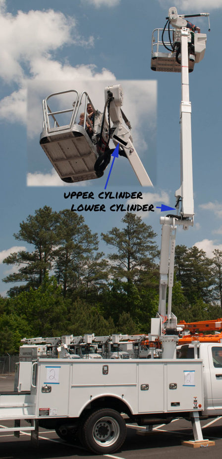
This article will focus on hydraulic leveling which is the most complicated mechanical method of keeping a surface level because there are many components that need to be factored in. One reason that hydraulic leveling is superior, it that it allows the two ends to move relative to each other as in the image below where the boom in the aerial work platform shown below can extend. Parallel links and chain and sprocket are deficient because they cannot change length.
The traditional use is for platform leveling on a man lift. At the platform, there would be an upper hydraulic cylinder between the platform and the boom. This cylinder is driven by a similar lower cylinder between the boom and the riser or knuckle. It is important to note that the lower cylinder does not raise and lower the boom, it is there to tell the upper cylinder what to do.
How It Works
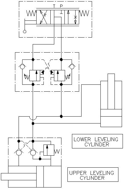
Looking at the schematic below, we can see that there are five main components: The upper and lower cylinder, a load holding valve mounted on the upper cylinder, a dual counterbalance valve (center) and a directional control valve (top). The directional control valve and dual counterbalance valve are for re-timing, so we will ignore them until later in the article.
We will illustrate how the system works by going through a cycle:
We will start by having a boom in the lowered position so that the lower cylinder is retracted and the upper cylinder is extended. When the boom is raised, it will force the lower cylinder to extend. Oil in the rod section will be forced to leave and travel into the upper cylinder where it will build up pressure and pilot open the counterbalance valve and enter in the rod section there. Oil from the bore section of the upper cylinder will be forced out and travel to the lower section.
When we lower the boom, the opposite happens.
To design good hydraulic leveling, you will want to consider six factors:
- Cylinder Size
- Extra Stroke
- Load Holding
- Limit Pressure and Fluid Velocity
- Account for Deflection
- Adjustment
Cylinder Size
The first thing that you will want to do when designing hydraulic leveling is select cylinders with the same geometry. The bore and rod size and the stroke length must be equal. If there is any difference, you are not going to get good results.
Extra Stroke
It is recommended that you allow for at least ¼” of extra stroke on each end lower cylinder. You don’t want to get into a situation where the boom lift cylinder is not quite all the way extended, but the lower cylinder is extended already. As you can imagine, the boom lift cylinder is much more powerful and it is going to pull the lower cylinder apart. Very bad things will happen. You also want extra stroke so that variations in fabrication don’t stack up and cause problems.
Load Holding
Hoses occasionally break, so you also want to add on load holding right on the upper cylinder to prevent any unintended motion of the platform. Counterbalance valves with 3:1 or 4.5:1 ratio should do well in this application. Be sure to set them at least 15% higher than the system pressure.
Limit Pressure and Fluid Velocity

In order to keep these cylinders timed we need to limit the pressure and fluid velocity. We do this so there is not a lot of energy loss when we articulate the boom.
First off, you are going to want to look at the velocity of oil that’s exiting the cylinders and keep it to a velocity of less than 10 feet per second. This would be the same as you would have for a standard hydraulic return line.
The reason for this is that you don’t want to have large pressure drops just to move the fluid back and forth between the cylinders. You want the fluid to do the work of maintaining level and not just trying to get out of a counterbalance fast enough. Increase your hose size to remedy this.
Second, keeping your working pressures low is important. You will want to be working with pressures about 2/3 of the system pressure. For a 3000 psi system, we will want to have our cylinder operate at 2000 psi. The reason for this is we don’t want sudden pressure spikes causing the counterbalance valves to open and level to change unintentionally. As a result, you will need to increase the cylinder bore and stroke length on both cylinders.
Two great resources to aide in your design.
Account for Deflection
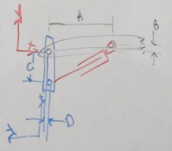
This is probably the most overlooked criteria because it is not obvious. In an ideal world, designing the cylinder geometry exactly the same on both ends will work perfectly. Making geometry the same would require that the dimensions (A, B, C, and D) in the picture here are the same for both the upper and lower cylinders.
Keep in mind that the rotation of these components can be changed. Most common in the real world is that booms will deflect. When the boom is loaded in a horizontal position it may deflect 5° but when it is near vertical, it may only deflect 0.5°. If we don’t account for that, the platform will not track correctly and be out of level.
To account for this, the cylinder geometry must cause the platform to rotate 4.5° more than the boom rotates. This causes the cylinder geometry to be slightly different on each end.
If this is the case in your design, you will want to have the geometry slightly different, but keep the same bore, rod and stroke length in the cylinders.
Manual adjustment
Hydraulic leveling isn’t perfect and from time to time, you will need to adjust the platform level. In the schematic below, we will need to add a directional control valve for two reasons. The first is obvious; to occasionally adjust the platform level. Second, we need a way to prime the cylinders and hoses. Air is not a friend in any hydraulic system, so getting oil in and air out is important. Closed systems like this one are difficult to get the air out so I recommend cycling the platform fully when the boom is up and down at least twice.
Direct use of a direction control valve with closed center work ports presents two problems. First, if there is a pressure spike, flow back to the tank is blocked so the system will need to absorb the excess pressure. The second reason is that while the schematic shows the ports being blocked, in reality the valve does have small amounts of leakage. This is due to the valve spool having a small amount of clearance with the hole that was bored in the valve. While this amount of fluid is small, it is usually measured in drops per minute. Leaving a unit setup overnight might yield a dramatic change in platform angle.
Placing a dual counterbalance valve in between the directional control valve and cylinder circuit solves both of these problems. It will make a no-leak seal on the cylinders but also allows for relief from pressure spikes as well as thermal induced pressures. These counterbalance valves are purely for load holding so using a higher ratio valve is appropriate. I recommend a 10:1 valve set at 15% higher than the system pressure.
Hydraulic Leveling – Type 2
There is another type of hydraulic leveling where a level switch activates a directional control valve. The level switch can detect when the platform is more than a few degrees out of level and the directional control valve will respond accordingly. This type of leveling is simple, but very jerky and has a ratcheting effect. I mention it only to round out the picture because this type of control has been replaced with modern electronic controls.
Conclusion
Lifting objects is an essential part of engineering. Keeping them level throughout the lift is a welcomed challenge but can be stressful. After reading this article you should be able to take initial steps to designing a hydraulic leveling system.