Recent Posts

How to Model Weldments for Efficient Finite Element Analysis

As engineers, we want accurate model for finite element analysis, but with more accuracy comes longer run time and difficulties meshing.  The method shown below is a way to gain maintain accuracy while reducing run time.

To get an accurate Finite Element Analysis results for a weldment with shorter run time follow these steps:

  1. Model each weldment as one part
  2. Add in welds as chamfers
  3. Make cuts where needed
  4. Apply mesh controls on welds

Mesh Singularity – Before we get too deep into the weeds here, I want to point out the mesh singularity may or may not be an issue here depending on the model’s particular geometry.  Since there are a sharp corners in the model there is the possibility of mesh singularity and divergence in results.  Divergence is when the mesh is refined more and more, but the stress at a particular physical location usually increases dramatically as the mesh is finer.  This makes interpreting the actual stress very hard.  Mesh Singularity and Divergence require a whole article of their own and are out of the scope of this one.

Welds – The main part of what makes a weldment is welds.  Naturally, the stress will flow different through a weld than if we just had the parent materials present.  Therefore, we need to model the welds and their proper sizes to get trustworthy results.  In a previous role, a colleague did not model welds and modeled a doubler plate as part of the primary structure.  A plate was attached to the doubler and a load was applied that pulled the doubler away from the primary structure.  Since no care was given to the weld or doubler, the section was modeled twice as thick and FEA showed no high stresses.  The welds cracked quickly in an endurance test.  The point of the story is that welds matter in our FEA models so we should spend the extra time here to get the model right.

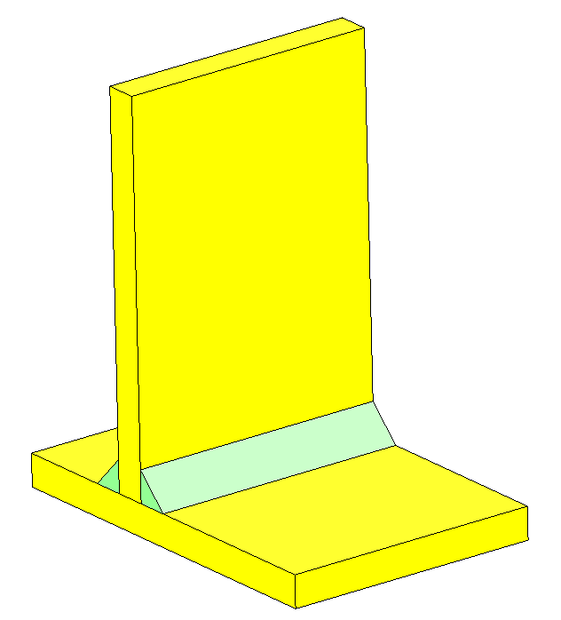
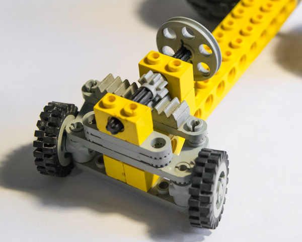
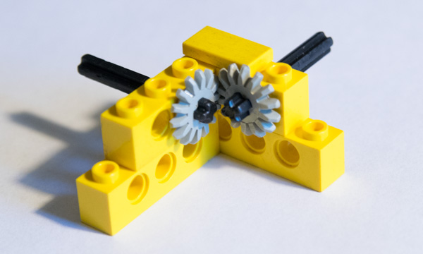
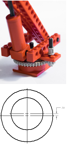
Most welds factor into 2 categories; bevel and fillet.  (By the way, I have no idea why a fillet weld looks like a chamfer; should we not call them chamfer welds?)  Fortunately, a bevel weld does not need any additional modeling done.  The fillet weld is more difficult because it requires additional material and then special consideration for how the parent materials behave. Looking at the figure here, the yellow plates are joined by two fillet welds.  These welds need to be modeled and then the contact between the two yellow plates needs to be addressed.  One method is to use a no penetration contact and the other is to use a distance mate to separate them slightly.  Both of these are ideas that don’t move us toward our goal, so we won’t pursue them further.  Let’s get on to the plan.

Model Each Weldment as One Part

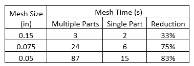
This is where the time savings comes from.  The main benefit of modeling a weldment as a part comes with the meshing headaches you will avoid.  When meshing lots of parts in Solidworks Simulation, the parts that touch need to have all the same mating nodes.  This can be very difficult for the software to do.  One trick for this is Solidworks sorts the parts alphabetically and meshes in that order.  You can reorganize the meshing order by renaming parts A_, B_, etc. so that the most complex parts are meshed first and get to set mesh parameters for the simpler components.  This has saved me many headaches over the years.

The other way that modeling a weldment as one part helps to reduce FEA run time is it allows you to remove any contact sets from the analysis.  This removes a lot of run time from the solver process.  In the figure above, most designers would add a no-penetration contact between the yellow plates, but this adds so much time to the analysis.  See the data in the tables below for run times by model type.

We can see here that the main benefits with switching to a one-piece weldment is reduced run time by removing contacts and less headaches from meshing failures.

Now I know that you are all thinking, “It is going to take more time to model this.”  And you would be right; well, kind of right.  You see with the two benefits mentioned above the time savings in FEA are well worth the time setting up the model.  However, I would challenge you to go one step further and model it as one piece as you are designing it.  This will save even more time!  If you model as one piece from the start, all you need to do is make a few tweaks for FEA.  You can also send it to a drafter and he or she can break down the model into piece parts.  This has proven effective because the drafter will not only have a great template to go by, but he or she will know where all the welds go and what size they need to be.  This one step can be a tremendous time saver for the whole design process!

Add in Welds as Chamfers

So one of the awesome benefits of modeling a one-piece weldment is that you can easily add welds to the model via the chamfer option.  This allows Solidworks to process very complicated geometry with very little effort.  I usually choose a weld with equal legs rather than one with a leg length and an angle.  I do this so that even if the welded components don’t meet at right angles, the weld will be modeled correctly.  I also label the chamfer with the size so that I can easily see what size welds I need (i.e. 25-chamfer).  This way I can add or remove welds from different features as they change sizes.

Make cuts where needed

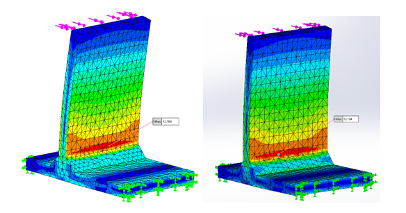
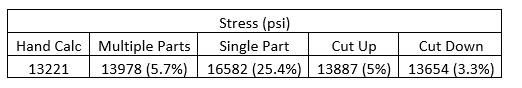
In the figures below, we can see that the stress flow is different when we go from the no penetration multi-part model to the single part.   Our run time has been reduced dramatically, but our accuracy has gone down a lot.  The model is loaded with lateral 100 lb. load and the two ends are fixed.  When calculated by hand, the stress should be 13,221 psi in the high stressed area.  The left figure is the multi-part model where the stress moves around the no penetration contact.  The right figure shows the stress flowing through the center where the two plates intersect.  Obviously, this is not a proper stress flow path.

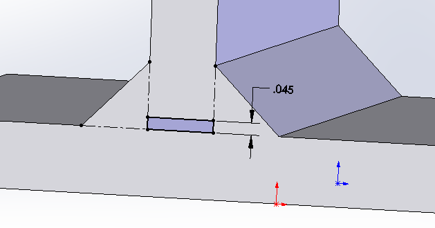
To remedy this problem, we need to make a cut in between the two plates.  There are three ways to do this: make the cut go up, down or split the difference.  The choice you make will depend on your situation.  Going up might be more accurate in one case, but less accurate in another.  One thing to mention is that the location of the cut will affect the results, but it will have very little impact on the run time.  The cut below is shown going up with a gap of 0.45” and is as wide as the vertical plate.  The 0.045” gap is a gap that Solidworks seems to like when meshing.  There are situations where you may need to go up to 0.0625” if meshing fails.

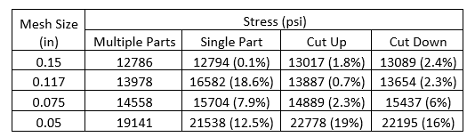
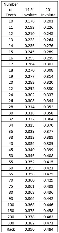
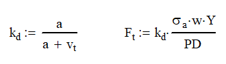
The table here shows the results for the multi-part, single part with welds and then adding the cut up or down.  As you can see, the results are very accurate for the coarser mesh of 0.15” but get worse as the mesh is refined.  This is the problem of singularity I warned against earlier.  To minimize the error, I recommend getting three elements (4 nodes) on the face of a weld.  For a right-angle fillet weld, this is as simple as mesh size = weld leg / 2.13.  In our case the ¼” weld gives a mesh size of 0.117”.  This is a good rule of thumb and it is not always exact.  You will need to inspect the critical welds for three elements along the face.  Going less than that is just too coarse of a mesh and small gives untrustworthy results.  For example, the figure below (single part with the cut going up) has 6 nodes on the face of the weld.

A word on accuracy – As engineers, we need to make assumptions and judgement calls all the time.  This is one of those times.  In my first FEA class, the instructor opened up with the statement, “All FEA is wrong.”  He is right.  You may have noticed that I went and did a simple hand calculation to get a reference for what the magnitude should be of the stress.  I highly recommend that when you see FEA results you don’t like, do a hand calculation to see if your design is sufficient.  Many times, simple calculations like this can save you a tremendous amount of time and frustration.

In this problem, I used my formula to get a mesh size for the weld which was 0.117”.  The results from the multi-part run were 5.7% higher than the calculated stress.  The cutting down model gave us the best results of 13,654 psi which is off by 3.3%.  To be honest, I am generally happy with FEA results that are 5% to 7% off of the calculated (or measured) valve.  I get that good, warm fuzzy feeling when the FEA results are also higher than the calculated value, this means that when I design for the stresses in FEA, the design should have inherently lower stresses.  If your hand calculation stress ends up being higher than the FEA results, check your mesh at the weld.  You can adjust this as necessary to get better results.

A doubler example – The fillet weld example is the primary complication experienced when changing from a multipart weldment to a single part weldment.  The other complexity is the doubler plate.  This one is a little simpler in the approach.  Simply model in your doubler with an extra 1/16 inch in height and add the welds that secure it in place.  You will then make a cut on the inside of the doubler that is 1/16” think in the shape of the doubler.  This will give you the proper weld size and plate thickness.

If you doubler is designed to take loads normal to its surface, you may run into issues.  If the load is compressive in nature and pushes the doubler into the primary structure, this cannot be modeled without the aid of multiple part weldments and no-penetration contacts.  While this may be a tendency for some engineers, I would recommend against it.  There is no guarantee that the plates used will be perfectly in contact with each other after welding, or even before welding.  This would then require the doubler to deflect some amount before coming into contact with the primary structure.  You are a better engineer than I am if you can predict this. 

Instead, I recommend that you assume that the doubler takes all the load.  If the doubler absolutely needs to utilize the primary structure, add plug welds near the load application point will make a huge improvement. 

In our example we have a 2.5” OD tube welded to a doubler and that is welded to the primary material which is a round disc with the edge fixed.  (In practice, this is poor practice because it puts the root of the weld in tension.  Since you can’t inspect the root of the weld, we can’t see any cracks until they have propagated all the way through the weld.  Some plug welds could remedy this issue.)  As you would expect, the tensile loading on the tube pulls the doubler away from the primary material.

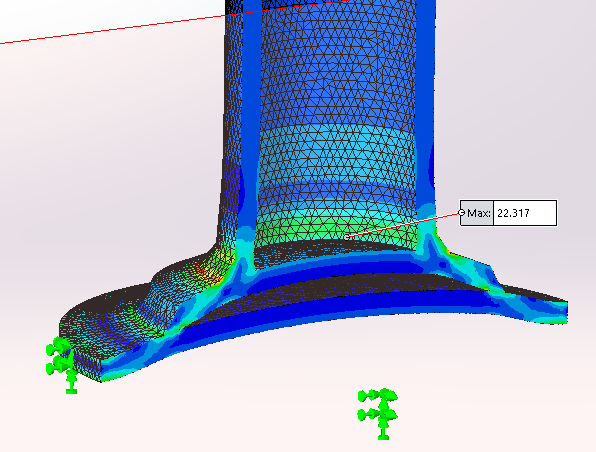
If we model this as a single part with no gaps, the two plates will act as one causing the stresses to be greatly reduced.  This is what got my colleague in trouble.

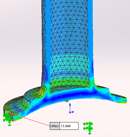
To remedy this, I added a 0.45” cut upward into the tube.  I also thickened the doubler plate and added a cut that is 0.625” up into the plate.  You can adjust the cut going into or out of the tube, but the cut should always go into the backside of the doubler plate.

Apply mesh controls on welds

To further reduce your run time, you can specify different mesh sizes in different areas.  In this example, a global mesh of 0.10” took 17 seconds to run.  If we change our global mesh to 0.25” and apply a mesh control to the weld surface of 0.10, our run time is reduced to 4 seconds without any degradation to the area of concern.

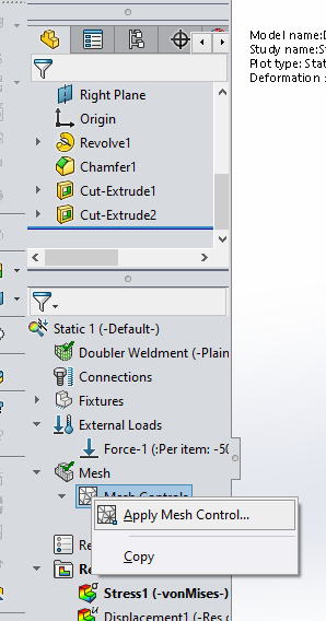
You can apply mesh controls by right clicking under Mesh and selecting Apply Mesh Control.  Then select the faces that you want.  I’ve selected the two faces of the welds and the small cutouts inside the part as well as the bottom of the tube.  If you don’t like how quickly the mesh transitions from the smaller to larger size, you can decrease the a/b ratio.  A value of 1.5 is the default, meaning that each element size can only be 1.5 times larger than the one next to it.  This can be reduced so that the transition takes longer.

Check your model and look for deflection

As FEA engineers, we need to be thorough in our modeling and give it a check before performing FEA.  The best method I’ve used it to look at sections of the model looking for the areas that need to be cut behind the weld.

Once you have your first run of FEA, be sure to check the deformation.  Make sure that it is deforming according to what you would expect.  Many times, this can be done by visual inspection.

The next step is to take sections of the model and inspect for high stresses on the internal surfaces of the model.  The doubler example above is a great illustration of this.

Conclusion

Following this simple 4 step process can greatly reduce the run time and headaches of doing FEA on large weldments.  This process also allows you to run larger models with multiple weldments without absorbing extra processing time.  Just remember to:

  • Model
    each weldment as one part
  • Add
    in welds as chamfers
  • Make
    cuts where needed
  • Apply
    mesh controls on welds

When applying your mesh control strive to have 3 elements (4 nodes) across the face of the weld for accurate, trustworthy results. 

An Easy Guide to Selecting Spring Materials

Selecting a spring material can be challenging and confusing.  I have often misdirected by the depth of great insight to this subject.  Sometimes too much information leads to indecision.

Music Wire Steel is the best choice in spring material.  Only change to a different material if your spring is over 0.18″ in diameter, used in a highly corrosive environment or used medical, food, aeronautics or nuclear applications. There may also be better materials for used in extremely high or low temperatures.

First of all, this is a very broad topic and is not an in-depth resource by design.  If your questions are not answered here, please reach out to spring manufacturers for your particular design needs.  Whatever situation you are in, they have probably seen it before.

Creep and Magnetism

Before we get into the specifics of spring materials, I wanted to elaborate on two terms first.  Creep and Magnetism.

Creep is a form of plastic deformation but it occurs under lower than yield loads and over long periods of time.  Aluminum is notorious for this.  The power distribution industry has longed to use more and more aluminum instead of copper due to price, availability and better electrical properties, but creep has prevented them.  What happens is that when an aluminum wire is terminated with a screw clamp, the aluminum, over time, will conform to the shape of the screw clamp.  This leads to a loose wire and the possibility of electrical sparks and potentially fires.  There has been lots of research and testing done on new methods of termination that negate creep in aluminum wire.  As a result, use of aluminum wires are now on the upswing.

Likewise, having a spring that deforms under load for a long time is not a good thing.  This is the primary reason that aluminum is not used for springs.  The next reason is low fatigue strength.  Plastic springs are a great example of creep in a material.  After activation, they then need long periods of rest to maintain their original shape.

In general purpose springs, magnetism is a neutral category.  Yes, if you drop a bunch of small screws on the floor, you can use a magnet to pick them up.  However, I would never select a screw based on that criteria.  The inverse is true though.  I would never want to put a steel spring in a Magnetic Resonance Imaging (MRI) machine.  At best, the spring would interfere with the image and at worst destroy the machine.

What is unknown to most people is that even stainless steels can be magnetic.  Some actually can become magnetic as they are cold worked.  If this is a requirement in your design, you may want to stay away from stainless steel springs altogether.

Steel Springs

Steel is by far the most common spring material for the following reasons:

  • High strength – exceeding 400 ksi (2.76 GPa) tensile strength.
  • Low cost
  • Magnetic
  • Easy to form
  • Excellent fatigue properties
  • Resistance to creep
  • Great surface finish

Music Wire

Music wire is a high carbon plain steel that boasts upwards of a 400 ksi (2.76 GPa) tensile strength.  It is generally a material in the range of AISI 1070 to 1095.  Due to its high carbon content, it is not weldable.  (but why would you want to) These springs are readily available in a multitude of shapes and sizes as off the shelf parts.

The major down side is that music wire is only available in diameters up to 0.283” (7.2 mm).  Generally speaking, as the diameter of a material increases the strength reduces.  This is caused in the manufacturing process.  If a wire is very small, you can filter out most of the impurities during the forming process.  If that doesn’t happen, the wire will most likely break in the process or forming and a new wire is started.  Either way, that material doesn’t have impurities in it.  As you increase the diameter, it is harder to remove impurities and it is likely that you won’t break the material.  This is the reason that filament fiberglass is super strong, but a plate of the same glass is much weaker.

If you need a strong spring in larger diameters, there are three main choices: chrome silicone wire, oil tempered carbon (MB) wire and hard drawn carbon (MB) wire.  They are ordered in highest to lowest strength and as you can imagine, highest to lowest cost.

Chrome Silicon (Steel) Alloy Wire

This alloy wire leaves off where the music wire stops.  The line of strength vs diameter doesn’t change much.  This is however a much more expensive option costing roughly 1.7 times what music wire does.

Oil Tempered Carbon and Hard Drawn Carbon Wires are more popular with larger springs.  Of course, the reduction in carbon leads to decreased strength, but the cost will be lower as well.  Since the strength is reduced, the size and weight of the spring will increase.  Many times, these factors can justify the use of the chrome silicon wire instead.  Be sure to contact your local spring distributor if this is your concern.

Stainless Steels

Stainless steels contain at least 10% chromium.  Chrome is very corrosion resistant which is why people love to put chrome accessories on everything; they stay shiny for a long, long time.  When steel is infused with chrome it makes the steel less likely to corrode.  It also increases strength, ductility, toughness, wear resistance and hardenability.  However, there is a point of diminishing returns because the more chrome you put in, the more steel you take out.  As a result, stainless steel springs are generally weaker than their pure steel counterparts.

There are two types of stainless steels used in spring design; austenitic and precipitation hardened.  The austenitic springs are the 300 and 400 series alloys with 302 and 316 being the most popular for springs

Both of these alloys get their strength from cold working.  Interestingly, as the spring is worked, the magnetism of the material will increase.  The 302 has more magnetic properties than the 316 alloy even though both are categorized as non-magnetic.  Although the material properties are very similar, SS316 is the better choice.  It provides much better corrosion resistance with chemicals and seawater as well as able to be used in food applications.  This is due to its additional molybdenum content.  Neither material is hardenable.

Precipitation hardened steels are classified with their chrome and nickel content.  Common examples are 17-7 PH and 18-8 PH.  Precipitation hardened (PH) stainless steels offer higher strength, temperature ranges and corrosion resistance.  The most popular PH spring material is 17-7 PH and is used primarily in wave springs.  Another awesome benefit is this material can be used to temperatures of 650°F (343°C) without loss of strength.

Inconel X750 is another alloy used in spring design it is precipitation hardened like the 17-7 PH but also has aluminum and titanium added.  This material is great for really hot (700°F / 371°C) as well as cold environments used in cryogenic applications.  As a result, it used in very specialized applications such as nuclear reactors.

Elgiloy (yeah, it’s fun to say) is another stainless-steel alloy that has excellent corrosion resistance and strength properties that are close to music wire.  These springs are also non-magnetic and can be used in some medical applications.  The major drawback is that it is only available in very fine spring sizes, typically those less than 0.063 in (1.6 mm) outside diameter.  This is a good thing because as consumer products like cell phones and computers are getting smaller, the springs inside them need to be small as well.

Copper Alloys

Copper, bronze and brass are not common spring materials.  Their main use is for applications that the spring will conduct electricity such as battery terminal contacts.  The one standout among the group is Beryllium Copper.  It can withstand temperatures of 600°F (315°C) and is a great conductor of electricity.  However, it is ridiculously expensive at 3 to 4 times the cost of stainless-steel springs.

Plastic Springs

As our world changes, plastics are taking over.  They have been invading the spring market over the last few decades.  There are many advantages and disadvantages in designing with plastic springs.

Advantages

  • They are molded parts which allows for shapes and designs previously not possible when starting with a wire.
  • The strength to weight ratio is great for those applications where mass is critical
  • Highly resistant to corrosive chemicals such as strong acids or bases. 
  • The mechanical properties hold up in elevated temperatures
  • Non-magnetic – allowing for use in Ferro-sensitive environments
  • Electrically insulating
  • Available in a wide variety of colors
  • Recyclable and RoHS compliant

The main disadvantages are low tensile strength (compared to music wire), UV degradation and the propensity to suffer from creep

When designing a plastic spring, don’t think about coils.  Think about clips.  Plastic coils springs are not usually seen in the market, but once you train your brain to link about springs differently, you will see them everywhere.

Plastics are subject to UV degradation and lose their strength every year.  This is why car seat manufactures have expiration dates on their product. (Also, it helps them sell more product.)  The plastics manufacturer can provide you with data on the particular type of plastic and its strength vs UV exposure.  There are also UV inhibitor additives that improve the plastic’s performance.

The other problem is creep.  Plastics that are under constant load will creep and lose their mechanical properties.  Most steel springs are applied so that that are always compressed at least a little bit.  That is why coil springs should not plastic.

So, the best way to illustrate the idea plastic spring is with a life jacket clip.  We have used this type of clip for decades and never really thought of it as a spring.  Well, it is!  By squeezing the clip, we compress the ‘spring’ and after inserting it we release one cycle.  At this point, the load on the clip changes from bending (squeeze action) to an axial load as tension on the clip is applied.  The creep issue is eliminated from the design because the spring is actuated for only a few seconds, but it rests for very long periods of time.

The super cool thing about plastic springs is that they are molded.  This means that almost any shape can be designed and fabricated.  You are not subject to forming a spring out of a round wire so the sky’s the limit.   The only downside is paying for tooling and that can get expensive.  Fortunately, with 3D printing, you can run through several design iterations before investing the money in tooling.

Material Selection based on application

If you skipped down to this section, we have already discussed different materials and what their strengths and weaknesses are.  Now I will give some example applications and state the most common materials for that application in order from most to least common. 

General Purpose Springs

  1. Music Wire / Chrome -Silicon Alloy
  2. Oil Tempered Carbon
  3. Hard Drawn Carbon
  4. Stainless Steel 316
  5. Stainless Steel 302
  6. Elgiloy

Highly corrosive environment

  1. Stainless Steel 316
  2. Stainless Steel 302
  3. Plastics
  4. Inconel X750
  5. Stainless Steel 17-7 PH
  6. Elgiloy

Electrical Conduction

  1. Beryllium Copper
  2. Copper / Brass / Bronze
  3. Any steel-based spring

Electrical Isolation

  1. Plastic

Medial (Ferro-Sensitive) Applications

  1. Plastics
  2. Elgiloy
  3. Stainless Steel 316
  4. Copper / Brass / Bronze

Nuclear Applications

  1. Inconel X750
  2. Some Plastics

Extreme high temperatures

  1. Stainless Steel 316
  2. Plastics
  3. Elgiloy

Extreme high temperatures

  • Inconel X750* (700°F / 371°C)
  • Stainless Steel 17-7 PH (650°F / 343°C)
  • Elgiloy (650°F / 343°C)
  • Beryllium Copper (600°F / 316 °C)
  • Stainless Steel 316 (550°F / 288°C)
  • Stainless Steel 302 (550°F / 288°C)
  • Chrome -Silicon Alloy (425°F / 218°C)
  • Oil Tempered Carbon (350°F / 177°C)
  • Music Wire (250°F / 121°C)
  • Hard Drawn Carbon (250°F / 121°C)
  • Copper / Brass / Bronze (212°F / 100°C)
  • Plastics (See manufacturer)

*some tempers can allow up to 1000°F (538°C)

Extreme low temperatures

  1. Inconel X750

Toys

  1. Plastics
  2. Music Wire
  3. Elgiloy

Cost

The one thing that has been sprinkled throughout the article is cost.  Unfortunately, us engineers don’t live in a vacuum; we need to make decisions that deliver a good product but also one that people can afford.  Springs are not usually one of the areas that I like to cut corners on, but there are certain things within you control than might just allow you to use a less expensive spring without sacrificing quality.

Change the environment:  Often times a spring is visible to the eye when installed on the machine.  This means that it is subject to corrosion from every day hazards like water (rain or dew) or road salt debris.  These things can significantly reduce a springs lifespan so a more expensive material is used like stainless steel.  However, if we give the spring a better protective coating (yellow zinc chromate for example) and shield if from debris and water coming in while allowing water to exit, it might just be protected enough to switch to a music wire spring. 

For plastic springs subject to UV degradation, can the life of the spring be extended by hiding it from the sun?  If so, you may be able to reduce the size and shape considerably because the material properties won’t change much over time.

Conclusion

As I mentioned before, it is hard to select the right material for a spring.  There are so many criteria that effect the ultimate material selection.  As we find in all engineering tasks, there is no ultimate material; so, we need to compromise.  You may find that the best decision is to replace a less expensive spring on regular intervals to keep its corrosion protection in place while saving money.

This guide should help to steer you in the right direction for your spring application.  Good Luck!

The Best Guide to Two Stage Hydraulic Pumps

Two stage pumps, often called log splitter pumps, are a great way to get better performance without increasing horsepower.

A two-stage hydraulic pump is two gear pumps that combine flow at low pressures and only use one pump at high pressures.  This allows for high flow rates at low pressures or high pressures at low flow rates.  As a result, total horsepower required is limited.

Watch This Video:

Before we can see how the two gear pumps work together, we first need to understand how a gear pump works.

Gear Pumps

A pump is simply a device that takes oil, usually from a reservoir, and moves it to somewhere else.  Take note that a pump’s job is to move oil, not to create pressure.  The pressure is a byproduct created outside the pump caused by resistance to fluid flow. 

If you add a pressure gage to your garden hose you can experiment with this.  If you turn on the hose with no attachments, you will see that there is very little pressure.  This is because there is no resistance.  When you start adding attachments or put your thumb over the end, you will see pressure build.

How to determine flow

Pumps are rated at their maximum displacement.  This is the maximum amount of oil that is produced in a single rotation.  This is usually specified in cubic inches per revolution (cipr) or cubic centimeters per revolution (ccpr).  Flow is simply the pump displacement multiplied by the rotation speed (usually RPM) and then converted to gallons or liters.  For example, a 0.19 cipr pump will produce 1.48 gallons per minute (gpm) at 1800 rpm.

Where Q is the flow in gallons per minute, Δ is the pump displacement in cubic inches per revolution and N is the number of revolutions per minute.

This image has an empty alt attribute; its file name is 21.gif

Simply put, gear pumps are positive displacement pumps and are the simplest type you can purchase. Positive displacement means that every time I rotate the shaft there is a fixed amount of oil coming out.  In the diagram shown here, oil comes in the bottom and is pressurized by the gears and then moves out the top.  The blue gear will spin clockwise. These pumps are small, inexpensive and will handle dirty oil well.  As a result, they are the most common pump type on the market.

When I first had my log splitter, it had simple gear pump on it.  The pump displacement was sized so that it put out the maximum horsepower the engine could at 3000 psi.  As a result, it was incredibly slow!

I found that I was constantly waiting for the cylinder to stroke so that I could insert the next piece.  I was really good at determining how much stroke I would need so that wasn’t wasting time over stroking the cylinder.

One day, the pump stopped working.  Yea!  I then looked to putting a larger pump and possibly larger engine on the splitter or even a regenerative circuit.  But my mind also went to another type of pump, the piston pump.

A piston pump is a variable displacement pump and will produce full flow to no flow depending on a variety of conditions.  There is no direct link between shaft rotation and flow output.  In the diagram below, there are eight pistons (mini cylinders) arranged in a circle.  The movable end is attached to a swashplate which pushes and pulls the pistons in and out of the cylinder.  The pistons are all attached to the rotating shaft while the swashplate stays fixed.  Oil from the inlet flows into the cylinders as the swashplate is extending the pistons.  When the swashplate starts to push the pistons back in, this oil is expelled to the outlet. 

To change the displacement, the angle of the swashplate is changed.  The more perpendicular the swashplate is to the shaft, the smaller the flow.  The pump displacement will diminish to zero as the outlet pressure nears the maximum system pressure.

Piston pumps can also have a torque limiting or horsepower limiting option.  Torque limiting monitors the torque on the pump shaft and will minimize the displacement of the pump.  Torque limiting allows the pump to output the maximum flow at any pressure which prevents your engine from stalling or a motor from burning up.  This is quite common to see in applications where large amounts of fluid flow are needed at low pressures, but when operating at high pressures, the flow can be much less. 

Why not use a piston pump?

A piston pump with horsepower limiting finds it’s almost ideal application on a log splitter.  The piston pump will always be putting out the maximum flow at any given pressure while maintaining the same horsepower. 

If we look at the usage of a log splitter, we find that essentially no pressure is required to move the cutter head to the log, but once contact is made, pressure builds and flow is reduced.  The piston pump would provide all the flow we need at the low pressures and all the pressure we need at when splitting.

So why don’t we use a piston pump?  Easy, it’s money.  Lots of money.  A piston pump is so much more expensive that it is not practical option.  My mentor would say, “It is a golden machine that I cannot afford.”   Gear pumps are inexpensive and reliable.  You can get many gear pumps for the price of one piston pump.

So now the focus is turned to having two or more gear pumps that can be turned on or off.    In most cases, you want to turn the pump off when pressures get to certain thresholds.  This is exactly what a two-stage pump is.  We have two pumps and turn one of them off when the pressure gets to a certain level. 

So, we don’t actually turn one of the pumps off.  It is very difficult to mechanically disconnect the pump, but we do the next best thing.  So earlier in the article I mentioned that pumps move oil they don’t create pressure.  Keeping this in mind, we can simply recirculate the oil from the pressure side back to the tank side.  Simple.   So, let’s look at this as a schematic.

Video Guide to Article:

How A Two Stage Gear Pump Works

We can see that our two pumps are always connected to the shaft and our motor or engine will turn the shaft.  The pump on the left is the high displacement or high flow pump and the one on the right is the low flow pump.  Since they are gear pumps, every revolution produces the same amount of fluid in the pressure port.  At low pressures, the two flows are combined at the outlet as the high flow pump moves oil through the check valve.  This gives us our high flow rate.  In the log splitter, this would be used to run the system right up to the log that needs splitting.  As the cylinder starts to exert force on the log, the pressure will build.  At the current high flow, even medium pressures will stall out the motor.  It is time to turn off the pump!  It should be obvious to turn off the high flow pump, but I’ll make it clear: turn off the high flow pump. 

Turning off the pump

Luckily, turning off the pump is quite simple and only involves two components: a check valve and an unloader valve.  The check valve is there to keep the higher-pressure oil from the low flow pump separate from the oil in the high flow pump.  The higher-pressure oil from the low flow pump will shift the unloader valve by compressing the spring.  This allows flow from the high flow pump to return to the suction line of the pump.  Many pumps have this return line internal to the pump, so there is no additional plumbing needed.  At this point, the high flow pump uses little to no power to perform this action.  You will notice that the cylinder speed slows dramatically.  As the log splits apart, the pressure may drop causing the unloader valve to close again.  At this point, the flows will combine again.  This process may repeat several times during a single split.

The graph above shows the overlay of a performance curve of a piston pump and two stage gear pumps.  As you can see, the piston pump between 700 psi and 3000 psi will deliver the maximum HP that our engine can produce and as a result, it will have maximum speed.  Unfortunately, it will also have maximum cost.  If we are willing to sacrifice a little performance, the two-stage pump will work very well.  Most of our work is done under 500 psi where the two pumps have identical performance.  As pressure builds, the gear pump will be at a slight disadvantage, but with good performance.  The amount of time we spend in this region of the curve is very little and it would be hard to calculate the time wasted.

Looking at power consumed vs pressure tells us another benefit of using a two-stage pump.  The piston pump gives us the best performance, but is almost always using the maximum power available.  This means more fuel consumption.  The single stage gear pump gives us the best fuel consumption, but the worst performance.

The two-stage gear pump gives great performance and is good on fuel consumption and price.  It is the best all around choice when two distinct performance curves are needed.

After the pump on my log splitter died, I replaced it with a two-stage pump.   While I was missing out on the full benefits of the piston pump, there was a tremendous increase in my output (logs/hr.).  I noticed that instead of me waiting on the cylinder to be in the right position, I was now the hold up.  I couldn’t get the logs in and positioned fast enough.  What a difference!

Not just used for log splitting: While they are called ‘log splitter valves’, two-stage pumps are used in many other applications.  Currently, I am working on a machine that uses a 6.5 cipr piston pump that is limited at 25 HP.  We are having some issues with the pump and as a backup plan, we are looking at a multiple stage gear pump system to replace it.  We are able to do this because we have clearly defined pressure and flow zones. 

One drawback of a system like this is that when the pressure switches from one zone to another, the flow will change dramatically.  This can create problems of unintended motion especially if the pressure might cross the threshold many times.

For the example given above, it is similar to a log splitter in the way that it needs large pressures to break an object free and then lots of flow to move it quickly.  There are other functions, but they can operate in the higher-pressure zone with minimal performance impact.  One benefit in this design is that I can actually increase my flow in the low-pressure zone from 50 gpm to 60 gpm (or even higher).

Not only two stages.  Another thing to not lose sight of is that you can have more than two stages.  Many times, two stages will work great, but there might be another intermediate stage that needs to be added.  No problem.  You can add as many pumps as you need and have the unloader set for each as needed.  I recommend getting pumps that can be close coupled so that there is no need for shaft couplers.

As you go from a standard two-stage pump to your own custom design, you will find that you will need to add the check valve and unloader separately.  However, there are many available cartridges manifold out there already that make this simple.  Some even have relief valves built in!

How to Determine if your Hydraulic Pump is Working Properly

Conclusion

Two stage pumps are wonderful creations!  They allow for better utilization of pressure, flow and power by giving you two performance curve areas.  They also show their versatility in conserving power which leads to energy savings while remaining inexpensive.  A lot of these pumps come pre-made and preset, but you can make your own!  See if your next project can get a boost from one of these wonderful devices.

Video-Simple Gear Design – Tooth Strength and the Lewis Form Factor

In this video, Corey explains how the maximum tangential force is determined for your gear tooth.

Excited to Learn More About Gears? 

Sign up for Mentored Engineer’s FREE Comprehensive Gear Design Master Class ($500 Value) that includes his Planetary Gear Calculator ($250 Value) and weekly Mentored Engineer Newsletter

The Comprehensive Gear Design Master Class is a 17 part series of videos and text where you will learn:

  • How to size gears so they mesh
  • Calculate the stress on the gear teeth
  • Calculate gear ratios in planetary system

After completing this course you will be able to correctly design and spec gear boxes for your applications the first time.

The course and the calculator have a combined value of over $750! for FREE

We respect your email privacy

How to Use Gears – What You Really Need to Know

I can remember it clearly; my older brother got a Lego Technics set for his birthday and I saw gears for the first time! I wanted to play with them so badly that I stole a few when he wasn’t looking. I got caught.

Lego has simplfied the gear selection process greatly so when you want to use your own real world system, it is a bit more complex and there are a lot of choices to make.

Gears transmit power between shafts and the two main purposes are to change speed and direction. In order to use gears properly, matching diametric pitch and pressure angles must be used. Lubrication and proper backlash adjustment are important to ensure long life.

Let’s take a look into the 7 questions that need to be answered to properly use gears.

  1. What type of gears do I need?
  2. How will it mount on a shaft?
  3. What is a pressure angle and which one do I want?
  4. How do I choose the diametric pitch?
  5. How do I calculate gear speeds and forces?
  6. How do I lubricate my gears?
  7. How do I make sure my gears aren’t too sloppy?

Gears vs Sprockets

So, the first thing I want to mention is gears are not sprockets and sprockets are not gears.  Gears are meshed with other gears.  When a standard set of gears are meshed, they will turn in opposite directions.  Sprockets on the other hand are connected by roller chains and will turn in the same direction.  Sprockets go with chains and gears mesh with each other.  The images below show how the tooth profiles are different as well.

What type of gears do I need?

Image courtesy of Flickr

Spur gears

Spur gears are the most common type of gear.  They are easy to produce and widely available in a multitude of materials.  For those of you familiar with Legos their most common gears are spur gears in eight tooth, a sixteen tooth, a twenty-four tooth, and forty tooth.  

Excited to Learn More About Gears? 

Sign up for Mentored Engineer’s FREE Comprehensive Gear Design Master Class ($500 Value) that includes his Planetary Gear Calculator ($250 Value) and weekly Mentored Engineer Newsletter

The Comprehensive Gear Design Master Class is a 17 part series of videos and text where you will learn:

  • How to size gears so they mesh
  • Calculate the stress on the gear teeth
  • Calculate gear ratios in planetary system

After completing this course you will be able to correctly design and spec gear boxes for your applications the first time.

The course and the calculator have a combined value of over $750! for FREE

We respect your email privacy

They all will work together with each other because they all have the same diametrical pitch and pressure angle which allows the gears to mesh with each other (more on that later).   All gears have the same diametrical pitch and pressure angle in the Lego universe. 

Small gears are sometimes called pinion gears or just pinions.  They usually refer to a gear that drives a larger gear.

The biggest indicator of a spur gear is the tooth is completely parallel with the shaft axis.  These have the best efficiency of all gear types since meshing gears won’t create side forces.  They also have a ‘line contact’ indicating that the entire face of the gear should be contacting the other gear.  A downside is that since the gears are always contacting and releasing each other, they tend to be noisy at higher speeds.

Rack gears

Rack gears are a version of a spur gear that has essentially been cut and flattened out and it has the same diametrical pitch as a round gear, except rack gears don’t have diameter, so they’ve kind of fudged that a little bit and they just keep the same diametrical pitch.  If that confuses you, think that it is only a section of a gear with an infinite radius.

If you’ve ever heard of rack and pinion steering, it is describing a rack gear being moved side to side by a pinion gear.  In the picture below, we have modeled the front end of a car and you can see the small pinion gear and the rack attached to the steering arms.  The arms are attached to the front axles.  When I turn the steering wheel, the pinion turns and shifts the rack from side to side.  Pretty simple.   

Worm Gears

Another gear type is a worm gear where the teeth are wrapped around the axis of the shaft.  It meshes with a more standard gear at a 90-degree angle.  This more standard gear usually has a slight angle to match the advancement of the work.  Generally, the larger gear is the driven gear and the worm gear is the driving gear.  As we turn the worm gear, we only get one tooth advancement for one revolution on the input.  Now depending on how you design this you can get great interface between the two gears so that you’re not just wearing on one tooth.  You can see that many teeth on either end of the worm gear don’t get any wear.

Worm gears are mostly self-locking at about a 15:1 ratio but that is also dependent of gear lubrication and friction in the bearings.

Worm gears don’t have to be single indexing system; meaning that there is only one set of teeth going around it.  Other possibilities are double or even triple indexing threads.  When I was in high school, I got to tour the Statue of Liberty.  Inside the statue, there is a double helical stairway.  This stairway allowed a path for people going up and one for people going down.  (It was really steep too.)  This is the same for a double indexing worm gear, I went around once, but actually advanced two staircases high. 

Worm gears are most prevalent in winch applications where you don’t want the spur to move unless driven.  You can also improve braking, by adding a brake.  The brake is usually removed when hydraulic pressure is applied.  Another application would be crane rotation.

So, the spur gear that interfaces with the worm gears actually has different in profile.  If I turn the gear so that the axis is 90° to me, the teeth won’t be flat.  They will have a slight scallop to them to match the worm gear.  This gives better contact area which decreases wear. 

Mitered or Beveled Gears

Mitered and Beveled gears have the teeth cut on about a 45-degree angle to the axis of the shaft, and that’s so that you can interface with two of them and form a 90-degree angle.  Now you can change the direction from being in the same axis to them being 90 degrees apart. 

There is a difference between beveled and mitered gears.  Beveled gears are shaped differently that mitered gears making them a better choice in the transmission of motion and not power.  As a result, they work well with different gears with differing number of teeth.  They are also quieter because the contact is changed from a line contact to a ‘point contact.’

Miter gears on the other hand are intended to only mesh with gears of the same number of teeth and that leads to a line contact situation again.  As a result, efficiency increases.

Cog Gears

Cog gears have all but disappeared from the industrial world.  It is mostly a slang term now for gear.  Back in medieval times, it was very hard to shape a gear tooth, so they used a mostly square tooth and slot design.  This was great at transmitting motion, but very inefficient for transmitting torque.  These have pretty have been totally replaced by a spur gear.  The picture here shows the Lego version of the cog gear.  The tooth design on it is very crude, but Lego keeps the design because there are a number of ways to transmit motion with it.  However, because of the large cuts between teeth, it is not recommended for power transmission.

Helical Gears

The major downside to spur gears is that when you get up to high speeds, they start making noises when they interface with each other.  If you have a manual transmission car, you may have noticed when you are in reverse there’s a whine.  That happens because the reverse position activates a set of spur gears.  So why are the other gears in my transmission so quiet?  The answer is they use helical gears.

A helical gear is like a spur gear, but the tooth is cut on an angle that somewhat wraps around the gear.  The lack of noise is caused by the line contact of a spur gear being replaced by a point contact.  As the gears mesh, there is always a shifting in contact across the face of the gear tooth.  Because the teeth are wrapped around the gear, multiple teeth will be meshing at the same time but at different places across the face of the gear.  

How will it mount on a shaft?

The short answer is keyed shafts.  By far any off the shelf gear with be available in a variety of bores sized with keys slots.  You can also buy them with unfinished bores and either cut your own keyway or cut an involute spline.

When selecting a bore size, make sure that you aren’t selecting a shaft that is too big for the for the gear.  Recently, I had a system that used a 10-tooth sprocket on a 1” shaft.  The system had some pressure spikes in it at startup and actually cracked the sprocket in half.  It was able to do this so easily because the material between the outside of the hub and the keyway was only 1/8” thick.  We were able to double that to ¼ by adding one tooth.

Most gears are held in with just one or two set screws.  Generally, one screw will be on the key and the other will be 90° to it and press against the shaft.  For spur gears, this is adequate, but for helical gears, there needs to be more of a positive engagement on the shaft to account for the side load.  Possible solutions are thrust bearings, tapered roller bearings or snap rings.

Read this article for more information on this subject.

What is a pressure angle and which one do I want?

There is a lot that goes into the design of a gear tooth.  Now I don’t know all the specifics of tooth design and more importantly, I don’t want to burden you with them either.  But somebody has thought this out, done a lot of careful planning and lot of calculation on tooth design.  Let’s leave this subject to the experts and build off their theory, knowing that it works.

Gear teeth are designed with the unique profile and it’s called an involute profile.  The involute profile is made by taking a string and wrapping it around a cylinder.  We then trace the curve as it unwinds.  As you can see, a curve with a constantly increasing radius is made.  This is very similar to the Fibonacci curve sometimes known as the Golden Spiral. 

The section of the involute curve we use is determined by how close or far away from the center cylinder and how big the cylinder is to begin with.  Once again, let’s leave that to the experts and just go on their theory and know that it works.

A pressure angle is defined as the instantaneous angle the involute has where it intersects the pitch circle relative to the tooth.  But that’s not important for what we want to do, so forget that.  Here is what is important:  Pressure angles for meshing gears must match.  Standard pressure angles are 14.5° and 20°.  To a lesser extent 25° is also available.  The higher the pressure angle, the finer the teeth.  If we’re interested in power transmission, use the 14.5° design.  The 20° angled gears are more for precision because they have very little backlash.  However, the you will need to hold the center to center distance much tighter.

How do I choose the diametric pitch?

Unfortunately, we do need to take a little aside to specify some terms here.  I promise, it will be brief.

Lands – They are the “flattened” section of the tooth.  The top land is the land at the maximum extent of the gear and the bottom land is at the minimum diameter.  When meshed, there should be a small gap between the lands.

Pitch Circle – The pitch circle is the effective diameter of the gear.  Ideally you will want the pitch circles of two gears to be tangent to have the correct distance between them for meshing.  This information is usually given by the manufacturer and is commonly referred to as the variable “d”.

Diametrical Pitch – Diametrical pitch is represented by PD and has units of teeth/in (TPI).  It is the number of teeth on the gear divided by the pitch circle (d) of the tooth.  This information is supplied by the manufacturer.  The diametrical pitch must be the same for gears to mesh.  Since I like Legos, we will use them to do a little example.  Lego block have the holes 0.314” apart so we will use that as our measurement.  If I mesh two of the 8 tooth gears, we can see that the pitch diameter is one hole or 0.314.  Our PD is 25.5 TPI.  The 16-tooth gear uses 2 holes or 0.628” and Our PD is 16 / 0.628 or 25.5 TPI.   We would also find that the 24 and 40 tooth have a 25.5 TPI if we did the math.  These gears mesh together because they have the same pressure angle and diametrical pitch.

How do I calculate gear speeds and forces?

Gear Speed Ratio

With gears, the speed ratios are quite simple: you count the teeth.  Assuming that the gears have the same diametrical pitch and pressure angle, they will mate.  Now all we have to do is count the teeth to see what the speed ratio will be.  If we use a 40 tooth and 8 tooth gear, we can divide by the smaller one and see that our ratio is 5:1.  That is the smaller gear will need to rotate five times to cause the larger gear to rotate once.  The gear ratio will tell us how speed and torque are related.

For example, we have a 1 hp electric motor rotating at 1800 rpm and the shaft is attached to the 10-tooth gear and drives a 45-tooth gear.   We can calculate that the gear ratio is 4.5:1.  From this, we can calculate the output speed is 400 rpm.  The input torque at 1800 rpm is about 35 in-lb.  We can then multiply this by our gear ratio and find out that the maximum output torque is 175 in-lb.  It needs to be noted that this does not account for any inefficiencies in the system.  Gear mesh inefficiencies and bearing friction will reduce the torque transmitted but have no effect on the speed.

Spur Gear Forces

Now we are going to talk about the transmission of torque and force. The first thing we’re going to do is create a quick free body diagram on a gear tooth.  Because of the involute tooth design, we can make our calculations based on contact at the pitch circle diameter.  We have the tangential force, Ft which is the input force that transmits motion.  Because of the gear’s pressure angle, we now have a radial force, Fr, that pushes the gears apart.  As you can see, having a higher pressure angle will create higher radial forces.  To maximize efficiency, ball or roller bearings are often used even when rotation speeds may be slow enough to use cylindrical or other non-moving bearings.

By solving for the statics, we can find Fr and the total force F.  The total force is almost a useless number, but it does give some indication of how efficient the system is.  The higher the ratio of Ft/F is, the more efficient the teeth are.  Continuing our example, we find that the forces on the gears are as follows:

Helical Gear Forces

Helical gears have an added level of complexity not only in design, but also calculation.    In the gear above we still have a 14.5° pressure angle, but the teeth are cut at a 18.93° angle from the shaft axis, represented by ψ.  From the diagram below, we slice the gear two ways with θt equal to the gears pressure angle and θn which the pressure angle when viewed from the end of the gear. Now we can start calculating our gear forces.

Since the gear tooth is cut at an angle to the rotation axis, it should be no surprise that we are now going to have an axial component in our calculation.  As a result, you will need to think of how you want to deal with this load.  Having a set screw taking this load might be acceptable if you are using small torques, but you will probably need to upgrade to tapered roller bearings or thrust washers if your loads are high.  Obviously, having the axial component will decrease our overall efficiency of the system as our ratio of tangential force to total force dropped from 97% to 92%.  One thing to note about changing from our spur gear is that the radial force remains the same.

Tooth Forces or How a Gear is Really Sized

So, it all comes down to the force and stress exerted on the tooth.  For as complicated as the gear tooth profile is and all the points that the gear can contact at is the formula is surprisingly simple.  Remember those really smart guys that came up with the involute profile I was telling you about before.  This is where they really earned their money.

Where Ft is the tangential force, σa is the allowable stress, w is the effective width of the gear, Y is the Lewis form factor and PD is the diametric pitch.  As always, watch your units.  For this, you can stay in pounds and inches.

Excited to Learn More About Gears? 

Sign up for Mentored Engineer’s FREE Comprehensive Gear Design Master Class ($500 Value) that includes his Planetary Gear Calculator ($250 Value) and weekly Mentored Engineer Newsletter

The Comprehensive Gear Design Master Class is a 17 part series of videos and text where you will learn:

  • How to size gears so they mesh
  • Calculate the stress on the gear teeth
  • Calculate gear ratios in planetary system

After completing this course you will be able to correctly design and spec gear boxes for your applications the first time.

The course and the calculator have a combined value of over $750! for FREE

We respect your email privacy

Lewis Form Factor

The Lewis Form Factor is the real genius of the operation.  This factor takes in all the geometric variances with the involute profile and puts them in a neat little table shown here.  You can see that increasing the number of teeth increases the factor as well as going to a higher pressure angle.

If you want to increase your tooth capability, you can increase your allowable stress, gear width, or use larger or higher pressure angle gears.  You can also decrease the diametric pitch, because fewer teeth per inch means larger (and stronger) teeth.

Barth Speed Factor

The equation for finding the allowable stress is for static gear meshing or those running at very low speeds.  Unfortunately, we probably want our gear systems to run at some speed so we need to add in a factor to account for speed.

Adding the Barth Speed Factor, kd, decreases the allowable tangential force.  The gear speed is the velocity of the teeth at the pitch diameter measured in ft/min.  The constant a is based on the gear design and is 600 ft/min for regular gears and 1200 ft/min for precision gears.

With these equations, you should almost be able to calculate the tangential force.  We are only missing what the allowable stress is.  Unfortunately, I cannot give an easy answer.  I can only give the lawyer answer: It depends.  Here are some of the factors that will play a role in calculating the allowable stress

  • Hertzian contact stress
  • Gear ratio
  • Material
  • Surface roughness
  • Lubrication
  • Overload
  • Dynamic Load
  • Temperature

Each of these factors can be very hard to determine.  I wish I could be of more help, but every case is different.  My advice to you is this, go conservative!  Calculate the maximum load that system can see and use a design factor or 3:1 on yield stress.  Make sure that your gears are well lubricated as well.  Designing to these criteria will put you on the side of caution.  Remember nobody complains if your gear system lasts forever.

How do I lubricate my gears?

There are primarily three methods of gear lubrication:

  1. Grease
  2. Splash
  3. Forced oil circulation

Let’s examine each in brief

Grease lubrication

Grease lubrication works best with open geared systems.  You basically spray on lubricant that sticks to surfaces.  Since it is spray on, it has two major downfalls.  First, it will have to be reapplied often.  Second, since it is sticky, it is like grease and will attract dirt.  As you can imagine getting some “sand in your gears” is not a good thing.  Grease lubrication is meant for slow moving gear systems less than 15 ft/s tangential velocity.

Splash lubrication

Splash lubrication is where part of one or more of the gears are in an oil bath.  As the gears turn, the lubricant will stick to the surface and lubricate the other gears in the system.  I recommend this style of lubrication because all of the connecting gears get lubricated. Also, because the lubricant is thin, there is less power loss between gears.

Forced oil circulation lubrication

This involves oil or other lubricant to be pumped and put directly on the gears.  The delivery can be poured, sprayed or even misted.  This is used primarily when you have open gearing but working inside a building or even a very large gearbox.  One benefit is you are also able to control the oil temperature and cleanliness.

I have used this method in the past where it was impossible to lubricate all the gears from the same pan. The application used a multitiered oil pan where lubricant was pumped to the highest pan and would spill over to the next pan when it was too high.

How do I make sure my gears aren’t too sloppy?

Sloppiness in gears is called backlash.  In gear design, there is a gap between the lands; but there should also be a gap on the side opposite side of contact.  If that gap is too much, there is sloppiness.  If it is too little, there gears will wear prematurely because of interference.

Now imagine we are looking at a crane’s rotation bearing.   When we rotate the crane boom, we don’t want the bearing to repeated jerk side to side when the crane stops.  Generally, if the backlash is too loose, the crane with jerk back and forth until friction finally stops rotation.  That repetitive jerk on the gear teeth will cause teeth to break off from fatigue.   To minimize or even eliminate this, you want to get those teeth very tight to each other.  You can do this by moving one of the gears closer to the other by changing the center to center distance.  

My favorite way to adjust these is to take one of them, usually the pinion, and make an eccentric ring as shown.  The eccentric ring has an outer diameter that is off center from the inner diameter.  Normally, 1/16” of an inch would be more than enough.  The ring would sit in a bore and could be rotated as needed to adjust the shaft closer to or further apart from the other gear.  Once you have it properly adjusted, you will need to lock it in place.  I have a few ideas here, but I will not share them because they are proprietary.  You will want to use anti-seize so that you can get these components apart someday.

Measuring Backlash

Backlash can be measured quite easily by using a magnetic mounted dial indicator.  Here are the steps to set backlash:

  1. Find the high side of the teeth if possible.  If the bearing is new there is usually a mark from the vendor.  Rotate so that the pinion is acting on those teeth.  (Side note: you also want the high side of the teeth to be meshed when the unit is stowed.  For mobile equipment this limits the impact from road vibrations.)
  2. Generally speaking, the pinion gear will be much smaller, so we will want to mount the indicator on whatever moves with the pinion.  In the case of a crane, it is probably the turntable
  3. Adjust the indicator so that point is touching a tooth on the stationary side as close to tangential as possible.
  4. Wiggle the moving part (i.e. turntable) by pushing and pulling on it from side to side.  Watch the indicator and note the range of motion.
  5. Adjust the eccentric ring or other device until the range of motion is as desired.  This is usually around 0.005” to 0.010” (0.12 to .25 mm). 
  6. Lock the eccentric ring in place.

Conclusion

Gear systems are everywhere and fun to design and use.  This article is designed to get the gear novice at least speaking the language of gears and hopefully equipped to design a system of their own.