Sliding joint mechanisms are everywhere. We see them on mobile equipment outriggers, sliding glass doors and scissor lifts. I made a critical mistake on my first tube in tube sliding joint. I’ll share the details of that with you so you don’t make the same mistake or any other.
When designing a sliding joint, you will need to:
- Decide to use Wear Pads or Rollers
- Watch the Contact Stress
- Decide if the Joint Needs to be Powered
- Plan for Load Reversal
- Plan for Noise
- Plan for Slop
- Plan for Assembly and Maintenance
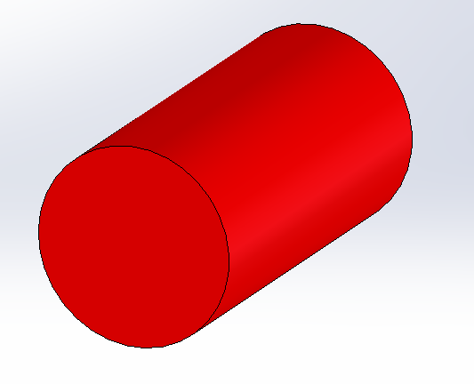
Tube in Tube Joint Overview
Tube in tube joints are one of the most common design structures. Whether round, square or rectangular these joints are everywhere. You don’t even have to use structural shapes for these designs and can make your own custom shapes.
Generally speaking you will want to have about a 3:1 overlap on the inside members height dimension when extended. This means that if I have a 5″ x 4″ tube, I would want the minimum overlap at full extension to be 15″ (5″ x 3). This will minimize play in the joint and minimize the contact forces on the tube walls.
You will also want to make sure that the overlap at full extension is at least 25% of the total stroke. This will maintain a fair level of stability in the joint.
If the design isn’t loaded when sliding, you can get away with eliminating wear pads and/or rollers. A music stand’s height adjustment is a good example of this. Round tubes are generally the best choice for these types of situations because the OD and ID of the tube are controlled. You can select tubing sizes to minimized play in the joint
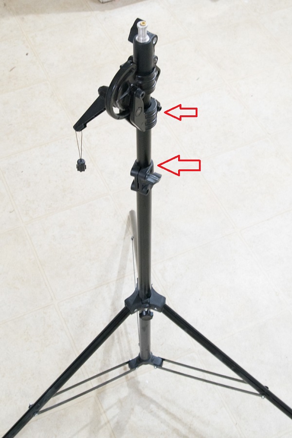
However, if the apparatus is loaded when it moves, this design will wear out very quickly, especially if it is metal on metal.
The main down side of using round tubing is you can’t prevent rotation naturally. You will need another mechanism to do that. This is where rectangular tubing comes in handy.
Square or Rectangular Tubes
Square and rectangular tube in tube designs will naturally prevent rotation of the inner component. Additionally, they give you a great surface to mount slide pads or run cam followers.
The major down side is the end of the tube will need to be reinforced. As the tube is loaded, the loads will tend to yield the end and cause it to look like the horn of a tuba. Not good! However, this is a proven design and it will work.
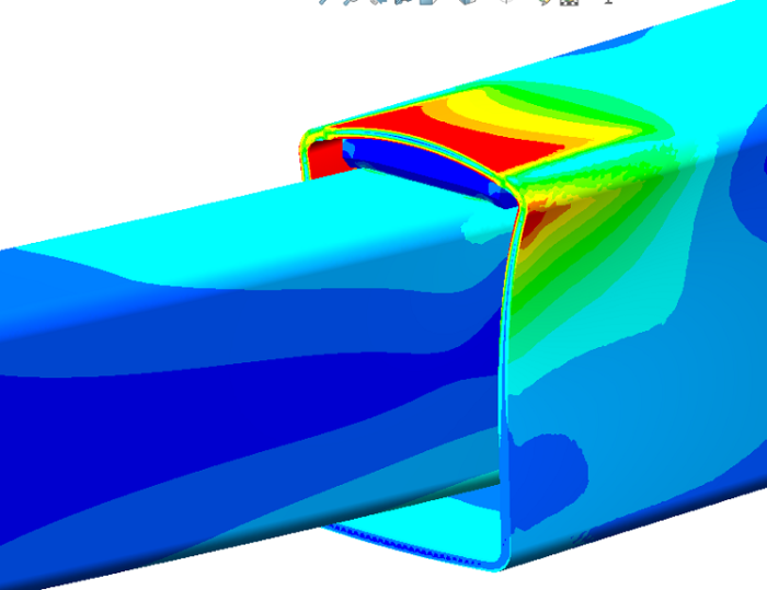
It works because once the material has yielded, it will redistribute the stress. In the initial loading, the material will bend. Since it is thin, there isn’t much resistance to bending so it yields and makes the horn shape. As the loading continues, the material starts to transform and the bending load converts to a tensile load and acts like a rope with constant stress throughout the material.
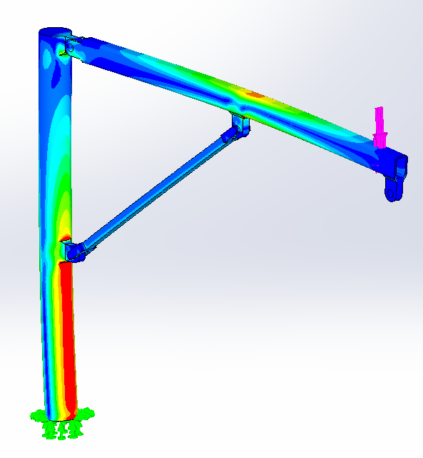
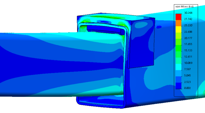
Reinforcement
While this, structurally speaking, will probably work for most designs. No one wants to walk up to a machine and see a horn shaped tube! It also makes the joint have a lot of extra play that can’t be changed. The solution is to reinforce the end of the tube.
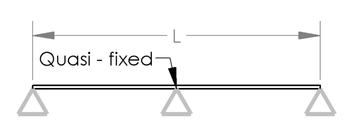
The first step to reinforcement is hand calculate the stress on the tube as if it is a simply supported beam with a load in the center. I choose simply supported because we do not want the sides of the beam intentionally carrying moment. The length of the beam should also be the maximum width of the tube.
I also suggest using a point load at the center not only because it will be easy to calculate but also it is the worst case. With slide pads, we can’t be assured that the pads will contact in the way we want. If there is a torsional load, we will be contacting differently than in pure bending. (More to come on that)
You may also want to reinforce the sides to deal with the extra load and amplify the stiffness. While we assumed a simply supported load, it doesn’t mean that it is simply supported. Those corners are still taking some moment.
Strengthening the Inner Tube
The contact forces between the tubes can be quite large. In the previous section, we discussed how to stiffen the end of the outer tube. Well, we are half way there. We now need to address the inner tube.
While we can add material around the outer tube of our sliding system, it is often more challenging to add material to the inside of of the inner tube. Quite often there is a cylinder in the way that makes structural improvements very difficult.
Another complication is if the outrigger moves under load or can extend to various positions. If either of these situations are in your design, you will probably need to add doubler plates under the wear pads for strength. To decrease the moment on the inner tube, you can split the wear pad and have the only the corners contact.
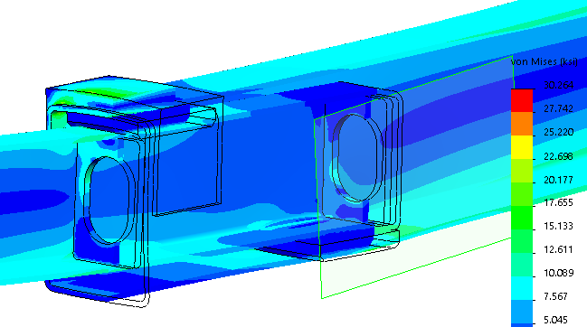
If your design is unloaded when it is sliding and always extended to the same place(s), you can add web stiffeners to the inside of the inner tube. The web plate is the best way to transfer the contact load to the side walls. An oval or slot shaped hole can be added to the center to allow a cylinder and any hoses or wires that need to travel with the sliding section.
1. Should I Use Wear Pads or Rollers?

Using wear pads or rollers is always a tough decision. This guideline should help you to make that decision.
As a rule, I always start my design with the intent of using wear pads. As the design progresses, I will keep in mind the following conditions and switch to some sort of roller system as needed.
Heat Generation
Wear pads are friction members. If extending under load, they produce heat! Since they are plastic, they can melt pretty easily. They need time to cool off in between cycles. I would suggest less than a 25% duty cycle on wear pads. Switch to roller bearings if the duty cycle is too high.
Also, the maximum speed of the tube is critical. Depending on your material speeds of up to 10 fpm to 25 fpm are acceptable. Experimentation in your application will be necessary.
OSHA Requirements
If this is an unpowered sliding system (meaning it is powered by a human being), OSHA has a lifting limit of 50 lb. While I am not sure if this translates directly to pushing or pulling items, I still think that it is a good limit to design for.
In design, I would plan on using only 60% of the 50 lb or 30 lb as the maximum limit that the operator will exert. Be sure to calculate the additional forces if this is used on a slope. This way when the unit is fabricated, you have some tolerance in the design in case the the tubes are tight and it requires more force than expected to extend.
To reach this goal, you may have to change from sliding wear pads to rollers. This move will add some cost and complexity, but it can drastically reduce the force required to slide.
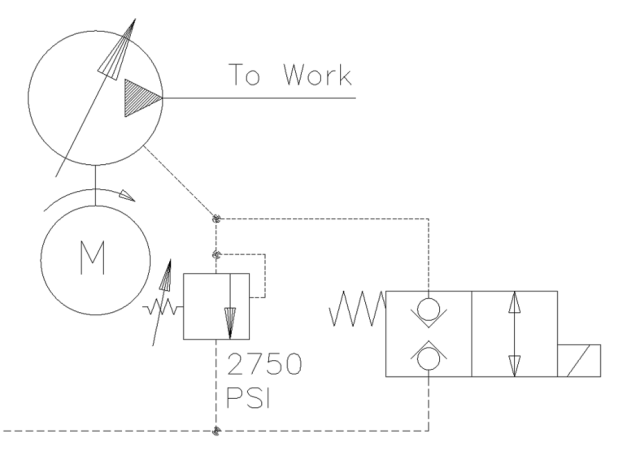
2. When to use Powered Extension
As mentioned in the previous section, I design to 30 lbs of force for the operator to apply to the sliding tube. If changing from wear pads to rollers does not get your force low enough, you need to make plans for powered extension. Another reason to switch to powered extension is if your system needs to slide while under any significant load.
The most common form of extension is a cylinder. They are inexpensive and pack a lot of force into a small area. Ball screw jacks, rack and pinion systems and cable drives are also popular options.
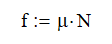
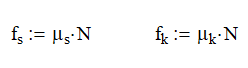
3. Contact Stress
Contact stress or Hertzian stress is a major concern in sliding joints. This is the stress that the roller (cylinder) exerts on to the tube (flat surface). With a flat wear pad, this calculation is easy; force divided by length times width. However, with a roller is a bit more complicated.
A wrong calculation here can leave divots in the flat surface, making a clunking sound every time the roller passes by.
This calculation is largely a factor of the diameters of the cylinders and the material selected. To get the maximum allowable contact stress use the following two formulas. The formula is based off of two cylinders contacting each other. Since we have a cylinder and a plate, we will make one of the cylinder have a very large radius.
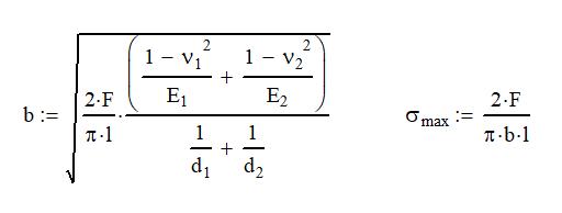
Where:
- b is the effective half width
- F is the load applied
- l is the length (width) that the two cylinder are engaged.
- v is the Poisson ration of the materal
- E is the Young’s modulus of the materia
- d is the diameter of the cylinder. Make one of these very large to simulate a flat surface.
- σmax is the maximum contact stress
When using this with other applied loads. The stresses will combine using the square root of the sum of the squares method. You will want to keep the non-contact loads to your standard design factor. When the load is combined with the contact stress, it should be less than the yield strength.
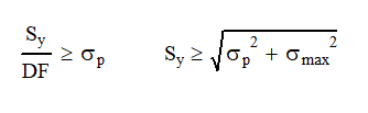
Where Sy is the yield strength of the material, DF is the required design factor, and σp is the principle normal stress of the other loads.
4. Planning for Load Reversal
I once worked on a project where every time the truck went over a speed bump, the lift part of the truck would raise up and then slam down in to the rest. Really loud!
After a lot of research, we found that the scissor structure below the lift was designed to hold the unit up and steady, but there was nothing to secure it in place when stowed. The design assumed that gravity would keep the lift in the proper place.
I share this story because it requires me to think about what happens when gravity is reversed or is 3 to 5 times what it normally is.
Trailers are an excellent example of this load condition. Road fatigue is the major obstacle when designing trailers because they routinely see 4 to 5 times their mass. Not many of us would normally use a design factor of 8:1 or 10:1 to overcome this obstacle.
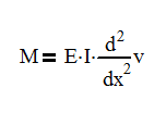
When planning for load reversals, we may also need to use much higher design factors than normal. This also gives another benefit; a stiffer system. All things are subject to Hooke’s Law. When you push or pull them, they act like a spring.
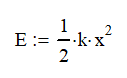
The amount of energy stored in the spring is subject to the equation above. If I have flimsy sections, my deflection, x, will be much larger and therefore store a lot more energy.
As a result, making the system stiffer reduces energy that can be stored. We want to minimize energy absorption because sound is a form of energy; and the one we are most concerned about in our sliding tube design.
5. Planning for Noise
No one likes to have a noisy machine. As engineers, we can design out many of the of the major sources of noise.
Noise from Roading
Roading is a term for mobile equipment that needs to function on the different road surfaces. A unit can make a lot of noise on one surface say dirt or gravel roads, but on highway can be super quiet.
Running on dirt roads is great source of load reversal. I just mentioned that if we stiffen the system we can minimize the energy stored that may get converted to sound.
Please note that stiffening the system most likely will lead to some weight increase, but it doesn’t need to be a dramatic increase. Make your sections taller rather than adding wall thickness.
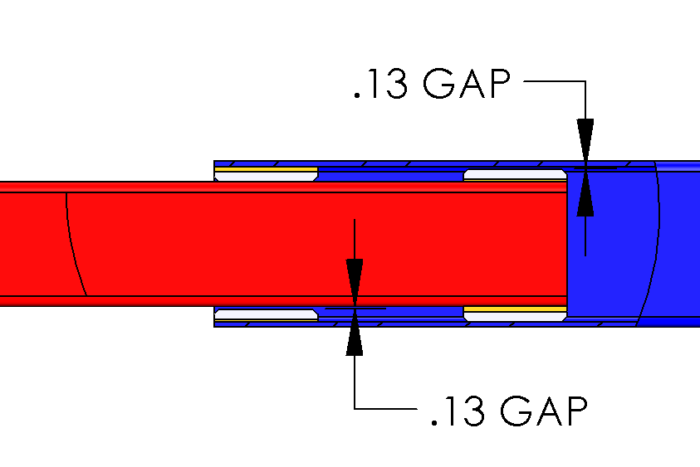
Minimize Gaps
In addition to stiffening the sections, we can also minimize gaps. Gaps by definition are places for potential energy to store. Minimizing the gaps is a great way to minimize sound.
If you are using wear pads, design sheet metal shims of differing thickness that can be used so that gaps can be minimized to 0.063″ (1.6 mm) or less.
If you are using rollers, start off with standard rollers and move to eccentric rollers if you need to. An eccentric roller is a cam follower where the roller and shaft are off center from each other. Rotating the shaft will allow your to increase or decrease the gap in your design.
Often times, you might find that the eccentric roller just doesn’t remove enough of the gap. This is why I always like using roller bearings in conjuncture with slide bearings so they can be shimmed.
Metal to Metal Contact
Metal to metal contact for sliding joints is undesirable especially if there are large reversing loads. Metal on metal not only wears the softer material quickly, it also makes loud noises when contact is made.
The only exception to this is with roller bearings on metal surfaces. While noise can be made on contact, you really do need hard surfaces for bearings to work well. The rolling action will reduce any affects the metal on metal joint will have.
Low Bearing Pressure
Noise is always an area of concern with slide pads. With sliding wear pads, the noise usually comes from a pad that makes light contact.
The Whale
At a previous job, we had an articulating cylinder that had two cylindrical bearings. One of the bearings was directly under the load needed to articulate the cylinder. The other bearing was equal sized but had nearly no load on it.
As a result, the no-load bearing sounded like a irate whale and could be heard from a quarter mile away. No joke…it was loud!
The solution was two part. First, move both bearings laterally a little so that the load was distributed better. Second we narrowed up the no-load bearing so that the pressure increased. The noise vanished!
Recommended Design Pressures
I tell the story so that you think about bearings in terms of the maximum and minimum loads while moving. In general, I look for the maximum contact pressure to be 10% of the tensile strength or a 10:1 design factor. I do this because I assume that only 50% of the pad is actually in contact with the mating surface and then add a 5:1 design factor so that the wear rate is minimal.
I also look for the minimum load on the bearing to be 2% of the tensile strength or 1/5th of the maximum allowable contact load. Keeping this minimum load in mind will increase your chances that noise will not be an issue.
One Trick for Minimizing Area
A popular way to mount wear pads is with flat head socket screws. So if your pressures are just a little bit too low on your wear pad, you can countersink the holes deeper than needed. Not only will it add head clearance for the bolt, it will reduce the area of the pad.
Improper Wear Pad Design
Noise can also come from improper wear pad design. Most design issues have to do with too large a wear pad area as we discussed. The next two leading issues are loose pads and improper fastening.
If your wear pad loosens up, you probably don’t have enough fasteners or they are located improperly on the pad. If you have a lot of noise on a wear pad, make sure that the fasteners holding it are properly tightened.
If the problem insists, look into the design. Start with evaluating if the force, usually shear, on the fasteners is adequate for the job. Look at the retaining method and head clearance. Many times lock washers or thread locking compound my be all that is needed to quiet the joint.
Next look at the chamfers on the slide pad. There should be a lead in chamfer of at least 1/8 inch in the direction of motion. The wear pad should also be longer (in the direction of travel) than it is wide.
Finally, be sure the fasteners are near the perimeter of the wear pad and there are at least 2 fasteners per pad.
6. Planning for Slop
Slop is necessary in every sliding joint. We don’t want our sliding joints binding up from interference when the tolerances are too tight. We also don’t want systems that are so loose that we can’t accurately control or that create noise or vibration every time it moves.
Chances are that you will not be machining every part in the system so we will need to plan our tolerances carefully.
I’ll illustrate why planning for slop in the joint is important by sharing one failure with you. This failure had a deep impact on the way I design sliding joints to this day.
My Critical Error
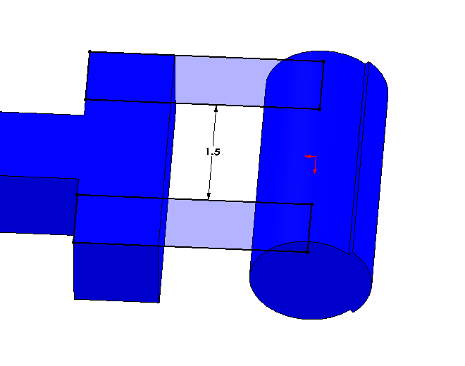
So this is the area that I made my critical error. As you can imagine, every sliding joint needs some slop or looseness in the system. We need to plan for that. Sliding on rails doesn’t require too much slop, but a tube in tube does (like 1/16″-1/8″.)
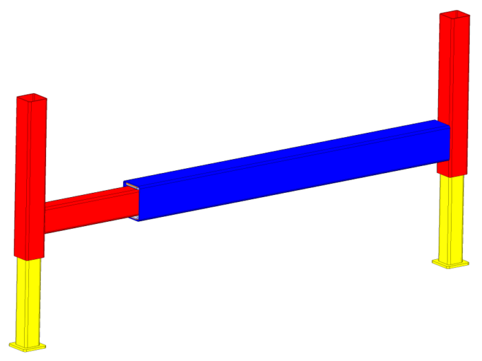
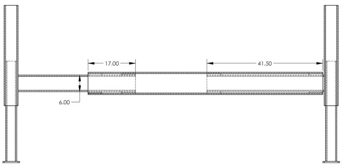
My error was that I didn’t plan for this in my tube in tube design. The unit had some “out and down” outriggers where the outrigger had a horizontal tube mounted to the vertical outrigger. The horizontal tube section slid in another horizontal section.
I designed the tube in tube section to have a good amount of slop so that there wouldn’t be any binding. Yea! However, I did not plan for the angle that this horizontal tube would be at when the outrigger was loaded.
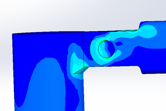
When the machine was set up, it looked like the outriggers were broken and about to fail. (However, it was still structurally fine.) Regardless, no operator wants to use a machine that looks like it is already broken.

The cause of this fiasco was that I wanted to minimize the effort by the operator and make the sliding action exactly level. This is somewhat humorous assumption because the operator will likely be setting up on a slope anyway. Once the outrigger was all the way out and started to deploy, the slop in the joint would shift the contact from the cam rollers to the wear pads in the opposite direction.
Result: Looks broken.
What should I have done? Easy, plan for the outrigger tube be horizontal when taking the load; not horizontal when sliding. To keep the same tolerance, I would need make it slide at a slight downhill angle when extending. This solution may now need to be powered or at least have an extension spring to help returning it to the stowed position.
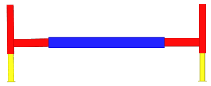
Right side is deployed under load. It looks well designed.
(Interesting side note: the solution to this is the only time I have ever used a 7/16″ screw)
7. Plan for Assembly and Maintenance
This is where most engineers make the big mistakes. Here are the major contributors to assembly and maintenance issues:
- Not thinking through how the unit is assembled – Oh boy has this burned me! Tube in tube joints usually have a specific way that they need to be assembled. You need to go through each step in the assembly process one component at a time and insure that each step can be completed. I’ve known many people who can do this in their head. For the rest of us, hiding parts in 3D CAD will do the same job.
- Wear pads are difficult to position – Make your wear pads come right up to the edge of the tubes. Not only does this make locating the screw easier because you know it will be flush, but it also increases the overlap of the tubes. Double win!
- Not leaving room to tighten fasteners – There is nothing more frustrating that tightening a fastener by flipping a combination wrench over each time or only hearing one click on a socket wrench. Design in more room please!
- Reaching inside tube really far – If you need to reach inside a tube more than 18″ to insert a part, something is wrong with your design. I do admit that I have had the occasional design where a bolt spring was needed to install a carriage bolt (see below). It is one thing to reach in to install a bolt, but another to have to hold it during torquing.
- Wear and Tear – Debris and rust can prevent you from removing fasteners. I like to avoid using socket head screws where possible because they are notorious for getting stripped because of rust of debris.
- Wear pad replacement – Your wear pads may need to be replaced from time to time. As you are assembling this, ask “How many parts need to be removed to swap out the wear pads.” It was always a requirement for me that the wear pads could be replaced by only removing a cylinder pin or other component. I liked to be able to slide the inner tube out the opposite end so that those wear pads could be replaced easily.
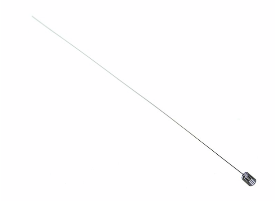
Image courtesy of etrailers.com
Conclusion
Tube in tube sliding joints are more complicated than they appear. There is a lot that goes into making a great sliding joint. This guide should be the first step in identifying critical aspects of these type of joints.