

On the first day of my high school physics class, our teacher stated, “If you don’t like solving problems, you shouldn’t be in this class.” Yes, the engineer’s main role is to solve problems. So if you want to be an engineer, you must love to solve problems.
To adequately prepare yourself for engineering school, you should take a college preparatory course load with a 3.0 GPA, have at least one STEM or community related extracurricular activity and have at least 680 Math and 530 EBRW scores on the SAT.

I own a shirt that says, “Engineer, solving problems you didn’t know you had in ways you can’t understand.” No matter what discipline of engineering you are in, you are solving a problem for someone. This is precisely what an engineer does, solves problems.
If you enjoy doing these following activities, you may want to pursue engineering as a career.
- Solving problems, puzzles, Rubik’s cubes etc.
- Thinking about new ways to perform tasks
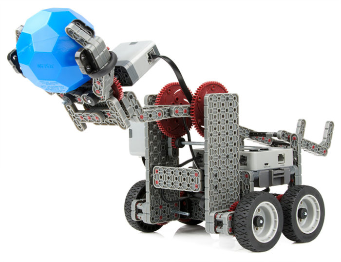
- Building with Legos
- Identifying and optimizing efficiency in day-to-day tasks
- Like being challenged. (I often declare, “challenge accepted” at off the cuff comments by others.)
- Have a thirst to know who things work.

Having the above desires and traits won’t make you an engineer. It takes a lot of work to become an engineer. I know several people who would make great engineers because they couldn’t (or wouldn’t) take the classes.
Conversely, I do know other engineers who have a degree who can do all the math and science given to them, but cannot solve a “real world” problem on their own.
Engineering Career Paths
Most employers are looking for a bachelor’s of science in engineering degree from a college or university. This is a 4 yr degree (or 5, like me) and opens the door to most opportunities. You can also proceed to get a masters or doctorate if you like.
Another option is a 2 yr engineering technology associates degree. These degrees are intense and cram 4 years of math, science and engineering into 2 years. College admissions here are a little more relaxed as far as what courses need to be on your diploma.
I have known many very smart and capable engineers who went this route. Some of them even went on to get their professional engineering license.
Academic Course Requirements
Any ABET accredited engineering school is going to require a high school diploma. But not all of them are equal.
A student might have a 3.9 GPA but only taken the minimum classes needed to get a high school diploma. Another student my only have a 3.0 GPA but has taken 5 years of math and 3 years of science as well as several honors classes.

Most colleges will see the the latter student as superior to the former because of the increased course load.
College Prep vs Diploma Requirements
The table below shows the difference between most states requirements for a diploma and what colleges expect from a college prep curriculum.
| Subject | Years | Diploma Notes | Years | College Prep Notes |
| Math | 3 | Algebra and Geometry minimum | 4+ | Algebra 1, 2, Geometry, Trigonometry, Pre-Calculus, Calculus |
| Writing | 2 | One may be part of another class | 4 | 3 Literatures and composition |
| Language Arts | 4 | English or Foreign | – | |
| Science | 2 | – | 3+ | Biology, Chemistry, Physics (with labs) |
| Social Science | 2 | US history required | 2-3 | – |
| Electives | 1 | Art, music, vocational | 1 | Art, music, vocational |
| Physical Education | 2 | Daily exercise all four years, .5 credit per year | 2 | – |
| Health Education | 0.5 | 0.5 | ||
| Consumer Education | 0.25 | 0.25 | ||
| Challenging Electives | 0 | 1-3 | Communications, Computer Science, Statistics etc. |
You can see that there is an increase in English, Math, Science and History. In high school, I took 5 years of math and English. This required taking two English classes freshman year (literature and composition) and two math classes sophomore year (Algebra II / Trig and Geometry).
This sounds overwhelming, but I managed to be successful. After all, this curriculum was well established by the school and I was not the only one to do this level of coursework.
Required GPA
As you can probably guess, not only is taking the harder classes important, but you also must do well in them. It can be difficult to do both, but hey, you’re a problem solver.
Most colleges require a 3.0 GPA. Occasionally, you can have a lower GPA, but you will need to show that you are still in the top 25% of your class. This can be difficult to do so strive to get better grades and have the minimum GPA at time of graduation.
Since more of the engineering related subjects are taken later in high school, some colleges will look at your transcript and if your grades improve junior and senior year, you can sneak in with less than a 3.0.
If are excelling in some core classes, try to take some AP (Advanced Placement) or IB (International Baccalaureate) classes to help improve your GPA because they are on a 5.0 GPA scale where a B grade is now 4.0 instead of 3.0.
What do I do If I am Not on a College Prep Track?
Yes, there is hope for you to get into engineering school. First, you will want to plan the rest of your high school years to get as many solid math and science classes in. Preferably to pre-calculus and physics if not further.
If you are just a little short of credits, there is another option. Depending on what grade you are in, you can actually dual enroll in both high school and a local community college.
Dual Enrollment
Dual enrollment allows you to take a college physics class while in high school. And YES, you get credit for both! Super Sweet!
This allows you to take extra classes on nights and weekends so that your high school transcript is complete and you now have some college credit.
While you are doing this, you aren’t going to have much free time in high school. You will already be in 6 meaty high school courses and 1 night / weekend course. That is a full load!
If you are in dual enrollment for physics, you will want to have taken calculus first. Concurrent enrollment is acceptable, but you may be at a disadvantage because you are learning too many new concepts at once. This is because engineering programs require calculus based physics. There is no purpose in taking the class twice.
Summer School
Another option to catch up is summer school. Summer school is a great way to catch up. I recommend that you take a math class in summer school because they are probably offered and math courses need to be taken in order.

Math classes build on each other so each is a prerequisite for the next. Algebra I needs to be taken before Algebra II, but Algebra II can be taken with geometry and trigonometry. Calculus builds on pre-calculus which requires Algebra II.
When coming up with a schedule of classes, you will need to keep these prerequisites in mind. This is why I suggest doing extra math in summer school.
Community College
If you have already graduated or it is far too late to get on course, you will need to enroll in a local college or thanks to the internet, take online courses from a college far away.
This is a great option because allows you to increase your GPA and take many basic college courses much cheaper than at a 4 year college. When you have the basic requirements done, you can transfer to an engineering school when accepted. If you took the right classes, they should transfer as well.
I do want to caution you here. When going to a local college after high school, life gets in the way. The desire to make money, get married and have children can derail your plans if you don’t have laser like focus. Before going to a local college, make sure you have a well developed actionable plan so that life won’t easily get in the way.
Challenging Electives
Engineering schools want to see electives in your transcript. Depending on your school, you can look into electives that fall into the following general topics:
- Computer Assisted Design (CAD)
- Drawing / Blueprint Reading
- Computer Science
- Electronics
- Robotics
- Any engineering classes
- Advanced math / science (AP Calculus, AP Statistics, AP Physics)
Some of these courses may not be offered at your high school. If this is the case, look at dual enrollment options with your local community college.
SAT & ACT Scores
Taking standardized tests is a major headache and source of stress. Unfortunately, it is one of the hoops we need to jump through to prove we can do certain things. In the end, it is a character builder, so buck up and do it.
In general, universities are looking for higher math scores on the SAT than EBRW ( Evidence-Based Reading and Writing ). EBRW was simply called ‘verbal’ when I took the test, but I now find that ironic since there was nothing verbal about the test.
For the SAT, you should target around a 680 Math and 530 EBRW to have a wide selection of engineering programs to choose from. A score of 680 in math puts you in the top 90 percentile and 520 EBRW is in the 50 percentile.
However if you desire to go to a ‘name brand’ school, your math scores will need to be over 750.
As far as the ACT score your goal should be a 30 math and science and 21 for English and reading.
Preping for the SAT / ACT Tests
The SAT is a not test of your intelligence, but how well you take the SAT. Don’t get angry and try to be smarter by learning vocabulary and higher level math. Learn to take the test.

Image Courtesy of Alberto G on Flickr
So I know that everyone learns differently, but I took some of those weekly classes to prep for the SAT. I’m sure they helped, but I know that I did not put the time in to get better results out.
The SAT is a not test of your intelligence, but how well you take the SAT.
I recommend that before taking a class, you should get a hold of many practice tests and do one each weekend. Make sure they are timed. After each, score them and look for patterns.
I noticed that I always missed the last few problems in both math and ‘verbal’ so I left them blank. As a result my score improved.
The other benefit is that by taking many tests, you will manage your time better and become familiar with the test format.
If you do this and don’t see improvements in your score within four tests, go get some formal help.
Extra Curricular Activities
Colleges want to see that you aren’t the person that only goes to school and gets good grades. They also want to see that you play well with others and have interests other than your studies.
Extra curricular activities look good on an application, but this will only get you 10% of the way. Don’t focus on this too much because your course work, grades and test scores will get you 90% of the way to an engineering program.
Sports – Maybe
I say ‘maybe’ because there are not many stellar athletes in the NFL that have engineering degrees. In fact, I had a friend in college who was on the college baseball team with a scholarship. During his sophomore year, his course load was so great that he couldn’t keep up with both engineering and baseball. He chose to drop baseball and focus on engineering.
My point is that sports requires a lot of time and so does a heavy course load. Most people can’t do both.
Don’t focus on extra curricular activities too much because your course work, grades and test scores will get you 90% of the way into an engineering program.
However, if you are in sports, it does show engineering programs several key things.
- You have self discipline
- You work well with a team
- You have good time management skills.
Other Activities
There are many other activities that show you are an engaged person in your community or school. Consider joining one or two of the following groups to round out your college applications.
- Any club that is STEM related
- Student body office
- Campus club like chess, computer, language, band
- Volunteer in your community / Kiwanis Club
- Boy’s and Girl’s Club
- Boy / Girl Scouts
- Robotics – Check out Vex robotics and how to start a Vex Robotics Team for Free!
- Community group for your hobby (search Facebook Groups)
- 4-H
- Model UN
- JROTC (Junior Reserve Officer’s Training Corps)
- Try getting an internship in the field you want to study. Consider it even if it is unpaid (I have had two internships where the only thing I learned was that I didn’t want to have that job.)
- Do something cool and unique that will beg the question on your college application. Example, I hiked the Appalachian Trail, camped in a blizzard or wrote an ebook.
Conclusion
From the moment you realize that you want to be an engineer, you need to figure out where you are and where you need to be. Almost none of us are in the perfect position to easily transition from where we are to our objective.
Don’t expect your transition to be easy. This will require work and lots of it. You are going to have to say ‘no’ to certain things that you want to do. Work and self discipline are great character builders.
You can do it. Come up with a plan of what needs to be done each semester or quarter in school and work the plan. Focus on the tasks that will get you 90% of the way to your goal. Work the plan until you reach your goal.