

Statically indeterminate beams are a difficult and sometimes impossible to get a mathematical solution. FEA has been overused in solving these types of problems because it will iterate to a solution.
Statically indeterminate beams or systems of beams simply have more degrees of freedom than static equations available. Often, having one more equation would make the system solvable. This overlooked equation is beam deflection.
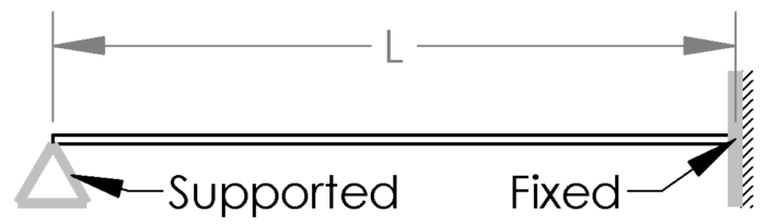
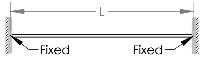
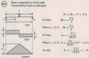
The most common (and simple) example of a statically indeterminate beam is a beam supported at each end and at least one of the supports can handle a moment. The two most popular examples are shown below.
For these cases, my Ultimate Beam Calculator can be of great service to you so I will not dive any further into it here. These beams use not only deflection to come to a solution, but also the slope at the fixed ends must have a deflection slope on 0° at the ends.
Using Deflection in Beam Systems
Unalike Beams with Load at Center
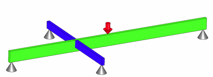
Beam systems are generally harder to solve, so we will focus there. The image below is a common situation of a statically indeterminate beam system. I will go into detail on how to step up and solve this problem using deflection.

The naturally available 6 equations are forces in X, Y, Z and Moments in the X, Y, Z. (This is where you use the right hand rule). There are no forces in the X or Z direction and therefore nothing to cause rotation on the Y axis.
Therefore, we are left with 3 equations, force in the Y direction and moments about X and Z. Unfortunately, we have 4 supports and is statically indeterminate. Or is it?
This is a case where we can use deflection to find out how the loads are distributed and what the moment on the beams are. When we look at a simply supported beam with a load in the center, we can look up the beam deflection in any table and find:
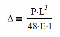
Where Δ is the deflection, P is the load applied, L is the length of the beam, E is the modulus of elasticity and I is the area moment of inertia.
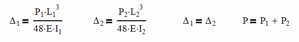
Since we have two beams, each will have its own equation.
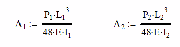
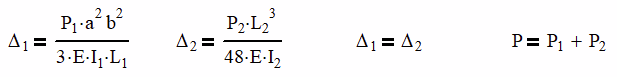
At the center where the load is applied, the deflections will be the same, causing the loads to be unequal. It is at this point, that we are able to come up with two new equations,
Δ1 = Δ2 and P = P1 + P2
The end reactions (A and B) on each support are also easy to find in a beam table.
Ra = Rb = P / 2
Combining these equations together can get us a workable set of equations able to find all of the reactions as well as the deflection of the beam.
Let’s run an example with the following parameters:
| P | 10,000 lb |
| E | 29,000 ksi |
| L1 | 72 in |
| L2 | 36 in |
| I1 | 5.33in4 |
| I2 | 1.30 in4 |
We can solve for the load and deflection on each beam and find:

Since the load at each end of the beam is half of the load applied, R1 is 1693 lb and R2 is 3307 lb.
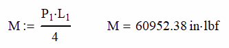
Finding the Moment
Knowing the load and the beam length, we can look up the moment on the beam in the beam table.
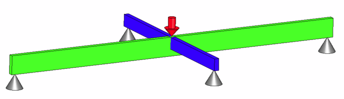
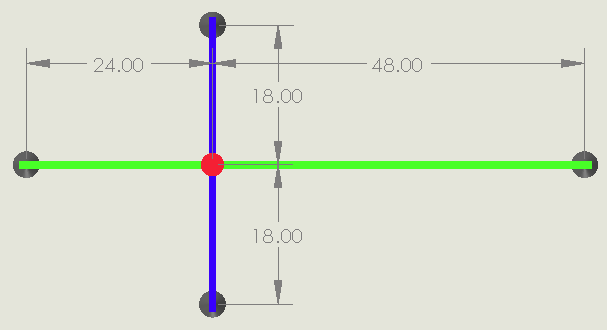
Unalike Beams with Load at Cross, but the Crossing Point Isn’t Centered

In this case, we have moved the crossing point 12″ off center with the dimensions shown below.
Here we have to use a different load case for the green beam, but the blue beam will remain the same. In this situation, the following equations still hold because the load is placed at where the beams cross.
Δ1 = Δ2 and P = P1 + P2
Looking in a beam table, the deflection of a simply supported beam with an off center load is:
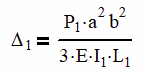
Where a is 24 in and b is 48 in from the dimensioned drawing above. Using the data from Table 1, we can now come up with our 4 equations and solve them.
The results are:
You can see, that moving the beams off center made very little difference to the process of solving for the indeterminate beam system. Let’s take the problem to the next level.
Unalike Beams with the Load Off Center
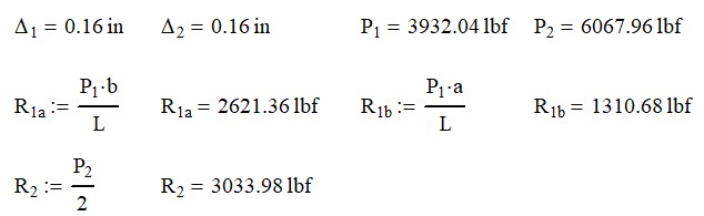
Now lets see what happens when the load remains centered, but the cross moves 12″ off center. First, our equation P = P1 + P2 is no longer valid because the load doesn’t interact where the beams cross. However, we still need the deflections to match where the beams cross. We will need to have the loads be equal but in opposite directions to remain in a static conditions. Thus, our equations become:
Δ1 = Δ2 and P1 = -P2
However, Δ1 becomes harder to determine and we now need to use mathematical principle of superposition to determine the true deflection. In this case, we have 2 loads acting upon the longer beam: the load applied and the load between the two members.
From the previous example, we have determined that the deflection at the cross is:
From the beam tables, we also know that the deflection of a simply supported beam with load at the center will be:
Since we are concerned with the deflection at the cross, we will set x = a.
Superposition At Work
It is here where superposition works its magic. Superposition simply states that with beams of the same L and end conditions the moments, end reactions and shear loads will add algebraically at any point along the beam.
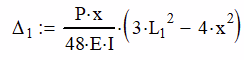
Furthermore, if the beam has a consistent cross section and material (E and I) the deflections can be added in the same way. For example, let’s use superposition to combine a beam with a point load in the middle (Δa) and one with an increasing uniform distribution (Δb).
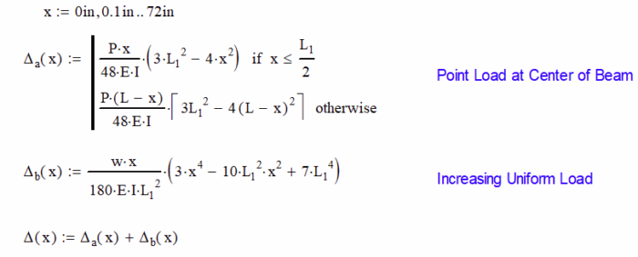
The last equation add the deflections together for each point along the 6 foot beam. The red curve shows the deflection from the point load peaking right at the midpoint of the beam as we would expect. The blue line shows the increasing load peaking just past the midpoint of the beam.
The green curve is the summation of the two loads. We don’t have to limit it to two loads, it can be many. In our case, we are interested in what happens at 24 inches (2 ft). Superposition – big word, simple concept to use.
Let’s get back to our problem.
We will employ superposition on the Δ1 equation where we will find the interaction of the beams in the first term. The second term will have the deflection of the beam at the point they cross from the applied load, P.

Note – if we didn’t add in the applied load deflection and solved, P1 and P2 as well as the deflection would have to be equal to 0.
At this point, we can solve the four equations above using the parameters in Table 1 and come up with the results as follows.
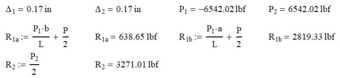
Notice how R1a and R2b now have two terms in the equation. The first term is for the interaction force and the second for the applied load.
One final thing that we want to check is to make sure that the reaction forces sum up to the applied load. I do this as a check just to keep me sane.
Here we find that when we add the reactions together, we get 10,000 lb which is what our applied load was. Yea!
Conclusions
This article gave you the tools to solve the 5 most common statically indeterminate beam cases. The first two are already well documented and can easily be evaluated with my Ultimate Beam Calculator.
The remaining 3 can be solved by using superposition. You can add loads and beams together and use deflection to figure out how the beams interact.
With enough time and patience, you can even work up a complex system of beams like what you see above. A system like this is still based on the steps illustrated above and can be solved by hand.