

So why do tripods have 3 legs, kitchen chairs have four legs but all office chairs have 5 legs? The answer is simple, stability.
Office chairs have five wheel because it provides the most stability with the fewest wheels. Four or three wheeled chairs would need to have very long legs to have the equivalent stability. Chairs with more than five wheels have added cost with little extra benefit.

Defining the System
The first thing that we will need to do is define the system. We can say from experience, that no one has ever flipped over an office chair over the front, but almost always over the back and rarely over the side.
As a result, we will focus on stability over the rear of the chair. To determine stability, one thing we will need to know if where the center of gravity (CG) of the person is. The center of gravity of a person is around center of mass at the height of the ‘bee bo’, I mean navel.
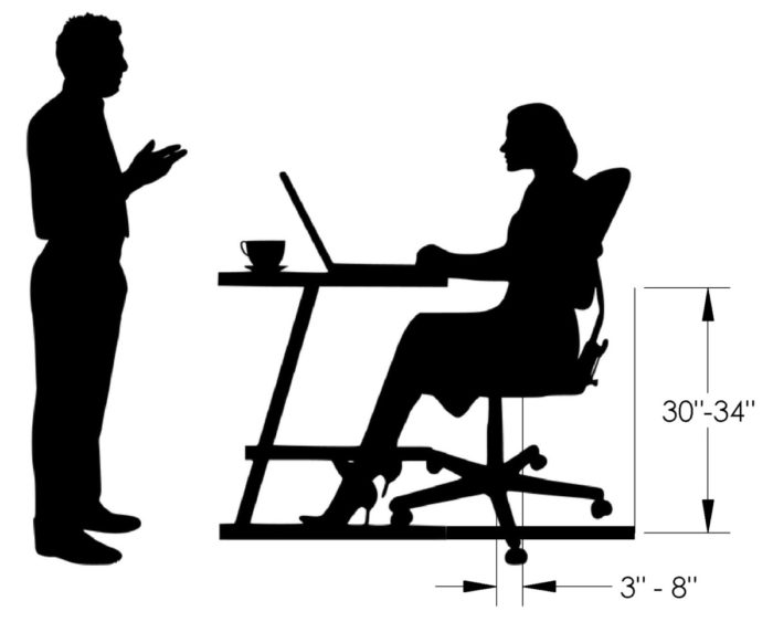
In the image above, a woman is sitting in a standard office chair. The height is adjustable so there will be a range of heights used in our calculation. We will find that the height to the CG is around 30″ to 34″ (76.2 to 86.4 cm).
Office chairs are also designed so that the center post is in front of the CG by about 3″ to 4″ (7.6 to 10.2 cm). This is done for a few reasons. First, it prevents creaking and swaying in the joints. No one likes a creaking chair and if the load is offset, it will always be in contact and rarely go over center which is what causes the swaying sensation.
However, the chair is balanced side to side so that if you shift your weight, you will notice some play in the chair design. Chair manufacturers try to minimize this because there is no other solution. If you put the post to one side, the chair will not move as easily when pushed by foot.
The second reason is that the post is in front of the CG is it allows the rider to control the movement of the chair easier. This is because we want the weight of the operator will be leading the chair’s direction.
The CG can also be extended rearward when you lean back or push your legs down to rock back. We could make the assumption that the body’s CG will increase to around 8″ (20.3 cm).
We can then add dimensions to our picture so that we can start making our Free Body Diagram
Dimensions added
Free Body Diagram
Case 1: Sitting in the chair
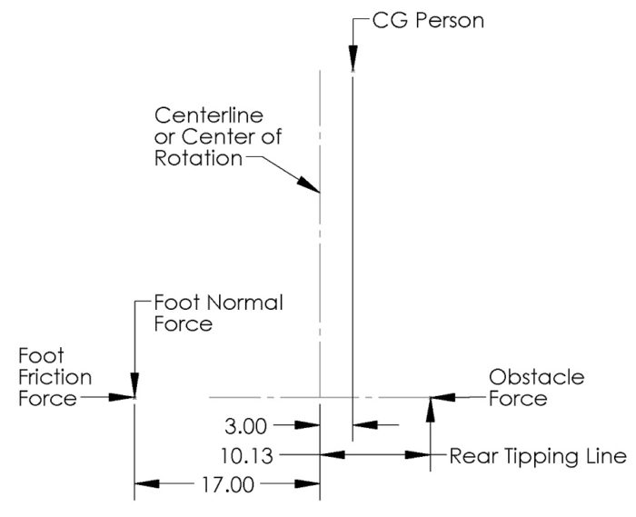
The diagram above shows the CG of the person and the rear tipping line. As you can see when we just have the weight of the user and no additional forces, the chair is very stable. The diagram above shows that the weight is clearly between the center post and the rear tipping line.
If you didn’t have confidence in the chair’s stability, we probably wouldn’t have sat down in it in the first place. No, the problem always happens when we start to move, shift weight and do other stupid things.
Case 2: Moving the Chair Backward into an Obstacle.
So this is the most likely way to make your chair tip over. So you are scooting your chair backward and you run into a jacket, purse, officemate’s foot or even the cheap plastic mat that your chair rolls on.
All of these items can make your chair less stable. Let’s put some numbers to an example. Let’s say that a 200 lb person encounters an object and 10 lbs of force will allow us to over come it.
The best way to approach this is to sum the moments at the rear tipping point and see if the moment is positive (meaning stable) or negative (meaning unstable). We will sum the moments with positive being a CCW moment.
The stability moment is the weight of the person from the tipping point. In this case it is: 200 lb x (10.13 in -3.00 in) or 1426 in-lb.
To find the Foot Normal Force we will need to make an assumption on the coefficient of friction between the rubber sole of your shoe and the floor. Depending on the type of shoe and floor material, I would guess that the coefficient could range from 0.2 to 0.7. Lower values will create larger normal forces, so we will use the 0.2 factor.
We can see that the Foot Friction Force needs to equal the Obstacle Force; 10 lb in this case. The Foot Normal Force can now be found by dividing the Friction Force by the coefficient of friction. The normal force will equal 10 lb / 0.2 or 50 lb.
We can calculate the moment that will cause instability by multiplying it by the distance to the tipping point. In this case, 17.00 in + 10.13 in. The moment is 1356 in-lb.
Is it Stable?
Well, we can subtract the stability moment from the instability moment. 1426 in-lb – 1356 in-lb = +70 in-lb. The chair is stable! You won’t fall over!
So Why Five Wheels?
Yes, back to the question at hand.
This question can be demonstrated far more easily with a diagram. The picture below shows the minimum tipping point of chairs with 3, 4, 5 and 6 wheels. You can see that as the number of wheels increases, the length of the leg decreases.

The reason we draw the line between the legs is when one leg comes in contact with an object, the chair will pivot (rotate) until there is a balance in force. This will be back to a static condition when a second wheel comes in contact with the object. At this point, the tipping line is the line between the two stuck wheels.
One other thing to note is that the wheels pivot on a location that isn’t at the center. This is so they are always lined up with the direction of travel. However, this off-center distance always works against us with regard to the tipping line. In the example above, I have already subtracted the off-center distance from the leg length.
Conclusions
We can see that having a three wheel chair is very impractical. We would need nearly double the leg length as a five wheel chair to have the same stability. This chair would be bumping into everything as we moved around and wouldn’t fit under most desks. Four wheels gets us close, but still it has long legs. On the contrary, going with a 6 wheeled chair only provides a slight leg length reduction, but would have a higher cost for the leg, wheel and center post design.
That is why office chairs have five wheels.


