If you’re interested in becoming a mechanical engineer you may be confused and overwhelmed because you are unclear of what a mechanical engineer does.
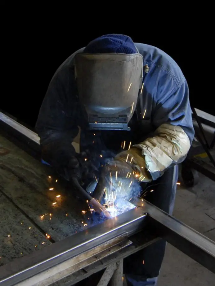
From a very early age, I knew that I wanted to design and build things for a living. This started when I was a kid playing with Lego. I really made some tall cranes and interesting machines. That is why I chose to become a mechanical engineer.
Mechanical engineers play a role in the design, production and distribution for nearly every product in you home. They design cars, airplane, robotics and industrial machines. They also research new materials and investigate failures and accidents. Mechanical engineers will also work with engineers of other disciplines as well.
First off, an engineer has nothing to do with driving a train! (much to my disappointment; I love trains!).
No, an engineer is a problem solver so you must love solving problems above all else.
Mechanical Engineering has the widest scope of any engineering discipline. With civil engineering, you know that you are going to work on roadways and bridges with a large emphasis on how they interface with the ground. Electrical engineers will work on electrical components.
The story is quite different for mechanical engineers. In school, you will study three main branches of mechanical engineering, thermodynamics, fluid mechanics and solids.
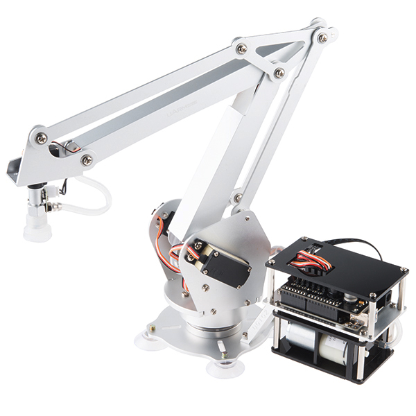
I believe that a fourth will be added within the next ten years, mechatronics. Mechatronics is the combination of computer science, mechanical and electrical engineering for use in integrated systems. Robotics and automation are great examples of how a mechatronics degree would be used.
With such a wide scope in mechanical engineering, no one can master more than one area and you can specialize in very small niches if you desire to.
Areas of Mechanical Engineering
Thermodynamics
Thermodynamics is the study of materials and how heat effects them. These materials are not only solids, but gases and liquids as well.
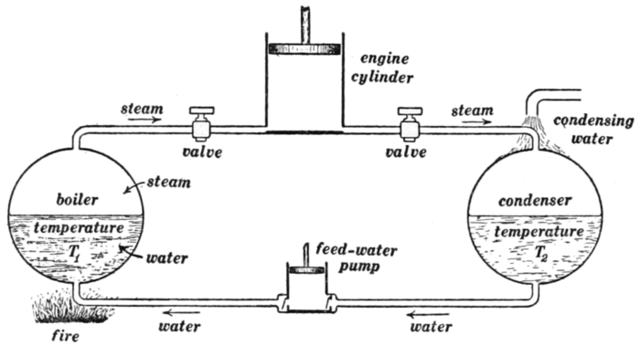
Engineers who use thermodynamics enjoy careers power plant design / management, HVAC (Heating, Ventilation and Air Conditioning), combustion or cyrogenics.
Fluid Mechanics
Fluid mechanics is a very interesting branch of mechanical engineering. We can probably guess that they study how water flows in pipes, but it in no way stops there.
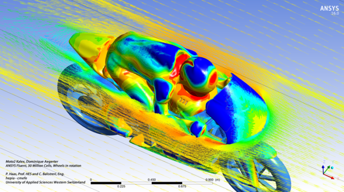
For me, it gets confusing when we consider how fluids flow over surfaces like a boat hull through water, airplane wings through air or a parachute coasting down to earth.
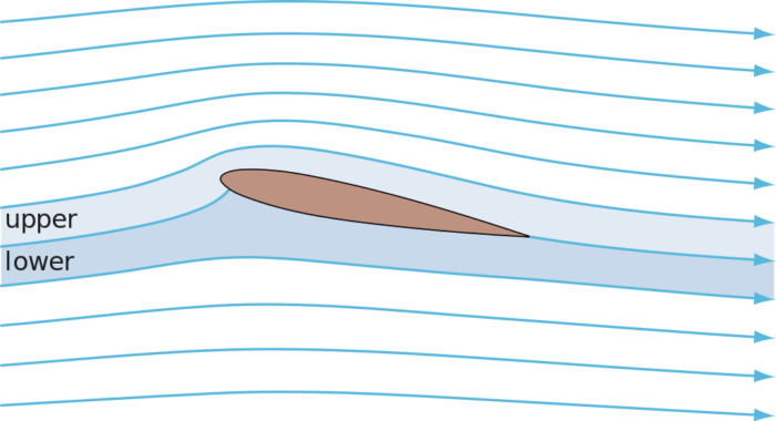
I’m totally lost when the fluid starts getting compressed and you can control the gases expansion in a combustion process to create thrust. Yes, fluid mechanics play a large role in rocket design.
Hydraulics is another large section of fluid mechanics. Many engineers that work with mobile or industrial equipment will cross over into this field to actuate mechanical functions. There is a lot of design effort that goes into designing valves and valve systems.
Solids / Structures
Solids is a very vague term to discuss this part of engineering. It is sometimes called structures, but that is also misleading because it is often confused with structural engineering. That is the structural design of permanent things like buildings and bridges.
This is my area of expertise and it generally can be defined as anything that is solid in nature, but not permanently attached to the ground. Good example are automobiles and other types of mobile equipment, industrial machinery, tools, alarm clocks, computer cases, metal furniture etc.
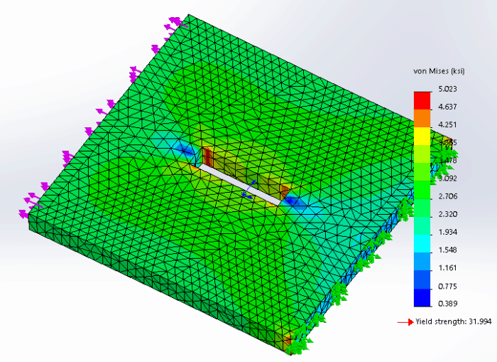
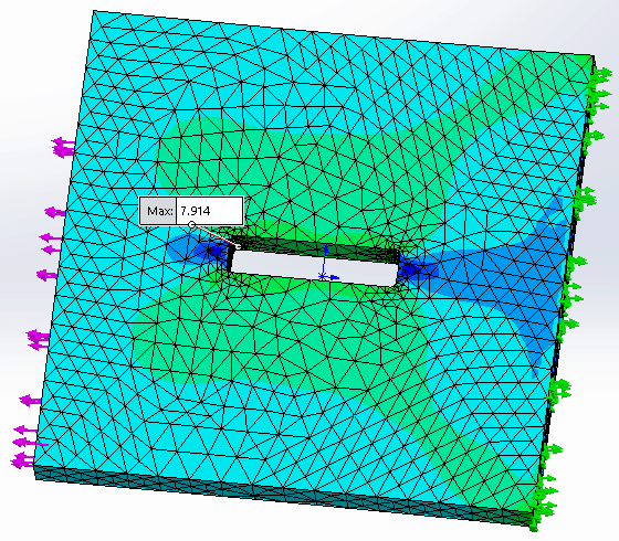
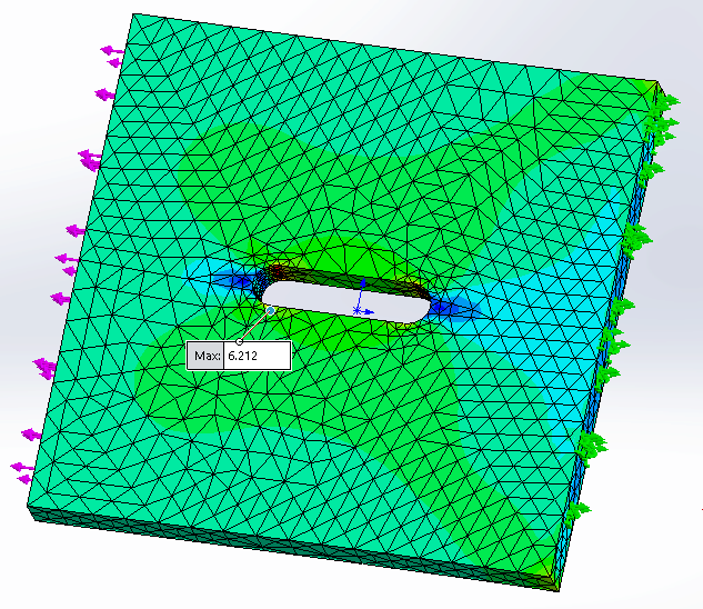
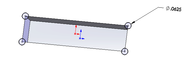
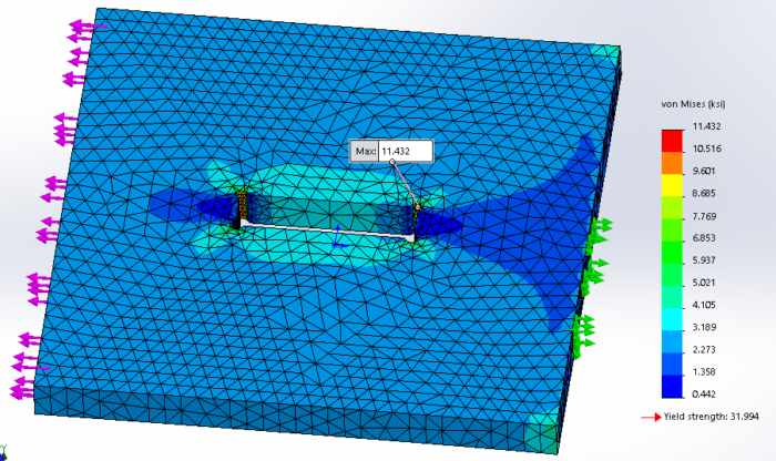
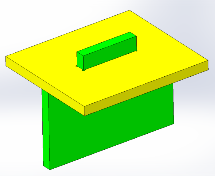
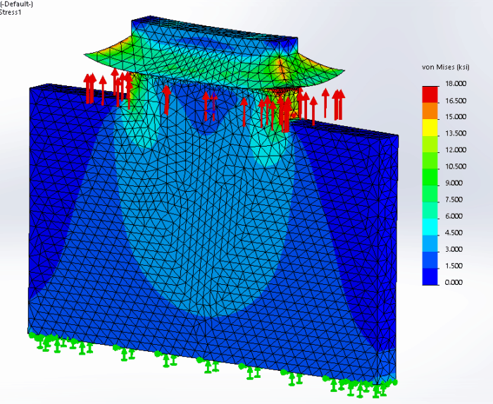
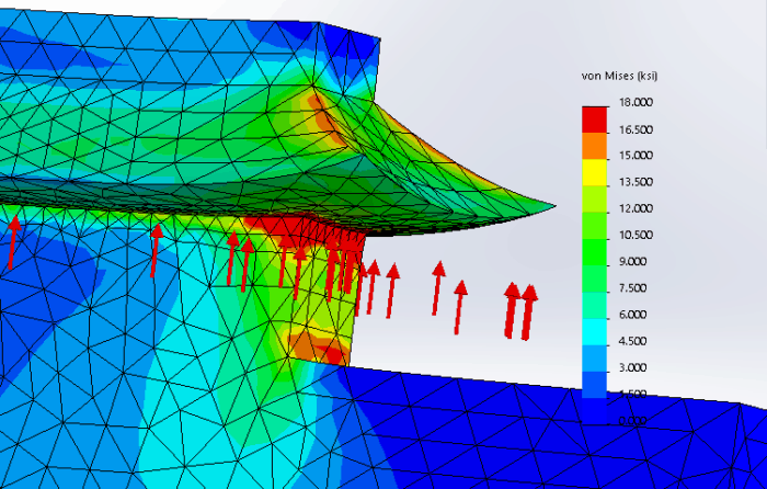
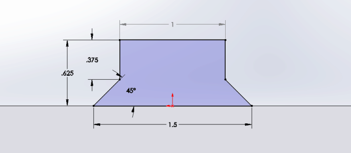
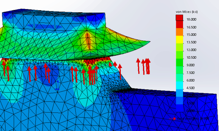
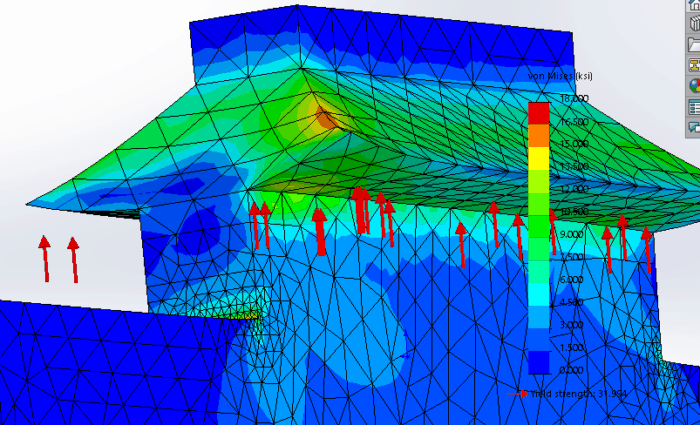
A solids engineer will evaluate stress and strain on an object and determine if it will break or not. Often times, the engineer will need to estimate loads and load cycles when they are not clearly defined.
Mechatronics
Right now, it appears that mechatronics is an engineering discipline just for graduate school. You may be able to take some electives for your undergraduate degree.
Mechatronics will be a growing field of study for years to come. The ability to design both electrical, computer and mechanical systems is only at the beginning stages.
One area of mechatronics is the IoT or Internet of Things. This is the technology that allows us to remotely start and stop our cars, lock the doors on our house and check on our kids when they get home from school.
One large subset of the IoT is the Industrial IoT (IIoT). This applying sensors to machinery to determine machine up time, report signs that parts are worn out and need to be replaced etc. Since more and more production will be automated, keeping machines running at full capacity will be critical. We will need lots of engineers to keep these running.
Career Paths
1. Design
So the design engineer is probably the most prominent and sought after roles as an engineer. Everyone wants to design something! A design engineer will need to be able to brainstorm, conceptualize and bring multiple systems together to work as one. These are not easy tasks.
A good design engineer will need to be good with all types of stress calculations, analyzing stress flow and finding ways to approximate things that are impossible to calculate. Another necessary skill is to be able to mentally see how a design works in time (the 4th dimension)
2. Testing
The testing engineer is the design engineers worst foe and the company’s best insurance policy. No one wants to launch a product that has a fundamental defect or doesn’t operate as intended.
Test engineers are responsible for examining products and / or software and finding ‘real world’ ways to break them or at least make sure they will last for the intended lifespan.
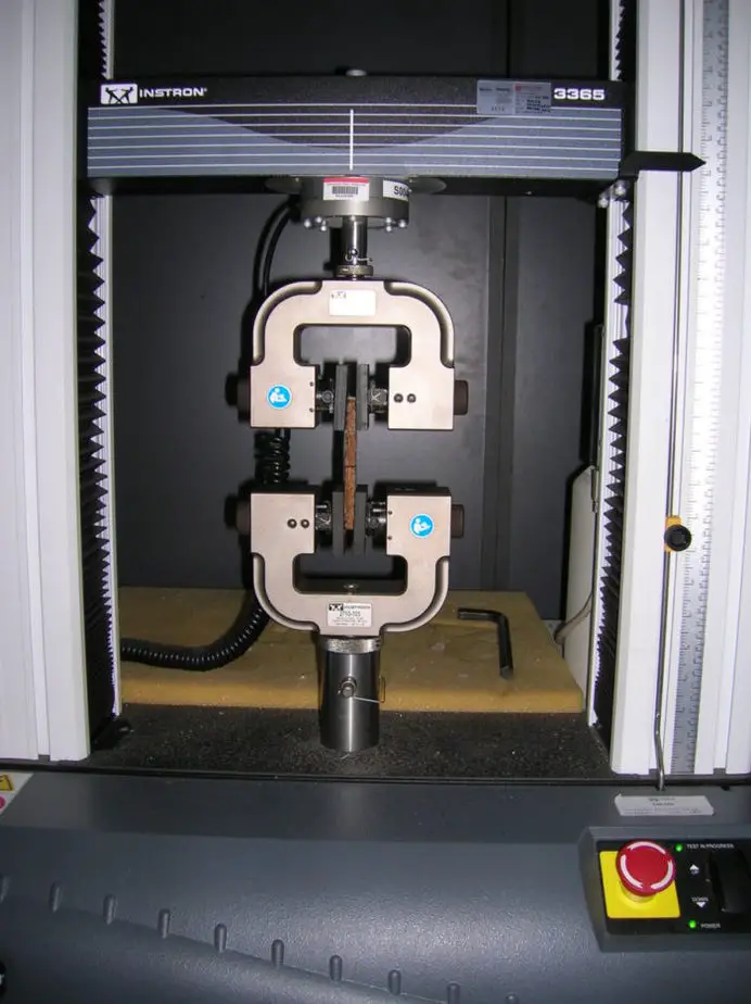
Test engineers will need to develop methods of testing products that may require high loads or cyclical loading patterns. You can also find out how to test for operation in high / low temperatures and weather conditions (mostly water).
3. Sales
Once you have a product, you need someone to sell it. Sales engineering will meet with customers to determine what the customer’s goal is and to suggest products that will solve their problem.
An engineering background comes in very handy here because you be able to grasp a full understanding of the product and what the customer wants to do. If you don’t know how a particular part of the solution would work, you are more likely to be able to identify this and bring others in who can answer the question.
If a non-technical person is in this role, you may sell a lot more product at first, but if it doesn’t meet the customer’s goal there won’t be any repeat business. You always want to make the customer have a pleasant experience so having a sale engineer is often the better choice.

4. Applications
Because of the complexity of equipment that is on the market, many mid to high end product are not purchased, but applied. This is where the applications engineer comes in.
The engineer will usually meet with a customer and salesman and do a thorough investigation of what the projects goals are and how to accomplish them. They will ask probing questions to make sure that the potential product is exactly what the customer needs.
After the sale, the applications engineer will customize an existing product(s) to the customer’s requirements. Sometimes these solutions will be fairly intense. The end result is a system that will not only meet the customer’s expectation, but it will also be a complete solution.
Applications engineers usually like this position because it allows them to meet with real people and get away from the desk. Applications engineers that interface with customers on a regular basis usually have a good idea of where their industry is headed.
Good examples of systems that are applied and not purchased are valves and valve systems, electronic control systems, fabrication machinery or any other product that has a multitude of options.
5. Investigative
An investigative engineer will travel to locations where accidents have occurred. These engineering can work for a private company, an insurance company, law firm or government agency.
The engineer will gather information from the accident and try to determine the cause of the accident for the purpose of trying to prevent it from occurring again.

This an exciting area of engineering because one failure will teach you more than a thousand successes. If you want to be an investigative engineer, you first need to be competent within your discipline and you better like flying, a lot.
6. Inspection
Similar to an investigative engineer, and inspection engineer will travel around, usually more local, and inspect building, construction sites etc. I generally get an email every quarter asking me to become a roof inspector for commercial buildings
Unlike an investigative engineer, the purpose of this position is to make sure that OSHA and building codes are being met so that there, hopefully, isn’t a need of an investigative engineer later.
7. Research and Development
Research is a critical part of sustaining a business. Many businesses are profitable for a time and then the market shifts leaving them broke. Having a team of research engineers and keeping an eye out for market shifts is important.
Many engineers are interested in being researchers because they will always be on the cutting edge of new technology. The greatest opportunity for a mechanical engineer in this field is in the mechatronics and materials arena.

Development is a slightly different from research even though they are usually lumped together in the R & D department. Though they are lumped together, they are not the same. I am a strong developer, but a so-so researcher.
A developer will usually build on the fundamental blocks of the research engineer and take a new product from a concept to production. This type of work has (hopefully) clear objectives, a firm timeline and project managers.
A developer is responsible for making sure that a company is putting out products that will keep them in business many years in the future.
8. Management
The general career path of an engineer starts in the weeds doing more technical work and tends towards management. Generally speaking, it earns more money and at the rate that technology changes, it is difficult for even the most eager engineer to keep abreast of it long term.
There are two main types of managers within engineering, people managers and project managers.
People managers will oversee other engineers and drafters in a department. Many engineers may thrive here but the opposite is true as well. It is always a benefit to have a manager that is an engineer because he or she can relate to the team on a technical level. They also should have better communication skills to relay information to management and customers.
Project managers (PM) are there to keep projects on time and in the money. PMs love Gantt charts and checking bank statements to know when a project is behind or over budget (they all are).

Having a PM that is an engineer is a big help to the development team. I once had a non-technical PM who routinely pulled me aside to ask me basic technical questions. Great every once in a while, but annoying when it is three times a day on a two year project.
9. Consulting
Once you have gained enough experience, a professional engineering license and a ton of contacts, you may think about starting your own consulting firm like me.
Consulting allows you to step out of your main industry and help others with their problems. Some companies just don’t have the knowledge resource or the man hours to start or finish a project. Many projects get dropped if they are small when they run into a technical blip.
As a result, many clients only need a few hours of your time to solve their problem. Other clients will want to hire you full time.
I like consulting because it allows me to work on a variety of different types of equipment and meet with people more. However, the down side is that you have to find clients and manage the entire project process. I highly recommend outsourcing part of this work to a virtual assistant (VA).
In Summary
Mechanical engineering is a very wide discipline with many unique ways to have a successful career. There really are no limits except for the limit you put on yourself.