

It is often the case that my beam is loaded in a way that is not in a design table. So what do I do?
There are several approaches to calculate beam moments when your load case in not in a table:
- Calculate Your Beam Loading from Scratch
- Simplify the Load to a Case in a Table
- Oversize the Load and Use a Known Case
- Add Several Cases Together from the Table
I’ll explain each in greater depth.
Calculate Your Beam Loading From Scratch
This is by far the hardest method of calculating moments or deflection on a beam. Don’t reinvent the wheel! We are smart engineers, let’s do what we do best: make assumptions and choose one of the other alternatives.
There are a few cases where we might need to derive our own formulas. The prominent one is a case where we are interested in deflection but our beam has a tapered cross section. Another case is where we have a beam deflecting under its own weight, but it has multiple cross sections. In these cases, we will need to refer to the beam deflection equation:
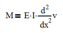
Where M is the moment, E is Young’s Modulus, I is the area moment of Inertia and v is the vertical deflection.
So….Avoid choosing this option wherever possible. The math just isn’t worth it.
Simplify the Load to a Case in a Table
Simplifying a load is often a quick work around. When I first started out as a design engineer, I sized pins by using distributed loads around cylinders and bores. This took a much longer time to calculate and lead to headaches. A few years back, a colleague challenged my approach and I’m glad he did. We both worked a few problems my way and his way. We ended up with the same results either way. Since then, I have reformed to doing it the much simpler way.
So my first suggestion is to treat point loads as point loads. I tried to treat them as distributed loads because they acted on a several inches of the beam and not just a point.
My next suggestion is to try to simplify constantly distributed loads to point loads and parabolic increasing loads to linearly increasing loads.
Many distributed loads increase, but don’t start at zero. In this case, separate the loading into a constant distribution and a linear or parabolic increasing load from zero. The magnitude of the constant distribution will be the smallest value of the variable distribution. Then subtract that value from the variable distribution.
Finally, can you ignore or combine certain loads? Often, the weight of a structure can be ignored. Or perhaps the weight can be combined with a load at (or near) the center of the beam.
Oversize the load and Use a Known Case
Similar to the previous suggestion, oversizing a load can give quicker, but less accurate results. Often times, I am just looking for a quick go / no go calculation in a meeting and need a rough answer quickly. Oversizing a load and applying it to a known (often memorized) load case gives me the ability to give one of three answers within minutes: yes, no or more analysis is needed. As a rule of thumb, I am cautious when giving a ‘Yes’ answer. For this to happen, I generally want a design factor of over 5:1 on a ductile material. ‘No’ comes a little more freely from my lips and that is reserved for anything less than a 1:1 design factor. The ‘more analysis needed’ answer comes for things in between.
In order to quickly perform these calculations I would memorize these formulas:
Cantilevered beam with point load on end: M = P * L
Cantilevered beam with distributed load: M = w * L2 / 2 or M = P * L / 2
Simply Supported beam with point load: M = P * a * b / L
Fixed beam with point load at center: M = P * L / 8
M is the resultant moment, P is the applied point load, w is the distributed load, L is the beam length, ‘a’ is the distance from one end to the load and ‘b’ is the distance from the load to the other end.
As mentioned, this method will give you a quick answer, but the results won’t be as accurate. Please use this method with caution and always perform a more in depth calculation before proceeding with a design.
Add Several Cases Together
So I saved the best alternative for last. Beam calculations can be added together by using simple algebra.
Let me explain and then we will run through an example. The first thing that I will want to do is select the proper end conditions. As I apply multiple loads to my beam, they all must have the same end conditions. There are six basic end conditions that you will find tables for.
- Fixed at one end, commonly called cantilever
- Fixed at one end and guided at the other
- Simply supported at each end
- Fixed at each end
- Fixed at one end and supported at the other
- Simply supported with overhang
The next step is to isolate all the load cases. This could mean all point loads, distributed loads and moment loads. Each one will need to be its own load case.
Once that information is determined, points of interest will need to be determined. For a cantilevered beam, this is most likely at the cantilevered end. However, there may be other points of interest if the beam has a tapered cross section. Depending on your loads, there may be 3 to 7 points were you want the moment calculated. I typically label these points with uppercase letters and skip I, L, M, O, P, Q and R because they are already used in calculations or easily confused with numbers.
Now here is the hard step, you will need to calculate the shear and moment at each of the points you have selected for each load case. Many tables have information on the moment at key points, but you will need to find a table that has the moment as a function of the distance across the length. For example, my table for a fixed beam with an offset point load doesn’t give me an equation for the moment all the way across. It does give it to me for the length from the left support to the load, but not the other side. This can make it very difficult to find the moment for all cases on all points. I use the numbers for each load case starting with 1.
At this point, you can simply add all the Moments at each point up as follows:
MA = MA1 + MA2 +…+ MAn. Easy Peasy.
Likewise, shear forces add the same way:
VA = VA1 + VA2 +…+ VAn
And deflections too!
ΔA = ΔA1 + ΔA2 +…+ ΔAn
Once you get all these things at point A, move on to point B and C and…. You get the drift. Before I move on to an example, be sure to watch your signs. Generally speaking, point loads consider down to be positive. If you have an up load, note it with a negative (-) sign! Moment loads can also be tricky. A clockwise moment is generally positive.
One note of deflection: many cases only have the deflection for certain cases and for critical points. While you can add deflections together, it may not be worth the time to figure out what the deflection is over the entire span of the beam.
In another article, we looked at combining a bunch of loads on a traffic light cross arm. Please refer to that as an example of adding multiple sections together. I want to do another example with different supports.
Example
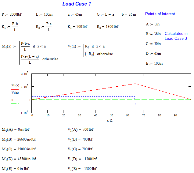
As an example, we will have a 100 in long beam that is simply supported at each end. We will put a point load of 2000 lb at 65 in, a distributed load of 80 lb/in from 25 in to 45 in and the weight of the beam at 4 lb/in.
By inspection, we can pick out a few areas of concern that we will select for calculation. First off, each endpoint will need to be looked at. For the point load it will be at 65 in. The weight distribution will be at the center, which is 50 in. The segmented distributed load is a little trickier. If using a constant cross section, we know that the deflection will be highest where the moment is highest. According to our table, that is at location a+R1/w and we will calculate that value a little later.
So, our points of interest are: A = 0 in, B = a+R1/w, C = 50 in, D = 65 in and E = 100 in. We will calculate the moment and shear force. Since A and E are reaction points, the moment and deflection are by definition non-existent, but we will calculate the shear reactions.
Now let’s get started. We will want to keep our three cases separate. They are shown together in the top view with points A-E labeled. Then they are separated into their individual load cases. (All table images are courtesy of Blodgett’s Design of Weldments published by Lincoln Electric. You should own a copy. Visit mentoredengineer.com/resources to buy and for other reference materials)

Load Case 1
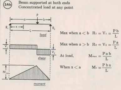
This is a simply supported case with a non-centered load. The load is 2000 lb at 65 in. The formula for the moment as a function of x, Mx, is only given from until x is less than a. To solve for this, I reversed my reference and started counting my moment as a function of y starting from the right, My. The moment equation is M = P*a*y/L. If I declare that y = L-x, I can substitute that into the original equation and get M = P*a*(L-x)/L. This is a technique that can be used in many cases and needs to be in your engineering tool belt.
Another thing to note is that the shear forces are negative on the right side. This is true, but keep in mind that the force from the reaction, R2, is upward and brings the shear force back to 0 lb. Remember to invert that force when calculating reactions.
We will now turn to MathCAD to calculate the moments and shear forces at all five points of interest. You can see that the highest moment is at point D, which is why we selected it. Also note that the magnitude of shear forces sum to 2000 lb and the moments at each end are 0 in-lb. These are good things to check for each case.
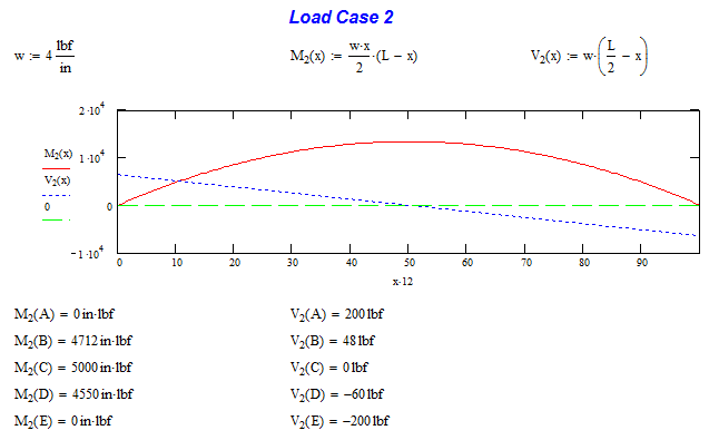
Load Case 2
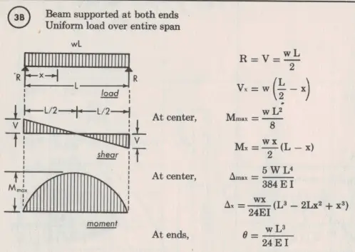
Load Case 2 is the distributed load caused by the weight of the beam. Its contribution will be minimal to the overall design and that is why this component is often ignored. The interesting thing about this loading is the shear stress is always decreasing. This leads to a constant parabolic shape of the moment curve. This load case is very easy to calculate because it is a continuous function.
When we go to MathCAD, we can see that our moment are 0 in-lb at the ends and the shear forces equal the loading of 4 lb/in * 100 in. Our highest moment load is in the center as we expect it would be.
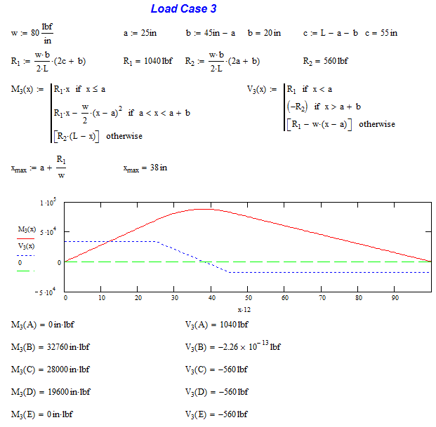
Load Case 3
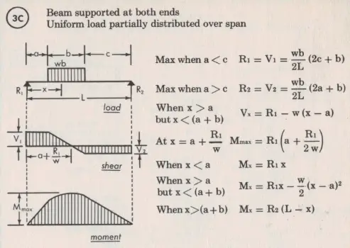
Load Case 3 is the most difficult because there are three portions of the curve that need to be analyzed. The shear stress is constant when x is less than ‘a’ or greater than ‘c’. It is linear between ‘a’ and ‘c’ and linear between the two. When integrated to get the moment, the slope will be linear up to and after the load and parabolic for the load.
I want to point out here that as the distance b decreases, the plots and formulas represent the case of a concentrated point load. Often times, a segmented distributed load can be approximated as a point load if b is small in comparison to the overall length. The moment will end up being a little higher. Conversely, if you have a large point load, you can distribute it to lessen the moment induced to the beam.
It is in this section that we will calculate location B which occurs when the moment is highest. This occurs at x = a +R1/w or 38 in.
Once again MathCAD confirms that the moment and shear forces check out at the end points. The maximum moment is at location B, just as the formula predicts and by definition, the shear is 0 lb. (If the shear force was other than 0 lb, it would indicate there was more area under the shear curve to add to the moment plot)
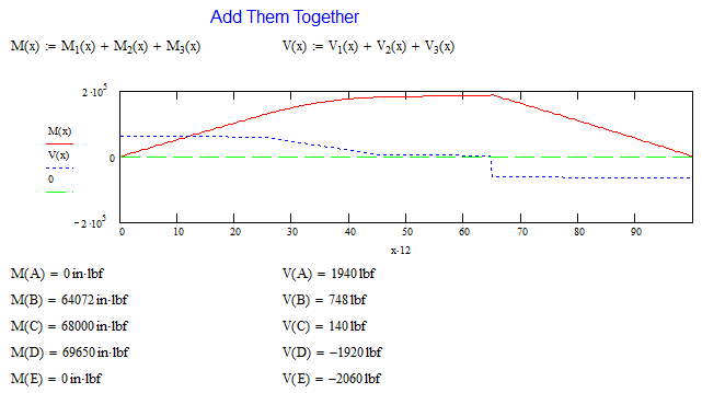
Putting it all together
The last step is to sum all the individual components together and determine where the maximum load is. In this case, point D has the highest moment load and near the highest shear load. This would be the prime candidate for structural analysis. Now, it looks like there may be multiple locations to check for high stress. If you have a shear plot, we can see where the shear load is above or below 0 lb. If it is above, moment will continue to increase. Once it turns negative, moment will start decreasing. In this example, the shear load does not cross 0 lb until 65 in. This way we know that this is the maximum load point.
Conclusion
Well, beam analysis is a tough subject. As you can see from the graphs above. There is no loading case on earth derived for is case. There are many ways to approach a beam loading that is not in any tables. The easy way is to combine simpler loadings from the tables into a more complex one. An even easier way is to use my beam calculator have it do all the work for you.