There is hardly a week that goes by where I don’t need to calculate the stress on a beam. Beams are everywhere and come with the challenge of many different loadings and supports.
There are 5 steps to calculating the stress on a beam:
- Determine the loads
- Determine the support conditions
- Draw a shear-moment diagram or look up in a table
- Calculate the section properties
- Calculate the stress and apply design factor.
With these five steps you will be able to setup and calculate most beams. With a little practice, you will be able to go through the steps with ease and greatly reduce the time it takes to calculate the stresses.
Let’s dive into each step with more detail!
1. Determine the Loads
This can be the most difficult part of the process because sometimes the loads are unknown or the angle changes with respect to the beam with time. Perhaps there are many loads that occur on the beam, but at different times. With each case mentioned, we are going to have to make some assumptions.
This can be overwhelming! I know because on the equipment I used to design, for each major component there was on average four positions it could be in and a side load component could be applied in two directions (so 8 cases total). My beam calculations for this were very thorough, but exhausting. Most importantly, they were worth it. There were two cases that fought each other making it difficult to come up with a solution. If I had not done the analysis on all 8 cases before testing, we would have had costly delays in testing and a longer time to product launch.
If the loads are unknown, is it because they are working loads or abuse loads? In some abuse conditions, it is possible to have the design factor account this. What is the design impact of using a worse case load? Would my section need to be increased much, if at all? Could I reshape a stiffener or gusset to carry the extra load?
If load angle to the beam is a consideration, choose the loading that is more perpendicular to the beam. The beams are much better with axial loads than moment loads. As a result, a load more perpendicular to the beam axis will have the greater impact.
If you have multiple loads that change over time, you will need to have multiple cases. This can be tedious, but it will pay off in the long run. Once you have all the cases, usually 2 or 3 stick out as ones that need to be monitored.
Load Types
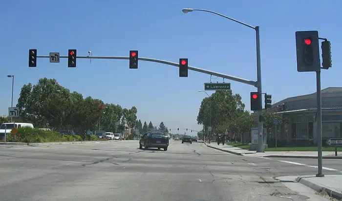
There are three types of loads that can be applied to a beam. They are point, distributed and moment loads. Point loads are the most common because they are applied to a beam at a very small location with respect to the length of the beam. If we considered a traffic light reaching across multiple lanes of traffic, there could be several point loads from the traffic light assembly.
A distributed load is a load that is applied over a wide span of the beam. The load applied with force per unit length and generally is lb/in or lb/ft (watch your units here). It may be applied over the entire beam or a small portion of it. This is a good method of simulating the weight of the beam. The load does not have to be equal over the entire span, but can increase or decrease from one end to the other. In our traffic light example, the cross section of the beam may increase steadily from the end to where it joins to the vertical beam. If we were going to simulate this in our calculations, we may assume it starts off at 10 lb/ft and increases linearly to 20 lb/ft at the vertical beam. The distribution does not have to be linear, but there are more tables that have linear distributed loadings so if you don’t want to do the math, try to make it a linear application of load (more to come on that). Wind and snow loads are great examples of distributed loads.
The final type of loading is a moment load. This is a case where a moment or couple is applied. In our traffic light example, the vertical beam will have two moment loads imputed where the horizontal beam attaches. They are from the weight of the lights and the weight of the beam. This moment load is constant down the length of the beam and the strength of the beam doesn’t depend on how high the cross arm attaches. Another example is in a log splitter where the cylinder is pressing (applying load) at the same fixed distance away from the beam axis. The load applied by the cylinder creates a constant moment along the entire length of the beam.
Once you have your loads, create a free body diagram showing each load and where it occurs on the beam. It doesn’t have to be exactly to scale, but it helps if it is close. Be sure to leave room directly below the beam so that we can draw our shear-moment diagram!
Before I move on, I wanted to point out that each of these loads are assumed to be perfectly in line with the centroid of the beam. These loads produce bending forces internal to the beam called moments. If a load is off center from the centroid, a torsional moment is produced that will twist the boom. Care must be used to when adding torsional loads to a beam. Beam shapes like flat plates, angles and I-beams are not able to carry high torsional loads. Steps can be taken to improve these shapes, but the best solution is to try to change the cross section from an open to a closed shape.
2. Determine the support conditions
Supporting the beam is crucial to determining the stress on the beam. There are seven main beam types with three support conditions. The three support conditions are: supported (or simply supported), where the beam can pivot, but not translate at the support; guided, where the beam is allowed to translate, but not rotate at the support; and fixed, where the support cannot translate nor rotate. Another case is ‘free’, where there is no support…so it’s not a support.
The seven main loading conditions are:
- Fixed at one end, commonly called cantilever
- Fixed at one end and guided at the other
- Simply supported at each end
- Fixed at each end
- Fixed at one end and supported at the other
- Simply supported with overhang
- Three or more supports
Most of these cases are tabulated in reference books, (see the Resources page). These are a huge timesaver, but not all cases are there and occasionally, you need to go back to the basics for the load case you need. The last case is special in that it is not statically determinate and super complicated to setup and calculate. I encourage you to avoid multiple supports wherever possible for this reason.
3. Draw a shear-moment diagram or look up in a table
So whenever possible, look up your load case in a table. These are generally available in multiple resources and are valid. I know that I am not perfect so if I tried to derive the equation, I probably would get a sign wrong and screw the entire thing up. Many times you can combine multiple beam loading cases together to match your case. With cases that are statically indeterminate, like fixed at each end, this can be very challenging. This subject is worth of its own article, so it will not be discussed here.
If your statically determinate case (cantilevered, or simply supported) is not in a table, you can easily create your own shear-moment diagram and visually find the highest moment on the beam.
The traffic light example would not be in our books because we have four lights, the street sign and the weight of the arm. The turn sign I don’t see being too heavy so I will ignore it. Let’s assume some numbers here and go ahead and calculate it.
- Lights: 300 lb. each (yes, these things are large and heavy when viewed on the ground) at 132”, 180”, 276” and 324” from the vertical pole.
- Street sign: 100 lb. at 96”
- Pole: The section gets larger as it gets closer to the vertical. Say 2 lb/in at the skinny end and 7 lb/in at the pole. Now with this there is some circular logic going on here. If our stress comes up too high at the end, we will need to increase our section. Most times, we will need to increase the weight per foot to compensate. This leads to more load on the structure. Yes, wash, rinse, repeat. Often the weight of the structure is ignored for this very reason, but in this case, I want to show the effects of multiple loads.
So we can start laying out our shear moment diagram in sections keeping like items together. All of the point loads calculate nicely together so we will combine them. We will then split apart the distributed loads from the point loads. The distributed load will also be separated into a constant distributed load with a magnitude of 2 lb/in and a linearly increasing load with a maximum of 5 lb/in. We do this because these are readily tabulated in many reference tables. Once we have calculated the moments for each of these cases, we can simply add all of them up at the end. When I look at this traffic light pole, I am concerned with the loads where it connects to the vertical member and at the second light from that (180”). Let’s calculate the moment at each of these points using our shear moment diagram.

In the calculations above, we laid out each load and the distance from the pole. Here you can see that when we work from left to right, we keep adding weight to the pole and the moment increases more and more. We can easily draw a shear diagram by increasing the shear force 300 lb. for each light as we move right. To calculate the moment, we then integrate (yup, calculus) to get the moment. This is easy calculus though. Remember the integral of a rectangle is a triangle; the integral of a triangle is a parabola (x^2), the integral of that is x^3 and so on and so forth.
So now we divide our shear diagram into multiple smaller rectangles by drawing vertical lines moving from left to right. The first block is 300 lb. * (324 in-276 in) = 14,400 in-lb. The second block is 600 lb. * (276in-180in) plus the previous block equals 72,000 in lb. We continue to do this for each block until we get to the base where we have our moment total for this block. The resultant moments are 72,000 in-lb. at 180 in and 283,200 in-lb. at the vertical.

As we add in the distributed loads, it gets a little more complicated because they aren’t linear any more. Our constant load (2 lb/in) will increase as we move to the right and form a triangle. The slope of the line will be w (2 lb/in) times x. At the base it will be 684 lb.
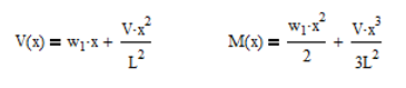
The distributed load that constantly increases to w (5 lb/in) will follow the equation (I looked it up in a table):
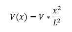
Where V is the shear force at the end of the beam and is equal to:
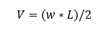
In our case, V is 810 lb. We now need to integrate these two components which we will do mathematically. This is easy calculus so don’t get worried. Integrating polynomials is simple because you just need to add an exponent to x and then divide the term by that new exponent. This leads to the equations:
Ok, so you can see why, I recommend sticking to the tables. So from our equations, we find that the moment at 180 in is 28,416 in lb. Now you may have just said, “Corey, I calculated 47,400 in-lb. What happened?” Good question. The answer is simple, we marked our distances starting from the vertical moving left, but then we started counting our x dimension from the end of the pole moving right. This greatly simplifies the calculation, but it can cause some confusion so be on the lookout for changes in coordinate systems. Luckily, if we didn’t catch this, we would end up with a stronger pole, but that is not always the case.
Our second equation yields a moment of 192,456 in lb. at the vertical member. When we add these to the moment from the point load we get 100,416 in lb. at 180 inches and 475,656 in lb. at the vertical member. You can see here that the weight of the beam was a significant component in the loads on the beam. I’m glad we included it. Off to the next step.
4. Calculate the section properties
The section properties are the mechanical properties of any section. To properly select a cross section of interest first do a visual inspection and see if there are locations that pop out. I chose two locations on the traffic light pole. The most obvious location was where it attaches to the vertical member. I chose it because I knew the moment would be highest here. The other was at the third light from the end (180 in), because it had some moment, but the cross section looked weaker there.
When calculating your cross section, be sure to cut perpendicular to the section. The traffic pole has a curve to it as it reaches the vertical member so we don’t want to cut our section vertically, but at an angle perpendicular to the tube axis. If we don’t cut normal to the axis, we end of getting a larger cross section than what is actually there. In this case a tube would become an oval with larger height and thicker top and bottom material. Not a good thing to do.
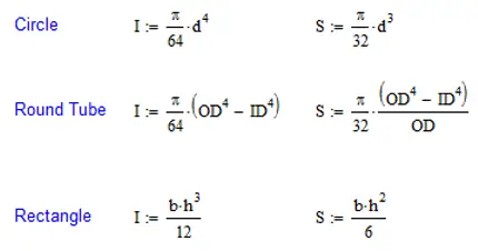
There are two components of the section that are important. The first is the distance from the centroid to the outer fiber of the material. If the beam is horizontal, it will be to the top or bottom of the section. This distance is referred to as ‘c’ and has the units of length. The other component is the area moment of inertia or the section’s resistance to bending. The larger the section, the more resistance there is to bending. This is specified as ‘I’ and has the units of length^4. The area moment of inertia is a double integral of the area from the centroid. It is far more calculus than I am willing to do so you can look in the back of many textbooks or do a quick web search. The most common shapes I’ll list here and they are easy to remember. (I didn’t even have to look them up for this). The section modulus, S, is simple area moment of inertia divided by the distance to the outer fiber (I/c). This is one thing that I will never forget due to the late Dr. Tommie Thompson. He put this on a test having never mentioned it in class and there only being a short mention of it in the textbook. Naturally, my test grade went down by almost a full letter due to this small oversight.
One thing that I really want to drive home on this is that the area moment of inertia really drives deflection. The larger the value of I, the stiffer the section is. However, the section modulus, S, drives the strength of a beam. It is sometimes difficult to explain how adding material can weaken a structure. I had a client that was insistent that adding a bar to the top of a rectangular tube would make his apparatus better (meaning stronger). And he was right in one way and wrong in another. The bar definitely made the beam stiffer, but at the same time, it was weakened because it took material from the outer fiber and place it closer to the centroid. I can’t remember the exact details, but the beam was similar to what is shown below.
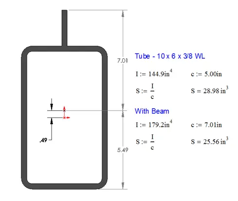
The ratio of the area moment of inertias shows an increase of stiffness around 24%, but the overall strength of the section is reduced by almost 12%. My first caution is to make sure that you don’t inadvertently do something like this to your structure by adding a gusset. My second caution is to make sure that you carefully choose your materials. If the tube is 46 ksi yield, adding a gusset of matching strength is bad enough, but if that gusset is A36 material, that makes it even worse.
In summary, you need a well-defined cross section and know the area moment of inertia and the distance to the outer fiber or the section modulus before you can continue.
5. Calculate the stress.
Most of us remember that there is a neutral axis when bending loads exist. This is a line that goes through the centroid of the section. As we go from the centroid out, our stress increases linearly despite any changes in cross section. I mention this because there may need to be several locations where stress needs to be checked. A good example of this the tube with the plate added to it above. If the plate is 100 ksi yield and the tube 46 ksi yield, I would want to check the stress at the very top and very bottom of the section.
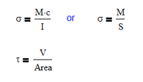
From here, calculating the stress is a walk in the park. The governing equations for calculating normal and shear stress in a beam are:
Since we already know the moment, M, and the section properties, we can just plug those values in and go. For long beams, shear stress is usually a very minimal contribution to the overall stress. But, it is usually a larger component on shorter beams. This is why it can be ignored in most cases.
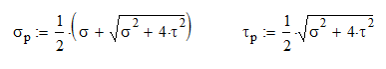
Once we have our shear and normal stresses, we can combine them using Mohr’s Circle. I’ll be honest with you, Mohr’s circle is presented in a way that is way overcomplicated and I have tried to simplify it. Please watch my video on Mohr’s circle for a simplified approach. The resulting governing equations are:
These stresses can then be compared to the yield stress. The normal stress is directly comparable, but the shear stress need to be modified by a factor of 0.577 to account for a material’s shear strength being roughly half its yield strength. (It’s all explained in the video, you should watch it)
Going back to our examples, we wanted to look at the stress at 180 in from the vertical and at the vertical. Here is how I would calculate the stress and compare it to our yield strength (assumed to be 70 ksi)
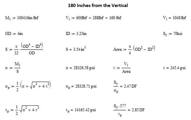
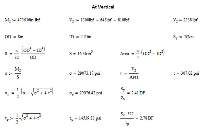
You might have guessed that I randomly selected a tube cross section, and I did. There is no significance to the design factor in this example. I am unaware of any structural design criteria for traffic light poles. I’m sure whatever standard there is it contains requirements for wind, snow and seismic loadings as well. Had we been doing a full design of this beam, we would have wanted to include all of these loadings and considered loadings in multiple planes. All of this is a subject for another article.
Design Factors (A quick word)
Design Factors, also known as Safety Factors or Margin, are cushioning between the actual loading and the calculated loadings. Often you will find a specified factor listed in the specific standard that is for your particular application. Often times, these are based on a 2:1 design factor for a ductile material. The reason for this is that 2:1 is usually under the fatigue endurance limit for the most common steels (under 100 ksi yield strength). If this design factor is adhered to, issues with fatigue rarely show up and if they do, it is usually because of a large stress concentration or unintended loading.
Some standards would specify a base design factor and then add on factors for stress concentrations and dynamic loadings. These numbers would all be multiplied together to get the design factor used in hand calculations like we just did. However, with the advent of Finite Element Analysis (FEA) in the last twenty years, we can simulate stress concentrations and some dynamic loadings. As a result, more and more standards are being rewritten to remove these extra factors.
There are other standards, some in the oil and gas industry, where the maximum load is unknown so a very low design factor is used on a very high theoretical load.
Other things to consider are loads produced by wind, rain, snow etc. Excessive dynamic loads can be a significant stress component for trailers and off road equipment.
If there isn’t any specific design standard here is my general rule of thumb for design factors:
- General design 3 : 1
- Non-working load cases 1.5 : 1
- Trailers or off road devices 4 – 6 : 1
Conclusion
I remember in school thinking how difficult it was to calculate the stress on a beams and how time consuming it was. I now laugh at those days, because it seems so simple to me now. Following these steps allows you to focus on each part of the beam and how that effects the stress. If you do it often enough, it will become second nature very soon.