

I recently stayed at a very nice hotel and out at the pool there were some plastic rocking chairs. I sat in one and rocked for a few minutes and noticed something odd. In addition to the chair rocking, there was a vibration where one side of the chair was leading the other.

The cause of this was obvious; the floor was uneven. This sparked my interest because I had never noticed this in any other, mainly wooden, rocking chair. Not being content, I had my wife sit in the rocking chair next to me and she noticed the vibration as well.
Even on vacation, I cannot turn off my mind so I flipped the chair over and immediately noticed what caused the issue. The sections that made up the chair were open sections in the shape of a U and would deflect much more than an equivalent wooden rocker when in torsion. That extra deflection, allowed the vibration I noticed to occur. In this article, I will discuss multiple ways analyze and improve torsional resistance in structures so that you will design a better rocking chair.
In order to design a better section for torsional deflection consider using closed sections like bars or tubes; avoid plates and structural shapes. You can also box in open sections, thicken walls and apply bracing.

1. Open vs Closed Sections
One great challenge of engineering is designing structures for torsional loading. This can be an issue for two reasons: first, calculating the stress in open sections can be rather difficult. Second, the deflection of a section can be excessive and ambiguous to calculate.
Let’s examine why designing for torsional loads are much harder than bending. In the, I beam shown, tension and compressive stresses flow through the top and bottom members. The deflection will be very predictable since it is governed by the equation:

Where M is the moment applied, E is the Young’s modulus, I is the Area moment of inertia and v’’ is the second derivative of the deflection. Using this equation, you can use your calculus skills to integrate and setup your boundary conditions etc. I prefer to look these up in a table like everyone else. My reference of preference is Blodgett’s Design of Welded Structures.
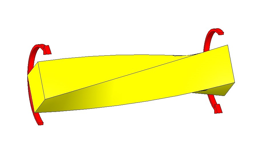
Now, if we take the same I-beam and apply a torsional load to it, logically we would expect it to have a large amount of deflection. But why? The reason for this is that there is nowhere for the torsional stress to flow. In bending, the web of the beam takes the shear load in between them. If you remember the first few days of your Mechanics of Materials class, you will recall that shear stress is maximum at 45° from the longitudinal axis where it essentially becomes a normal stress.
Consider applying torsional stress to the ideal section, a tube. This is because the torsional stress has some where to flow. Imagine taking a tube and cutting it at a 45° angle from its axis. (Think of a candy cane stripe.) Now flatten it out. What do you have? It is a flat bar. Since shear stress is normal stress offset by 45°, normal stress flows freely through the flat bar.
With torsional loading, there are two types of sections, open and closed. An I-beam is an example of an open section and the tube is a closed section. Obviously there can be combinations and modified versions of both. Closed sections are preferable for torsional loading because there is a very clear path for the shear stress to flow in. The generic closed section torsional formula is based on the “average enclosed area.” The larger the enclosed area, the better the torsional resistance. There are trade-offs with using a closed section. In the table below, three sections with equal areas are compared. You can see that you can shape the material to be good in bending or torsion, but you will have to compromise to get one that is good in both. An I-beam is great in bending and conversely, the round tube is great in torsion.

You can also see that the rectangular tube is a decent compromise and is readily available. From quick inspection, you can see that material had to be taken from the flanges of the W beam to form a second vertical that creates the wonderful closed section.
When you can use a closed section, do so. But what happens when you just have to use an open section. Two very important questions come to mind. How much will it twist? How do I make this section better?
Good news! Both can be answered.
2. Box in Portions of Open Sections
For the former question, I wanted to point out the excellent work of Omer Blodgett in his book, “Design of Weldments” put out by Lincoln Electric (Section 3.6). If you do not own a copy of this, get one. It is a priceless tool every mechanical engineer should have. In the torsion section of the book, Blodgett describes how torsional resistance can be calculated using some formulas. He then correlates the calculated deflections with real deflections. For most open sections you find, you can use his torsional resistance method to calculate the stiffness of your section by combining smaller components that he provides information on. For example, Blodgett describes an I-beam as three flat plates. From these equations, we can easily estimate the twist and see what changes will make it better (or worse). Since this is an empirical principle, it is not 100% accurate, but will give a reasonable representation.
The latter question can be answered by understanding that closed sections don’t have to be closed the entire way. Let me explain by making a parallel to a section in bending. Going back to I-beam example. If I put a small hole (Figure 1) in the web of the beam, the shear stress will simply flow around it. It makes a stress concentration. If I make the hole a slot it (Figure 2), there may be more of a disruption in the flow, but the beams is still going to work well in bending. Now, if I make the slot longer (Figure 3), at some slot length, the whole I beam section will stop functioning as a unit. This will result in bending stresses in the flanges (not just tension or compression) and the section is no longer capable of working as intended.

Figure 1

Figure 2

3. Apply Bracing to Open Sections
The same is true in torsion, having a closed section for part of the way will improve the rigidity of the beam. Let’s say that our I-beam is cantilevered with an offset vertical load on the opposite end. On the mounted end, it is boxed in for the first 10%. The boxed end stiffens the entire length (not as much as a fully boxed section) because it forces the flanges to bend upon their strong axis. Since torsion flows in a constant direction, the flanges will bend in opposite directions. In figure 4, you can imagine a torsional load bending the top flange away from us and the bottom flange towards us. Figures 5 and 6 show alternate methods of boxing in a partial section.

Figure 4 – Boxed in end section improves torsional rigidity by forcing the flanges to bend as well as twist.

Figure 5

Figure 6
What I want you to understand is this: a section doesn’t have to be perfect or uniform the entire length to do what it needs to. A slot in an I-Beam is acceptable for bending and a semi-boxed in section used in torsion can work as well. I do want to point out that some of these methods may create rather larger stress concentrations where the sections change. Be aware of this and be sure to taper plates to alleviate large stress concentrations.
4. Increasing the Thickness
As a last resort, increasing the thickness of a plate will increase torsional stiffness. This comes at a large weight penalty so use this sparingly. Please note that the largest shear stress on a plate will occur at the center of the longest side. You may be able to add more material by welding a thinner plate in this location. This will minimize some of the added weight.
Conclusion
Designing for torsion can be daunting, but with practice, your mind will start to breakdown the sections. It will first happen by spotting open and closed sections. Then it will break open sections into calculable components. Pretty soon, you will love the creativity you can use in open section design. Remember to ask yourself: How does the stress flow at 45°. Can I enclose this section? How about part of it? It isn’t as tough as it seems once you know what to look for.
Now go design your better rocking chair!
Very Interesting!