In this one, we’re going to talk about a few subjects. The first one being fatigue and wear. Now fatigue is more of a problem that usually evidence itself by a tooth breaking off. And a lot of times that’s just due to high load. So, the first thing you can do is get your diameters up.
And what that really does is it sometimes eliminates the amount of torque that needs to be produced and lowers your tangential force. The other thing it does is if you go to a bigger number of gears, it actually raises your Lewis form factor. We’re still working under this equation. The other things we can do are we can raise our allowable stress. That could be done just by using a stronger material or possibly hardening that material.
There is a cutoff as to how much that will help you in fatigue. Obviously, if you’re getting up to 180, 200 KSI on your gear teeth, you may want to change and try a different design. We can increase our rack width or just our gear width sorry or we could decrease our pitch diameter and with all these things there are trade-offs with power transmission and just the size to put all these things in maybe you find that gears just aren’t the right method of transmitting that power. Maybe something, a V-belt or a chain and sprocket system would be better.
Who knows? So, one thing you can do with gears to make sure they don’t have premature wear is to make sure that they don’t mess with the same teeth every time they go through. Alright, so if we look at this, this gear has 24 teeth, and this one has 40 teeth. Alright, I could divide both by 8, so this would be 3 and 5. So for every 5 revolutions, it’s going to line up perfectly again.
With the teeth on this one which will have completed three revolutions and that’s not terrible but if I had let’s just say this was 24 and 48 that means every two revolutions I’m hitting on the same teeth and that’s you know that’s getting down there but if I had 23 and 48 wow that’s quite a few revolutions away that they’re that they’ll mesh again and that just helps us to keep the pinion teeth wearing because generally speaking the smaller gear is going to wear faster than the bigger gear will all right so we want to make sure that we look into that when we’re designing our system and just see you know can I just make this of a weird number of teeth
The second thing I want to talk about is material. So, your materials are an important thing. You basically have three categories. You’ve got plastics, you’ve got brass and its subsidiaries, and then you’ve got steel. And you’ll see gears made out of different things, but we’ll just kind of go through them and highlight the good and bad things of them.
We won’t get very deep into this. There’s a lot of research that can be done here. So plastics are more for precision, low torque things. Lego gears are made of plastic because they can withstand High speeds, fairly well. They don’t shave on each other much.
Basically, they’re going to last as long as you’re not transmitting a lot of power. As you get down to the harder materials, brass, probably the first chance that you’re going to actually be able to transmit some sort of power. The wear is pretty good on that, but as with metal on metal, you’re going to have more heat building up, so you’re going to need something to remove that heat. Lubrication is a great way to, one, prevent the heat from starting, and two, just remove the heat immediately. It’ll flow right into the fluid and be okay.
And then steel, steel you can get that really hard. You can transfer a lot of force through gears and that’s probably the number one choice of bigger gears is steel. Obviously, they cost more than plastic gears but they’ll last a lot longer under the loads consuming. One of the things that I haven’t touched on is with these is speed. You know, plastic gear, plastic is much, much lighter than steel, probably about fourth to an eighth of the weight.
So, you’re not going to have a bunch of mass trying to fling itself. You don’t have to worry about out of balance as much. So, if you’re using it at high speed, plastic is going to be a much better material than steel will. Alright, well that’s all I wanted to focus on materials. So, the last thing I want to talk about in this video is run out.
Run out is the eccentricity of the gear to the shaft. So, there’s three different kinds. There’s axial, angular, and radial. Alright, so radial is very simply put, I have a shaft and then I have a clear you know distance that it is out of round all right and that’s you know shown right here as it goes around it’s going to flop around like that that’s radial run out axial run out is if I have a gear on a shaft and I put a an indicator right on the surface
and I watch the dials I go around you know what is it what is it moving and you know probably have a tolerance of what is acceptable if you’re doing it on a large crane rotation bearing quarter inch may not hurt you but if you’re doing some something precise like a clock or a watch or something like that ten thousands maybe way too much And then angularity this would be you know how the how the gear is pressed on the shaft You know you want to find out essentially What is this angle right here?
And that’s going to tell you something that kind of tied closely with the angular or the axial road run out so Just so you’re aware of those things and you can keep an eye on them. Now, there’s two types of gears. There are normal gears that you’ll buy and then you can buy precision gears.
And these things, somebody spent the time, and you will spend the money if you use them to get these where… All these runouts are very small. The teeth are almost exactly identical. They’ve probably even been put on a CMM machine, a coordinate measuring machine. Well, they will go through and trace the profiles at various depths through the gear tooth.
it’s there you can buy it and it’s expensive but these things will be minimized however for a lot of cases probably just don’t need it the last thing we want to talk about here is backlash is something that all gears have and we want to try to minimize it in certain conditions it’s basically a sloppiness between the two gears so we run a balance between The two gears meshing on this side and having a gap over here, you can see this gap right here. If we have a crane pivot where it’s rotating side to side, we probably want to keep that fairly tight.
because we don’t want the crane going jerk, jerk, jerk, jerk, and then it’s got some momentum every time it hits each side of the teeth just it’s going to wear it might even fatigue a tooth off if we were to do that you know several hundred times so you want to get that fairly tight just so it feels snug and as I mentioned earlier you basically want to go in and be able to adjust that dimension. My favorite way to adjust these is to take one of them, usually the pinion, and make an eccentric hole for it.
So, I’d have my hole directly on top of that and then I’d have Another hole. No, pretend those are round. I’m sorry. My freehand drawing is not that good. But you can clearly see that, let’s just say, the center of this hole, the inner hole, is there, and the center of the outer hole is there.
And maybe, I don’t know, depending on your application, that’s 1 16th to 1 8th of an inch off-center. Whoops. 1 8th, not 18th. And you can… Adjust that as needed by rotating this around and they go closer together or further apart. Now what you’ll need is some way to lock them in place.
There’s some way to do it. You can kind of put almost teeth on this and then have some sort of plate, lock that in, or something like that. You’ll have to get a little creative there. I’ve got some ideas, but they’re proprietary, so I’m not going to share those. So that’s just one way to do it.
You can just clamp them together. clamp this to something else and just allow friction to account for that. That might loosen up over time. You probably want more of a positive engagement. So, the way you would measure that is you would take whichever gear remains steady.
Let’s just say it’s this one. This is the pinion gear that’s driving this gear. What we want to do is get in as close as we can and we’re going to mount a dial gauge here so that’s not a good so what we want to do is we want to come up on this tooth and get as perpendicular as we can and put a dial gauge here and have it mounted back to this gear whatever holds this gear that whole mechanism
and then we want to just rotate it back and forth until we get whatever amount of backlash we’re okay with but it basically just measures how much change is going to happen when we when we rock this thing back and forth generally you want to see you know five to ten thousandths or something of that nature if you get tighter than that you’re going to start to buying this up right here also a lot of gear manufacturers know that their gears aren’t perfect and they will actually indicate to you usually by painting on there which teeth are the highest or the most oversized the target so that way you can mesh those ones and then put your dial indicator on that and do that.
So, if you don’t know which ones are the high ones, you may have to do this several times. Okay, well thank you for watching this episode. Be sure to join us on the next one.
How to Easily Move Objects While Keeping Them Level
There are many times in my design career that I needed to
translate an object without rotating.
Lifting an object on a table is a great example of this. At an airport we may see a baggage loader
using a scissor lift to load and unload your personal items. In most cases, we want to maintain level with
the ground, but often we just need to keep the same angle. I once designed a holder for a seam welding
robot that needed to keep the tip at a specific angle relative to the
part. It was not horizontal.
There are five
main ways to move items without rotation.
They are:
Parallel Links
Chain and Sprocket Leveling
Scissor Lifts
Hydraulic Leveling
Electronic Leveling
All of these have their strengths and weaknesses and we will
discuss them. Let’s explore each one
more.
Parallel Links
Parallel linkage is probably the most recognizable method of keeping level. Two equal length parallel links are hinged to fixed pivot points. The line drawn between the two pivot points is the line we will remain parallel with as we rotate the links. Please note that the links do not have to be straight. They are two force members (like a rope in tension) so if they are not straight, you will have additional moments to calculate. It is also self-evident that you cannot get continuous rotation with this system because the links will interfere with each other.
There are two main things to consider about
designing a system of parallel links. They are load magnitude and load placement.
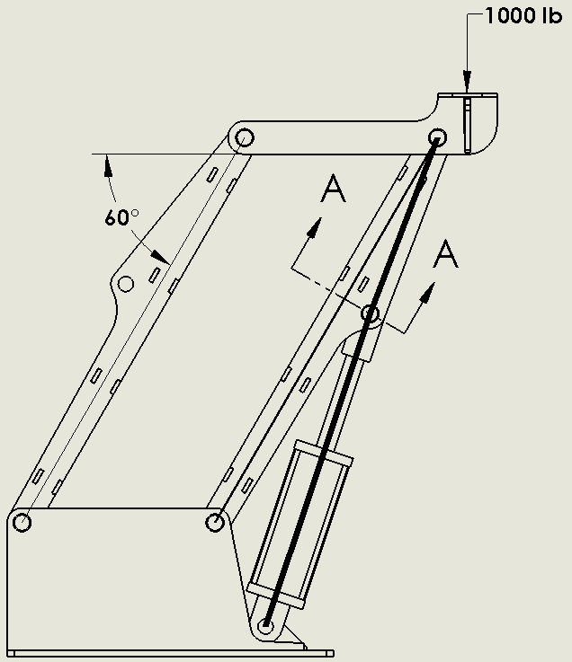
The placement of the load has no effect on how hard it is (for the cylinder) to lift up the load. It seems backwards, but the cylinder is only responsible for lifting the magnitude of the load. The placement of the load is managed by altering the force in the links. This is why you often see small cylinders lifting large loads. Let’s dive deeper into the math.
Figure 1
So, I’m going to prove to you that the placement of the load does effect something, but it doesn’t affect our cylinder load. For my first case, I’m going to put one hundred pounds right over the pin, and calculate the tension in the member left link. Doing the statics you need to sum the forces at the pin where the load is applied. The moment is the load (100 lb) times its moment arm (0 in) divided by the distance between the bars (11.26 in). Anything multiplied by zero is still zero, so there’s no force in that link. It’s kind of along for the ride and it’s just making sure that the bar maintains level.
I will now move my load out 20 inches and
recalculate. I’ve now got a moment of
100 pounds times 20 inches or 2,000 in-lb.
If I divide that by 11.26 in, my force will be 178 lb. So, I’ve increased the link load significantly
by moving it out 20 inches. The tension
member is very easy to calculate, but the compression member is a little more
complicated because of the cylinder. The statics on the compression link is a
little out of the subject so I won’t cover it in this article. It isn’t too difficult to calculate anyway.
Now let’s move onto the calculation of the
cylinder force. It is largely a function
of what the moment is at Section A-A. This
moment is equal to the distance (12.56 in) times the load (100 lb) times the
angle between the two (60°) which equals 628 in-lb. Because of the pivot point at the end of the
link, there will never be an increase if the load doesn’t increase. To say it another way, the shear load in the
top member is always 100 lb, but the moment load changes. We are only concerned with the shear load in
this calculation. (Please note that the
moment at A-A will change as the angle changes, so be careful). With linkage, you can get away with a relatively
small cylinder to lift heavy loads because of this principle.
Load
placement is critical for designing a system of parallel links. You can
actually double the loads in a link if you are not careful. In the example above, I may have a load that
centers on the pin and through its travels, the load may actually slide to the
left or right. If we were using this to
load baggage onto an airplane, we would have loads that shifted from roughly
the center to the edge of the structure.
I mention this because we always want to have the cylinder interface
with the compression link and we always want the compression link to stay in
compression.
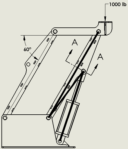
The reason that it matters is simple statics. Looking at Figure 2, the stress flow is clear. Our cylinder is in compression (if I remove it, the structure will fall to the right). As long as the link is in compression, the stress will flow nicely as shown with the thick line. However, not all of this load will flow through the cylinder (especially as the angle changes) and a small amount will be directed to the link. The point is that we will have a smooth stress flow throughout the link and cylinder.
Figure 2
If I move the load further left of the left link, I will change the direction of force in the right link. The link with the cylinder is now in tension. (Note that if the load is between the links, both will be in compression). Now the cylinder is still in compression as it tries to hold the load up. If we look at the modified stress flow in Figure 3, we see that the primary stress flow is between the two pivoting pins and it is in tension. However, the compressive load of the cylinder needs somewhere to go. It wants to go up to the top pivot, but there are no forces to balance with. It then needs to make a U-turn (it’s quite awful) and flow back to the lower pivot. This stress from the lower pivot to the cylinder mount is a tensile stress and will add to the tensile stress of the link. The result of the link being in tension is an amplification in stress. Also note that stresses don’t like making U-turns. By definition, it is a large stress concentration and will have you pulling out your hair in FEA (yup, been there). As a rule of thumb, always try to have your loads biased so that the member of the cylinder is in compression so that your links can be small and effective. In the rare case where I couldn’t prevent the reversing of loads, I was usually able to minimize the effects by limiting the offset distance and the magnitude of the load.
Figure 3
Parallel links are powerful tools and are used in many different types of machines. The benefits of using small cylinders to lift loads are self-evident and allow the lifting of heavy objects at longer distances.
Chain and Sprocket Leveling
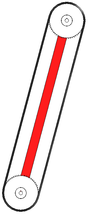
One of the limitations of parallel links is that you cannot do continuous motion. In fact, the practical limits of a parallel linkage system are usually below 125°. Of course, there are always exceptions. Now if articulation is a limitation that you need to have eliminated, going with the chain and sprocket form of leveling is a better idea. A chain and sprocket leveling system or ‘chain leveling’ works by having a bar or link of a fixed length and mount a sprocket on each end. The sprockets must have the same number of teeth to work properly. A chain then goes around the two sprockets. The sprocket that is mounted at the pivot is usually fixed. So, as you rotate the link around, the chain winds on one sprocket and unwinds on the same amount on the other sprocket. The result is the free end sprocket staying in the same rotational position throughout its motion. Also, if you setup the geometry so that the components don’t interfere, you can go 360 degrees around this if you need to and you could do it continuously – not just single rotation!
As you can imagine, backlash and chain slack is important so having a method to tension the chain is needed. This can be done by adding a chain tensioner or even making the link adjustable.
Chain leveling is also a great choice if you need to electrically insulate the ends. By changing from chain (and link) to a non-conductive material it is possible to have each end of the device at different electrical potentials. When you do that, you lose the ability for continuous rotation.
When calculating the loads on a chain and sprocket system, we run into a few issues calculating the loads. We immediately notice that the chain will act as a couple (two parallel forces in the opposite direction but equal in magnitude and separated by a perpendicular distance [obviously]). However, chain doesn’t handle compressive loads and will slack under any compressive load. Once the chain goes slack, we now have to create the couple in the tension side of the chain and the link.
Let’s work a small example. A chain leveling system will have a sprocket 20 inches in diameter and a preload of 1000 lb on the chain. A moment of 30,000 in lb is applied and then removed.
To solve this we must load the system in two steps. Step 1 is to unload the chain on one side until the applied moment is equal to the chain pretension. At this point the tension side will have the same load as the pretension value, but the other side will be completely slack. It is important to note that there will be no increase in load on the tension side at this time. We are just unloading the slack side. In our example this is a moment of (20 in)*(1000 lb) = 20,000 in lb.
In Step 2, we have to load the remaining 10,000 in-lb by using the center link as the distance for our couple which actuates at half the sprocket diameter. So 10,000 in-lb / (20 in / 2) = 1,000 lb. When we add this to the preload, we find that the tension in the chain will increase from 1,000 lb to 2,000 lb as the moment is added.
In practice, we want to minimize the load induced in the Step 2 calculation by having a good amount of preload in the chain. This will prevent fatigue from being a failure mode.
So one neat thing with chain leveling is that you can route the chain however you want to, as long as the sprockets on the ends are the same size. You can route the chain over as many other sprockets as you need to. You can even have the two chains running right next to each other! I’ve seen cases where a large sprocket is needed, but it will not fit into the tube. The solution was to have the chain run across plastic wear pads and ‘dog bone’ into a smaller tube.
One benefit of chain leveling over parallel links is that we can rotate the bottom sprocket and make the top one rotate as well. This is useful for periodic cleaning; when the bottom sprocket is rotated, a once horizontal surface at the top sprocket is now vertical and debris or collected water can easily be removed.
There are two other drawbacks of chain leveling systems. The first is there is a practical limit to the moment that can be handled. This is limited by the size of the sprocket and the size of the chain. The other limitation is the same as parallel linkage. The translation is at a fixed radius and the motion is limited to polar coordinates. This means that there is no linear motion, just angular.
If you need linear motion in one direction, scissor lifts are your “go to.” The structure is named after the well known cutting tool and they will cut or at least smash your hand if you get too close. They are the predominant method of lifting materials in a linear fashion to heights far exceeding the collapsed height.
Scissor lifts seem pretty obvious as to how they work, but they are more complicated then they appear. First of all, calculating the forces on the system is extremely complicated. In fact, some scissor lifts are statically indeterminate based on how the cylinders attach. As an approach, each link will need to have a separate Free Body Diagram and many sets of equations are needed to find all the resultant forces.
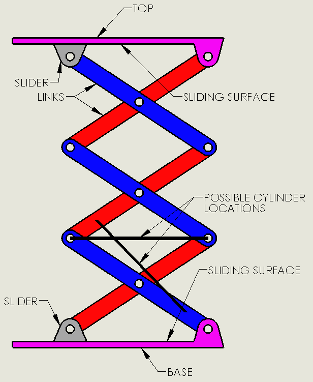
A scissor link will have five main components: links, a base with sliding surface, a top with sliding surface, sliders and a cylinder. Two cylinder locations are shown but more are possible. The angled one is the most popular because it allows the cylinder to be in compression thus creating more force.
Some things to consider in a scissor design is how the top member is loaded. If the sliders ever get into tension, there will not only be slack in the system, but you will need to have a way to retain the sliders to the top and base components. One way to minimize or eliminate that is to bias the loads so that they are closer to the slider reaction point than the pivot points. You will definitely want a way for the slider to remain connected to the top or base even if it is only able to take incidental upward loads.
Another thing to watch for is chatter. Chatter will often come from the sliding surface being too far from where the slider pivots. Minimizing the distance or maximizing the slider length can help. Often times, the use of cam rollers for the slider is a great design.
One great thing about scissor lifts is how readily available they are! You can easily find versions powered by electric, pneumatic, spring and hydraulic actuation.
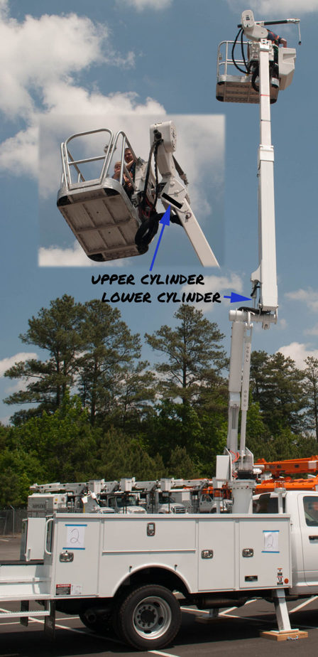
Hydraulic Leveling
Hydraulic leveling is the most complicated mechanical method of keeping a surface level because there are many components that need to be factored in. The traditional use is for platform leveling on a man lift. At the platform, there would be an upper hydraulic cylinder between the platform and the boom. This cylinder is driven by a similar lower cylinder between the boom and the riser or knuckle. It is important to note that the lower cylinder does not raise and lower the boom, it is there to tell the upper cylinder what to do.
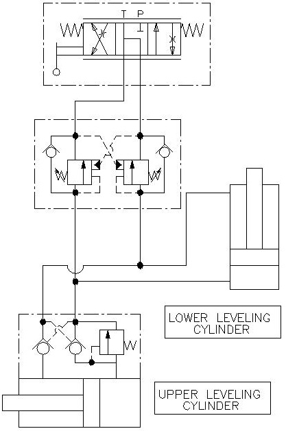
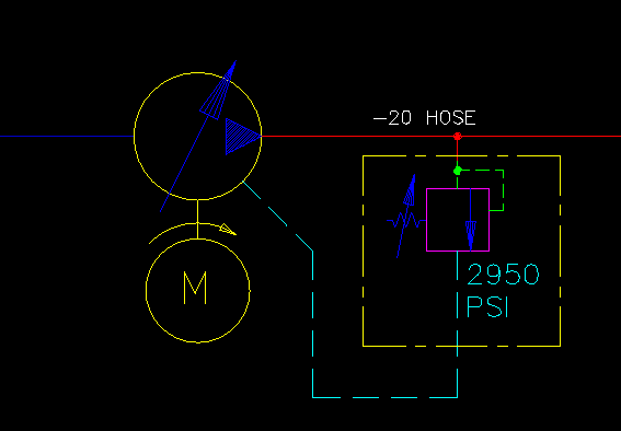
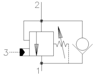
How it works: Looking at the schematic below, we can see that there are five main components: The upper and lower cylinder, a load holding valve on the upper cylinder, a dual counterbalance valve and a directional control valve. The directional control valve and dual counterbalance valve are for retiming, so we will ignore them until later in the article.
We will illustrate how the system works by going through a cycle. We will start by having a boom in the lowered position so that the lower cylinder is retracted and the upper cylinder is extended. When the boom is raised, it will force the lower cylinder to extend. Oil in the rod section will be forced to leave and travel into the upper cylinder where it will build up pressure and pilot open the counterbalance valve and enter in the rod section there. Oil from the bore section of the upper cylinder will be forced out and travel to the lower section. When we lower the boom, the opposite happens.
To design good hydraulic leveling, you will want to consider six factors:
Cylinder Size: The first thing that you will want to do when designing hydraulic leveling is select cylinders with the same geometry. The bore and rod size and the stroke length must be equal. If there is any difference, you are not going to get good results.
Extra Stroke: It is recommended that you allow for at least ¼” of extra stroke on each end lower cylinder. You don’t want to get into a situation where the boom lift cylinder is not quite all the way extended, but the lower cylinder is extended already. As you can imagine, the boom lift cylinder is much more powerful and it is going to pull the lower cylinder apart. Very bad things will happen. You also want extra stroke so that variations in fabrication don’t stack up and cause problems.
Load Holding: Hoses occasionally break, so you also want to add on load holding right on the upper cylinder to prevent any unintended motion of the platform. Counterbalance valves with 3:1 or 4.5:1 ratio should do well in this application. Be sure to set them at least 15% higher than the system pressure.
Limit Pressure and Fluid Velocity: In order to keep these cylinders timed we need to limit the pressure and fluid velocity. First off, you are going to want to look at the velocity of oil that’s exiting the cylinders and keep it to a velocity of less than 10 feet per second. This would be the same as you would have for a standard hydraulic return line. The reason for this is that you don’t want to have large pressure drops just to move the fluid back and forth between the cylinders. You want the fluid to do the work of maintaining level and not just trying to get out of a counterbalance fast enough. Increase your hose size to remedy this. Keeping your working pressures low is also important. You will want to be working with pressures about 2/3 of the system pressure. For a 3000 psi system, we will want to have our cylinder operate at 2000 psi. The reason for this is we don’t want sudden pressure spikes causing the counterbalance valves to open and level to change unintentionally. As a result, you will need to increase the cylinder bore and stroke length on both cylinders.
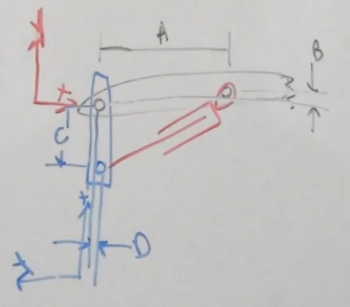
Account for Deflection: This is probably the most overlooked criteria because it is not obvious. In an ideal world, designing the cylinder geometry exactly the same on both ends will work perfectly. Making geometry the same would require that the dimensions (A, B, C, and D) in the picture here are the same for both the upper and lower cylinders. Keep in mind that the rotation of these components can be changed. However, this is the real world and booms will deflect. When the boom is loaded in a horizontal position it may deflect 5° but when I have the boom near vertical, it may only deflect 0.5°. If we don’t account for that, the platform will not track correctly and be out of level. To account for this, the cylinder geometry must cause the platform to rotate 4.5° more than the boom rotates. This causes the cylinder geometry to be slightly different on each end.
Manual adjustment: Hydraulic leveling isn’t perfect and from time to time, you will need to adjust the platform level. In the schematic above, we will need to add a directional control valve for two reasons. The first is obvious; to occasionally adjust the platform level. Second, we need a way to prime the cylinders and hoses. Air is not a friend in any hydraulic system, so getting oil in and air out is important. Closed systems like this one are difficult to get the air out so I recommend cycling the platform fully when the boom is up and down twice.
Direct use of a direction control valve with closed center work ports presents two problems. First, if there is a pressure spike, flow back to the tank is blocked so the system will need to absorb the excess pressure. The second reason is that while the schematic shows the ports being blocked, in reality the valve does have small amounts of leakage. This is due to the valve spool having a small amount of clearance in the hole that was bored. While this amount of fluid is small, it is usually measured in drops per minute. Leaving a unit setup overnight might yield a dramatic change in platform angle.
Placing a dual counterbalance valve in between the directional control valve and cylinder circuit solves both of these problems. It will make a no-leak seal on the cylinders but also allows for relief from pressure spikes as well as thermal induced pressures. These counterbalance valves are purely for load holding so using a higher ratio valve is appropriate. I recommend a 10:1 valve set at 15% higher than the system pressure.
Hydraulic Leveling
Type 2
There is another type of hydraulic leveling where a level switch activates a directional control valve when the platform is more than a few degrees out of level. This type of leveling is simple, but very jerky and has a ratcheting effect. I mention it only to round out the picture because this type of control has been replaced with electronic controls.
Electronic Controls
Electronic control systems for leveling systems are where the industry is going. An electronic control system will monitor an analog sensor or encoder based level indicator and make adjustments as needed. Using a PID or equivalent control system, hydraulic cylinders are actuated by proportional directional control valves. Using proportional valves allows for near seamless leveling control and includes the possibility for controlled acceleration and deceleration. Electronic control systems can also control leveling in two directions.
Conclusion
Lifting objects is an essential part of engineering. Keeping them level throughout the lift is a welcomed challenge but can be stressful. After reading this article you should be able to select several practical methods of lifting without rotating. You should also be able to take initial steps to designing each type of system.
Reading a hydraulic schematic for the first time is a
daunting and confusing thing. There are
so many symbols to identify and lines to keep track of. I hope to impart to you a systematic approach
to reading a hydraulic schematic.
The basic steps to
reading a hydraulic schematic are:
Identifying line types
Identify if lines cross with or without connecting
Identify the components
Identify the flow path at a de-energized state
Determine what happens as each valve is moved
Activate multiple valves at a time to see if there are unintentional consequences.
So, the good thing about this is that while we are using hydraulics, a lot of this is directly related to pneumatics. Pneumatics will have a few extra components that we don’t use in hydraulics such as oilers, air dryers and Venturi Vacuums, but they are similar.
Let’s get started.
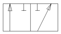
1. Identifying the line types
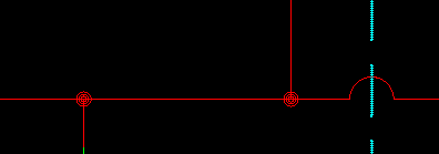
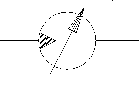
In a hydraulic schematic, each line type has a unique meaning. In addition, colors can be added to indicate purpose of the line. In the figure below, all of the basic line types are shown. The basic line is a solid line that represents a working pressure hose or tube. The red line indicates pressure and the blue line indicates a low-pressure return line. In this case, it is a suction line for the pump. The teal and green dashed lines are called pilot lines or drain lines depending on their purpose. Both lines shown here are pilot lines. A pilot line is a high-pressure line with low flow (1/4 gpm). A drain line is the opposite, a low-pressure line with higher flow. Finally, the yellow center line around some symbols is an enclosure line or bounding box. The purpose of this line is to show that all the components within are contained in one valve block or manifold. The purpose of this is to simplify real-world identification.
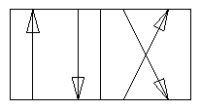
2. Identify if lines cross with or without
connecting
There is a little controversy with this one. In the early days, if two lines crossed, they were connected. If you didn’t want the lines connected, you would draw a hump across one line adding some drama to the schematic. Well, as more and more people heeded to the advice of the Black Eyed Peas saying the, “you don’t need no drama, drama, no, no drama, drama” the standards were changed. Now, you will need a dot to indicate crossed lines that are joined. If there is no dot, there is no connection. Who knew that the Black Eyed Peas were actually singing about hydraulic schematics? Ok, so the song obviously doesn’t have anything to do with hydraulics. In all honesty, the change came because it was far easier to add a dot than to erase lines and make the hump. Personally, I like adding the hump and using the dot. With this, there is no guessing as to what my intent was. A dot means that they are connected and a hump means they aren’t. Very clear to anyone reading the schematic. The figure below represents this concept.
3. Identify the components
Identifying the components is the key to the whole process. If you understand what each component does, you can see more clearly how they will work together. Other lists of hydraulic components usually just tell you what it is. This list will be different in that I will give insight into the function and pros and cons of using each. Understand that this is in no way an exhaustive list and new components are being developed all the time.
Flow Reducers
In every hydraulic system, you will have one function that requires full flow and another that needs much less flow. This is where flow reducers come in. The most basic type is an orifice which is a hole drilled in what would otherwise be a plug. As you can imagine, there is a fixed amount of oil that can be pushed through the hole.
Orifice
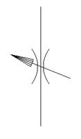
Needle Valve
A needle valve is what you would want if you needed to adjust the flow. (Note the arrow for adjustment.) These components are good if you just need to limit the flow but don’t really care if you have bi-directional flow or overrunning loads. Let me explain. If you are using a needle valve to limit the speed of a hydraulic motor, in theory you could put the valve on one port only. However, you will notice that you will get vastly better performance rotating the motor one way. Going the other way, you will see jerks in rotation. The reason for this is friction in the motor and the system it is driving. Granted, the average speed was what was desired, but the performance was not. I would now like to describe two new terms, metering in and metering out. Metering out is the method of metering the fluid coming out of a valve and going to the motor. This will give you poor performance because we are at the motor’s mercy for handling friction. Sometimes we may turn the motor at 500 psi, sometimes at 1200 psi. Who’s to say? Metering in is the better solution. Metering in (into the valve that is) forces the outlet of the motor to maintain a constant pressure. The inlet pressure can still fluctuate wildly but the motor speed will remain steady. To accomplish a meter in on both sides of the motor, we can’t use a needle valve anymore because the flow will be metered twice.
Adjustable Flow Control
Flow Control
Flow control valves were developed to have unrestricted flow out of the valve and metered flow back into the valve. The check valve is what allows unrestricted or ‘free flow’. (Free flow is from bottom to top). These come in both adjustable and non-adjustable configurations. One final thought is that these valves will build lots of heat especially with positive displacement pumps. You can minimize this by having a compensated flow control valve that will send bypassed fluid to tank instead of building up pressure until the relief valve kicks in.
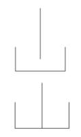
Reservoirs (or Tanks)
There are two types of tank schematics: pressurized and unpressurized. Unpressurized is definitely most prevalent in the market. One can infer that the pressurized tank is the one that is enclosed.
With a reservoir, you can also indicate if you want oil to be returned above (top) or below (bottom) the oil level in the tank. I’ll be honest, I don’t know why you would want oil returned above the oil level. Doing so tends to add air to the fluid (think about a fish tank). If too much air gets into the suction line, you can potentially make your incompressible fluid a little more compressible which leads to poor performance. The irony is that I almost always see the schematic indicate to return the oil above the oil level.
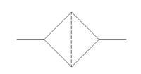
All oil should be maintained by the system and filtration is a must. It is a diamond with a dashed line indicating that the fluid must flow through a screen of some kind. Many filters will also have a spring loaded check valve in parallel so that if the filter is clogged, oil will bypass through the check valve.
Maintaining oil temperature is also essential. If the system is intended to be used in cold climates, oil heaters (right) are a must. The arrows point into the symbol indicating the direction of heat flow.
Heat Exchanger
Temperature Controlling Systems
A heat exchanger (above left) is used to reject heat from the system and the arrows point out. There are also temperature controlling systems that can either reject or add heat. This is represented with one arrow pointing in and one pointing out. It is important to note that these can be turned on and off as needed so that only one or none is active.
Pumps and Motors
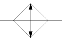
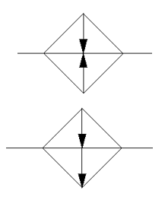
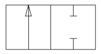
Pumps and motors are probably the most easily identifiable components on a schematic. This is always the first component I look for because this is where the magic starts. Pumps will have the arrows pointing out indicating that fluid energy is flowing out from the pump. Hydraulic motors have the arrows pointing in.
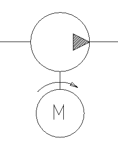
If a pump is driven by an electric motor, it can be shown connected to it. The direction on rotation can be shown. Remember that the rotation direction shown here is clockwise when looking at the pump shaft, not the motor shaft. Both pumps and motors can be fixed displacement or variable displacement.
Fixed Displacement Pump with Motor
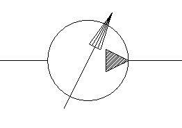
Variable Displacement Pump
Variable Displacement Motor
One cool thing is that you can actually have bi-directional pumps and motors. We can see why you would want a bi-directional motor, but why a pump? Bi-directional pumps are generally paired directly with a motor in a closed hydraulic system. Instead of returning the used oil to the reservoir, it goes directly back to the pump. There are a lot of winch applications that use this type of system.
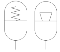
Accumulators are devices that store pressurized oil. This is prominent in systems that have a very high peak horsepower, but the duty cycle of that is low. A good example of this is the ‘Top Thrill Dragster’ roller coaster at Cedar Point. (image courtesy of daveynin on Flickr). Lots of power is used in a few seconds to launch this car over the hill. However, the cars only launch every 60 to 120 seconds so that whole time in between can be used to produce energy and store it in accumulators until needed. Accumulators come in two types, spring loaded (indicated by a spring) and gas charged.
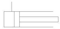
Cylinders
Cylinders are linear actuators that can produce large forces in small volumes.
There are generally three types represented in a schematic. A single acting cylinder is one where hydraulic oil is only supplied to one side (usually the bore) and either gravity or springs make it return. A bottle jack is a good example of this.
Single Acting
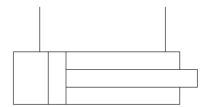
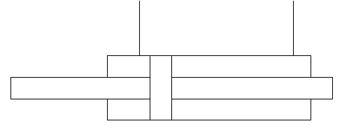
Double acting cylinders are the most common, and pressure can be applied to either side to make the cylinder extend or retract. Since the extend area and retract area a different on a double acting cylinder, you may get undesired performance. Double rodded cylinders are an answer to this because the area is the same on each side of the piston.
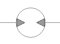
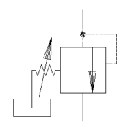
Controlling pressure is essential in all hydraulic systems. Every system must have a relief valve to protect hydraulic and mechanical components. In this schematic symbol, the pressurized fluid is on the top side of the valve. If the pressure is high enough to overcome the spring, the arrow will shift over and oil will flow through in this case, to the reservoir.
However, we can change the ports a little and get different performance. Instead of having the output flow go to the reservoir, we can make it power something else say a motor. This is a sequence valve. If I have a hydraulic drill press, when flow is turned on to the top side, perhaps I have a clamp that I want to engage first. I could connect the cylinder to the top side line and the cylinder would clamp in order to build up pressure. It is only after enough pressure is built that the motor would turn.
A pressure reducing valve is also an important hydraulic component. A recent system I designed had one side operating at 3000 psi and another side operating at 400 psi. I incorporated a pressure reducing/relieving valve where the left port had the full system pressure of 3000 psi. The right port was set to give me reduced pressure of 400 psi. If pressure in that line rose, it would relieve that pressure to tank through the bottom port.
Load Holding Valves
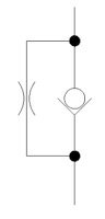
Any load holding valve will be based on some form of a check valve. A check valve will allow flow to move easily in one direction, but not in the other. This is great….if we want to hold the load forever. Often that is not the case, so we need a method of bypassing flow.
The pilot to open check valve, commonly referred to as a PO Check, is used to unseat the poppet. (Spoiler alert: check valves don’t use balls because they are super difficult to make and don’t seal well. A poppet is a segment of a cone shape that seals much better.) Generally, if a directional valve uses work port A to lift a load, work port B is used to lower the load and unseat the PO check valve.
If both directions need to be locked, you can use a double PO check valve. This is a manifold that combines two PO check valves and simplifies the external plumbing needed by incorporating the cross pilot lines.
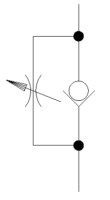
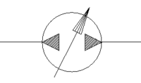
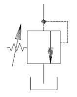
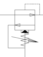
There is one major downside to using a PO check valve: Temperature. If your need is to have load holding in both directions, a PO check can actually create extremely large pressures. Imagine the situation of setting up a device under load early in the morning. The load and position don’t change all day, but the temperature gets 30° to 40° warmer. The oil will expand creating pressures that can exceed the motor or cylinder’s capabilities. It is a bad situation. Luckily, a counterbalance valve comes to our rescue. A counterbalance valve allows free flow into the motor or cylinder through a check valve, but there is a specialized relief valve on the way out. If the pressure in the cylinder is too high, it will relieve pressure (port 2 to 1) until the valve closes. There is also a pilot port (port 3) to open a path for return oil flow.
The cool thing and the thing that will cause a lot of headaches is that you can tune the performance of the system by taking advantage of the metering in functionality available. This is controlled by two things: pilot ratio and flow capacity. I don’t have enough time to get into it now, so we will save that for another article. Counterbalance valves are available in single or dual configurations.
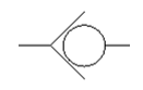
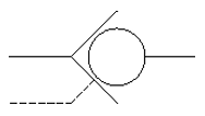
Shuttle valves are logic elements that allow two (or more) things to signal something else. A shuttle valve is basically two check valves with only one ball (yes, poppet, I know). The higher pressure will force the poppet to close the lower pressure side and send pressure and/or flow to the perpendicular path. Compensated valves are a good example of this, where each valve section will send the compensator pressure back to the pump to determine how much pressure is needed. The pressures are compared to each other using shuttle valves and the highest pressure wins.
Directional Control Valves
Directional control valves are the pillar of hydraulics. These allow fluids to change direction and flow paths. These valves are specified by their positions and ways. Positions are the number of discrete configurations of the valve. Ways are the number of ports the valve has. A two position, two way valve would be used to turn on and off flow.
2 Position, 2 Way
A three position, three way valve could be used to fill and discharge an accumulator. You would want high pressure oil to fill and then connect to a low pressure path to discharge.
2 Position, 3 Way
A two position four way valve can change the direction of fluid where you could change the direction on a motor or cylinder. These valves can have a soft shift option (left) where a phantom third position allows for a smooth transition as indicated by the dashed lines between positions. This extra position ties all the ports together to neutralize pressure and minimize the momentum effects when reversing flow.
2 Position, 4 Way
2 Position, 4 Way with Smooth Transition
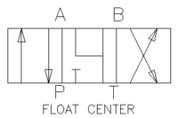
A three position four way valve offers an off position so that the system can rest. This center position can come in numerous configurations that can satisfy almost any requirements. Please read my article on directional control valves for more information.
All positional valves need to be actuated to perform a function. We will start with mechanical actuations. From left to right they are: push button, mechanical action, lever, foot switch and mechanical switch. With the exception of the lever and push button, these are getting harder and harder to find. Electronics has improved so much in the last twenty years that it is far easier and less expensive to run wires to electrical sensors than hoses to hydraulic components.
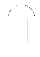
Push Button
Lever Actuation
Mechanical Action
Foot Switch
Mechanical Switch
Pilot pressure and electric actuation are the dominant forces in the market and will be for some time. Electronic control systems allow for the precise application for pilot actuation (left), where low pressure shifts the valve, and electro-proportional actuation. The right schematic symbol is for a solenoid operation. A solenoid is a non-proportional signal that fully moves the valve. For proportional operation, other methods are used and an arrow would be drawn through the symbol.
Pilot Pressure Actuation
Solenoid Actuation
Many valves are biased to one direction or the center position. Springs are the method of accomplishing this. With all these controls, you do not need to have actuation on both sides.
Spring Centered Valve
If you don’t want the valve to move when deactivated, you can add detents (center and right) to make sure the valve stays in the same location. Detents are usually a spring loaded ball (yes, actual ball) that will lock into a groove in the valve spool.
2 Position Detent
3 Position Detent
Miscellanous Components
There are a few components that don’t fit into any specific categories that I would like to share now. Pressure gauges are the most common. They will give the pressure of the line where they are installed. Be aware of the effects of flow in the system. I recently had to relocate a pressure gauge because the pressure drop due to flow was giving me false readings. I moved the gauge to the component I was interested in and the false readings stopped.
Pressure Gauge
Temperature indicators look like thermometers. They can be placed throughout the system like pressure gauges, but many designs just monitor the reservoir temperature using a sight gauge. A sight gauge (not shown) will indicate the oil level and usually the temperature in the reservoir.
Temperature Gauge
Pressure switches are switches that change state when a certain pressure is reached. Please note that hysteresis is a problem with these so if a switch is set at 400 psi when rising, it may not switch off until 350 psi when falling. They can come in Normally Open and Normally Closed configurations and fixed and variable pressure settings.
Pressure Switch
The last symbol is a manual shutoff valve. These are generally low pressure devices and are used on the suction and return lines near the reservoir to allow for easy changing of the oil and filter. Be sure to keep these open. Bad things can happen otherwise.
Manual Shutoff
Wow, there sure are a lot of symbols, and as I mentioned, this list is not exhaustive. Hopefully, you can already begin to see how some of these components will work together like how a directional control valve will control a cylinder.
4. Identify the flow path at a de-energized state
As I mentioned, looking for the pump(s) in a schematic is where I start. Trace lines outward from the pump until you hit a closed valve. Repeat until you are back at the reservoir or run out of paths. I then look to make sure that the system has the other three critical components. Once satisfied that the four components are there and correct, I will start to look at the de-energized state. When all components are de-enegrized, is flow allowed to return to tank or does it build system pressure or is it somewhere in between? I usually trace this out with a highlighter. If I have a fixed displacement pump, I want that oil returning to tank at near zero pressure. If I have a variable displacement pump, all the flow paths should be blocked and our compensator pressure set at least 200 psi less than the relief valve.
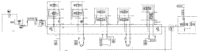
In the Example 1 (below), the fluid with flow through the first work section comes out through work port A and into the manifold from the right. At this point it is stopped at all seven valves. It also goes through the pressure limiter and is stopped at the directional control valve. This system allows pressure to build fully and indicates that we need a variable displacement, pressure compensated pump which we have.
5. Determine what happens as each valve is moved
Now that we have our de-energized state identified, we should then energize components one by one. (Sometimes there may be an enabler that needs to be energized as well. This is the case with Example 2.) Keep track in each section for what happens to pressure and flow and what the desired outcome is.
Section 1 of the manifold will reduce the flow (meter out) by activating the top valve to pilot open the larger valve below it. This will then send flow out port B but not before sending it through a flow control valve.
If we activate Section 2 to pressurize the A port, we should see the top valve activate the larger valve below it. This flow will go out port A and pressurize the pilot port on the counterbalance valve. Once outside the manifold there are two flow control valves that will control the motion of the motor by metering the fluid in. There is also a pressure switch that will indicate if the motor has stalled (we are only looking for the signal when the B port is energized). The other three ports on the valve are similar so I won’t go into detail here.
The two valves on the right beyond the pressure reducing valve control a cylinder. If the right coil is activated on the left most valve, the cylinder will retract slowly by gravity as metered by the needle valve. However, if the valve on the right is activated, the needle valve is bypassed and the cylinder will lower much faster.
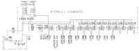
As mentioned, this schematic has a positive displacement pump and needs to have an unloader valve closed before any motion can happen. This is done by energizing S7 which must be done with any other solenoid.
If we energize S1 and/or S3, we will be able to retract the left and/or right extension cylinder. However, when we activate S2 and/or S4, we do not want to extend before all the cylinders on the bottom have been retracted so that we avoid collision. To do this, we use a shuttle valve so that the flow from S2 and S4 do not contaminate each other. The flow then goes on to apply pressure to a counterbalance valve and retract all the cylinders.
Note the center position of the directional control valve (3 pos. / 4 way) activated by S5 and S6. The P and A ports are blocked, but the B and T ports are connected. This is done specifically so that we have a path to get the oil out of the cylinders. Once all of those cylinders have retracted, only then will there be enough pressure to overcome the sequence valve and extend the extension cylinder(s).
Energizing S5 will retract all of the cylinders as S2 and S4 will, but it will not extend the extension cylinders because of the shuttle valve.
When S6 is energized, we will start extending the cylinders in a prescribed way. (Note that we did not care how the cylinders retracted.) The flow will come out of work port B through a flow control valve. Since we have a positive displacement pump, we didn’t want to have the remaining oil bypassed over the relief valve. We did this by using a compensated flow control so that our extra flow would go right to tank (port 2) at a much reduced pressure. The metered fluid (port 3) then goes on to a counterbalance valve where it will free flow through the check valve.
At this point, Group 1 is activated. Group 1 is two horizontal clamping cylinders and will extend until 300 psi is built up. At that point, Group 2 is activated where four vertical and two horizontal clamps are actuated. At 400 psi Group 3 is activated and so on until we get to Group 6. When group 6 is activated, if Solenoid S8 is not active, it will extend the cylinder. If S8 is active, the section will not press and it prevents flow from reaching anymore sections. S8 is triggered by a proximity switch that detects how long the work piece is. If there is material there, S8 will disable and the section will press.
6. Activate multiple valves at a time to see if there are unintentional consequences.
Unintended consequences are very difficult to see and predict. The real challenge here is to learn from these so you don’t make them twice. One common occurence is energizing both sides of a directional valve. Usually there is no damage done, but your control system should be configured to eliminate this hazard. If using relay logic, you can have one relay to turn on power to a valve and another to select the direction.
In Example1, there was an unintended consequence when I activated Section 1 and the B port of Section 2. It glares at me now, but before it was very difficult to see until the system was built. On the motor, I have flow control valves to control the speed of the motor. However, I want to limit the speed of the motor before stopping it (the location of stopping is important.) I do this by activating Section 1 about a foot before the stop point thus reducing the speed. However, the reduced flow is lower than that of the meter in flow control. The result is a low flow metered out condition and my motor jumps to its stopping position. We are taking steps to correct this.
In Example 2, the two position, three way valves should have been configured so that the positions were opposite of each other. The reason for this is to prevent damage to the machine. If a wire is broken to one of the solenoids, extra sections will press and may cause potential damage to the machine. To minimize this risk, we added extra protection to the wires, ran larger gauge wires than needed and added inspection of the wires to the monthly preventative maintenance checklist.
Conclusion
Reading schematics is a very scary thing, but remember to relax, you are smart and mommy and daddy love you very much. You got this! Just work through it slowly and don’t be too quick to ask a question. When doing work like this, I often wait until I have a good series of questions before I ask for help. This way I will have spent more time working through the schematic so that my questions are thorough and won’t waste a coworker’s time.
Once you master the skill of reading prints, you will be able to critique and create your own systems. Remember to use a systematic approach and always have your work checked before you purchase components. So, grab your highlighters and find some schematics to analyze!
Beam Calculations Made Easy – From Free Body to Stress Analysis
There is hardly a week that goes by where I don’t need to
calculate the stress on a beam. Beams
are everywhere and come with the challenge of many different loadings and
supports.
There are 5 steps to
calculating the stress on a beam:
Determine the loads
Determine the support conditions
Draw a shear-moment diagram or look up in a
table
Calculate the section properties
Calculate the stress and apply design
factor.
With these five steps you will be able to setup and
calculate most beams. With a little practice,
you will be able to go through the steps with ease and greatly reduce the time
it takes to calculate the stresses.
Let’s dive into each step with more detail!
1.
Determine the Loads
This can be the most difficult part of the process because
sometimes the loads are unknown or the angle changes with respect to the beam
with time. Perhaps there are many loads
that occur on the beam, but at different times.
With each case mentioned, we are going to have to make some
assumptions.
This can be overwhelming! I know
because on the equipment I used to design, for each major component there was
on average four positions it could be in and a side load component could be
applied in two directions (so 8 cases total).
My beam calculations for this were very thorough, but exhausting. Most importantly, they were worth it. There were two cases that fought each other
making it difficult to come up with a solution.
If I had not done the analysis on all 8 cases before testing, we would
have had costly delays in testing and a longer time to product launch.
If the loads are unknown, is it because they are working
loads or abuse loads? In some abuse
conditions, it is possible to have the design factor account this. What is the design impact of using a worse
case load? Would my section need to be
increased much, if at all? Could I
reshape a stiffener or gusset to carry the extra load?
If load angle to the beam is a consideration, choose the
loading that is more perpendicular to the beam.
The beams are much better with axial loads than moment loads. As a result, a load more perpendicular to the
beam axis will have the greater impact.
If you have multiple loads that change over time, you will
need to have multiple cases. This can be
tedious, but it will pay off in the long run.
Once you have all the cases, usually 2 or 3 stick out as ones that need
to be monitored.
Load Types
Image courtesy of Wikipedia commons
There are three types of loads that can be applied to a
beam. They are point, distributed and moment loads.
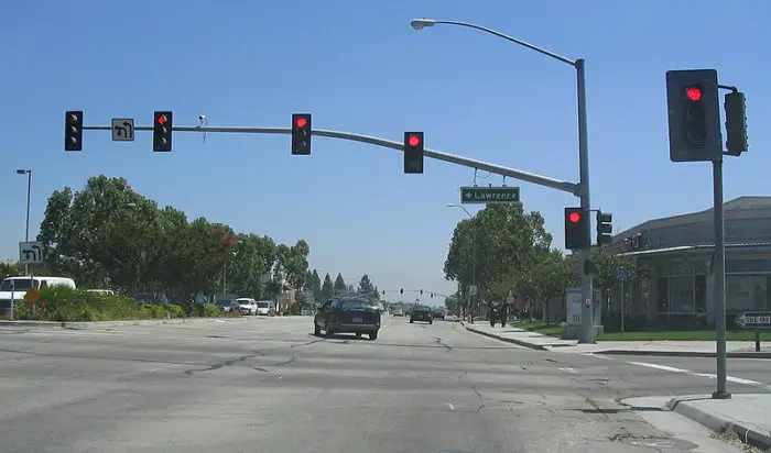
Point loads are the most common because they are applied to a beam
at a very small location with respect to the length of the beam. If we considered a traffic light reaching
across multiple lanes of traffic, there could be several point loads from the
traffic light assembly.
A distributed load is a load that is applied over a wide
span of the beam. The load applied with
force per unit length and generally is lb/in or lb/ft (watch your units
here). It may be applied over the entire
beam or a small portion of it. This is a
good method of simulating the weight of the beam. The load does not have to be equal over the
entire span, but can increase or decrease from one end to the other. In our traffic light example, the cross
section of the beam may increase steadily from the end to where it joins to the
vertical beam. If we were going to
simulate this in our calculations, we may assume it starts off at 10 lb/ft and
increases linearly to 20 lb/ft at the vertical beam. The distribution does not have to be linear,
but there are more tables that have linear distributed loadings so if you don’t
want to do the math, try to make it a linear application of load (more to come
on that). Wind and snow loads are great
examples of distributed loads.
The final type of loading is a moment load. This is a case where a moment or couple is
applied. In our traffic light example,
the vertical beam will have two moment loads imputed where the horizontal beam
attaches. They are from the weight of
the lights and the weight of the beam.
This moment load is constant down the length of the beam and the
strength of the beam doesn’t depend on how high the cross arm attaches. Another example is in a log splitter where
the cylinder is pressing (applying load) at the same fixed distance away from
the beam axis. The load applied by the
cylinder creates a constant moment along the entire length of the beam.
Once you have your loads, create a free body diagram showing
each load and where it occurs on the beam.
It doesn’t have to be exactly to scale, but it helps if it is
close. Be sure to leave room directly
below the beam so that we can draw our shear-moment diagram!
Before I move on, I wanted to point out that each of these loads are assumed to be perfectly in line with the centroid of the beam. These loads produce bending forces internal to the beam called moments. If a load is off center from the centroid, a torsional moment is produced that will twist the boom. Care must be used to when adding torsional loads to a beam. Beam shapes like flat plates, angles and I-beams are not able to carry high torsional loads. Steps can be taken to improve these shapes, but the best solution is to try to change the cross section from an open to a closed shape.
2. Determine the support conditions
Supporting the beam is crucial to determining the stress on
the beam. There are seven main beam
types with three support conditions. The
three support conditions are: supported (or simply supported), where the beam
can pivot, but not translate at the support; guided, where the beam is allowed
to translate, but not rotate at the support; and fixed, where the support
cannot translate nor rotate. Another
case is ‘free’, where there is no support…so it’s not a support.
The seven main loading conditions are:
Fixed at one end, commonly called cantilever
Fixed at one end and guided at the other
Simply supported at each end
Fixed at each end
Fixed at one end and supported at the other
Simply supported with overhang
Three or more supports
Most of these cases are tabulated in reference books, (see the Resources page). These are a huge timesaver, but not all cases are there and occasionally, you need to go back to the basics for the load case you need. The last case is special in that it is not statically determinate and super complicated to setup and calculate. I encourage you to avoid multiple supports wherever possible for this reason.
3. Draw a
shear-moment diagram or look up in a table
So whenever possible, look up your load case in a
table. These are generally available in
multiple resources and are valid. I know
that I am not perfect so if I tried to derive the equation, I probably would
get a sign wrong and screw the entire thing up.
Many times you can combine multiple beam loading cases together to match
your case. With cases that are
statically indeterminate, like fixed at each end, this can be very challenging. This subject is worth of its own article, so
it will not be discussed here.
If your statically determinate case (cantilevered, or simply supported) is not in a table, you can easily create your own shear-moment diagram and visually find the highest moment on the beam.
Image courtesy of Wikipedia commons
The traffic light example would not be in our books because
we have four lights, the street sign and the weight of the arm. The turn sign I don’t see being too heavy so
I will ignore it. Let’s assume some
numbers here and go ahead and calculate it.
Lights: 300 lb. each (yes, these things are
large and heavy when viewed on the ground) at 132”, 180”, 276” and 324” from
the vertical pole.
Street sign: 100 lb. at 96”
Pole: The section gets larger as it gets closer
to the vertical. Say 2 lb/in at the
skinny end and 7 lb/in at the pole. Now
with this there is some circular logic going on here. If our stress comes up too high at the end,
we will need to increase our section.
Most times, we will need to increase the weight per foot to
compensate. This leads to more load on
the structure. Yes, wash, rinse, repeat. Often the weight of the structure is ignored
for this very reason, but in this case, I want to show the effects of multiple
loads.
So we can start laying out our shear moment diagram in sections keeping like items together. All of the point loads calculate nicely together so we will combine them. We will then split apart the distributed loads from the point loads. The distributed load will also be separated into a constant distributed load with a magnitude of 2 lb/in and a linearly increasing load with a maximum of 5 lb/in. We do this because these are readily tabulated in many reference tables. Once we have calculated the moments for each of these cases, we can simply add all of them up at the end. When I look at this traffic light pole, I am concerned with the loads where it connects to the vertical member and at the second light from that (180”). Let’s calculate the moment at each of these points using our shear moment diagram.
In the calculations above, we laid out each load and the
distance from the pole. Here you can see
that when we work from left to right, we keep adding weight to the pole and the
moment increases more and more. We can
easily draw a shear diagram by increasing the shear force 300 lb. for each
light as we move right. To calculate the
moment, we then integrate (yup, calculus) to get the moment. This is easy calculus though. Remember the integral of a rectangle is a
triangle; the integral of a triangle is a parabola (x^2), the integral of that
is x^3 and so on and so forth.
So now we divide our shear diagram into multiple smaller rectangles by drawing vertical lines moving from left to right. The first block is 300 lb. * (324 in-276 in) = 14,400 in-lb. The second block is 600 lb. * (276in-180in) plus the previous block equals 72,000 in lb. We continue to do this for each block until we get to the base where we have our moment total for this block. The resultant moments are 72,000 in-lb. at 180 in and 283,200 in-lb. at the vertical.
As we add in the distributed loads, it gets a little more
complicated because they aren’t linear any more. Our constant load (2 lb/in) will increase as
we move to the right and form a triangle.
The slope of the line will be w (2 lb/in) times x. At the base it will be 684 lb.
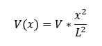
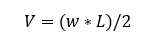
The distributed load that constantly increases to w (5 lb/in) will follow the equation (I looked it up in a table):
Where V is the shear force at the end of the beam and is equal to:
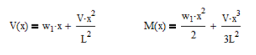
In our case, V is 810 lb. We now need to integrate these two components which we will do mathematically. This is easy calculus so don’t get worried. Integrating polynomials is simple because you just need to add an exponent to x and then divide the term by that new exponent. This leads to the equations:
Ok, so you can see why, I recommend
sticking to the tables. So from our
equations, we find that the moment at 180 in is 28,416 in lb. Now you may have just said, “Corey, I
calculated 47,400 in-lb. What happened?” Good question. The answer is simple, we marked our distances
starting from the vertical moving left, but then we started counting our x
dimension from the end of the pole moving right. This greatly simplifies the calculation, but
it can cause some confusion so be on the
lookout for changes in coordinate systems.
Luckily, if we didn’t catch this, we would end up with a stronger pole,
but that is not always the case.
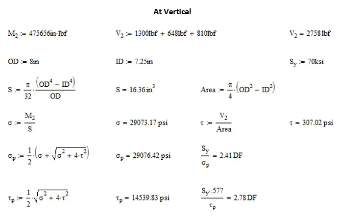
Our second equation yields a moment of 192,456 in lb. at the vertical member. When we add these to the moment from the point load we get 100,416 in lb. at 180 inches and 475,656 in lb. at the vertical member. You can see here that the weight of the beam was a significant component in the loads on the beam. I’m glad we included it. Off to the next step.
4.
Calculate the section properties
The section properties are the mechanical properties of any
section. To properly select a cross
section of interest first do a visual inspection and see if there are locations
that pop out. I chose two locations on
the traffic light pole. The most obvious
location was where it attaches to the vertical member. I chose it because I knew the moment would be
highest here. The other was at the third
light from the end (180 in), because it had some moment, but the cross section
looked weaker there.
When calculating your
cross section, be sure to cut perpendicular to the section. The traffic pole has a curve to it as it
reaches the vertical member so we don’t want to cut our section vertically, but
at an angle perpendicular to the tube axis.
If we don’t cut normal to the axis, we end of getting a larger cross
section than what is actually there. In
this case a tube would become an oval with larger height and thicker top and
bottom material. Not a good thing to do.
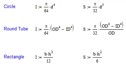
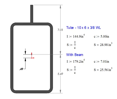
There are two components of the section that are important. The first is the distance from the centroid to the outer fiber of the material. If the beam is horizontal, it will be to the top or bottom of the section. This distance is referred to as ‘c’ and has the units of length. The other component is the area moment of inertia or the section’s resistance to bending. The larger the section, the more resistance there is to bending. This is specified as ‘I’ and has the units of length^4. The area moment of inertia is a double integral of the area from the centroid. It is far more calculus than I am willing to do so you can look in the back of many textbooks or do a quick web search. The most common shapes I’ll list here and they are easy to remember. (I didn’t even have to look them up for this). The section modulus, S, is simple area moment of inertia divided by the distance to the outer fiber (I/c). This is one thing that I will never forget due to the late Dr. Tommie Thompson. He put this on a test having never mentioned it in class and there only being a short mention of it in the textbook. Naturally, my test grade went down by almost a full letter due to this small oversight.
One thing that I really want to drive home on this is that the area moment of inertia really drives deflection. The larger the value of I, the stiffer the section is. However, the section modulus, S, drives the strength of a beam. It is sometimes difficult to explain how adding material can weaken a structure. I had a client that was insistent that adding a bar to the top of a rectangular tube would make his apparatus better (meaning stronger). And he was right in one way and wrong in another. The bar definitely made the beam stiffer, but at the same time, it was weakened because it took material from the outer fiber and place it closer to the centroid. I can’t remember the exact details, but the beam was similar to what is shown below.
The ratio of the area moment of inertias shows an increase
of stiffness around 24%, but the overall strength of the section is reduced by
almost 12%. My first caution is to make
sure that you don’t inadvertently do something like this to your structure by
adding a gusset. My second caution is to
make sure that you carefully choose your materials. If the tube is 46 ksi yield, adding a gusset
of matching strength is bad enough, but if that gusset is A36 material, that
makes it even worse.
In summary, you need a well-defined cross section and know
the area moment of inertia and the distance to the outer fiber or the section
modulus before you can continue.
5.
Calculate the stress.
Most of us remember that there is a neutral axis when
bending loads exist. This is a line that
goes through the centroid of the section.
As we go from the centroid out, our stress increases linearly despite any
changes in cross section. I mention this
because there may need to be several locations where stress needs to be
checked. A good example of this the tube
with the plate added to it above. If the
plate is 100 ksi yield and the tube 46 ksi yield, I would want to check the
stress at the very top and very bottom of the section.
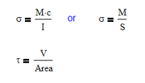
From here, calculating the stress is a walk in the park. The governing equations for calculating normal and shear stress in a beam are:
Since we already know the moment, M, and the section
properties, we can just plug those values in and go. For long beams, shear stress is usually a
very minimal contribution to the overall stress. But, it is usually a larger component on
shorter beams. This is why it can be
ignored in most cases.
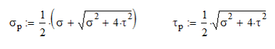
Once we have our shear and normal stresses, we can combine them using Mohr’s Circle. I’ll be honest with you, Mohr’s circle is presented in a way that is way overcomplicated and I have tried to simplify it. Please watch my video on Mohr’s circle for a simplified approach. The resulting governing equations are:
These stresses can then be compared to the yield stress. The normal stress is directly comparable, but the shear stress need to be modified by a factor of 0.577 to account for a material’s shear strength being roughly half its yield strength. (It’s all explained in the video, you should watch it)
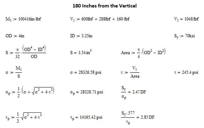
Going back to our examples, we wanted to look at the stress at 180 in from the vertical and at the vertical. Here is how I would calculate the stress and compare it to our yield strength (assumed to be 70 ksi)
You might have guessed that I randomly
selected a tube cross section, and I did.
There is no significance to the design factor in this example. I am unaware of any structural design
criteria for traffic light poles. I’m
sure whatever standard there is it contains requirements for wind, snow and seismic
loadings as well. Had we been doing a
full design of this beam, we would have wanted to include all of these loadings
and considered loadings in multiple planes.
All of this is a subject for another article.
Design Factors (A
quick word)
Design Factors, also known as Safety Factors or Margin, are
cushioning between the actual loading and the calculated loadings. Often you will find a specified factor listed
in the specific standard that is for your particular application. Often times, these are based on a 2:1 design
factor for a ductile material. The
reason for this is that 2:1 is usually under the fatigue endurance limit for
the most common steels (under 100 ksi yield strength). If this design factor is adhered to, issues
with fatigue rarely show up and if they do, it is usually because of a large
stress concentration or unintended loading.
Some standards would specify a base design factor and then
add on factors for stress concentrations and dynamic loadings. These numbers would all be multiplied together
to get the design factor used in hand calculations like we just did. However, with the advent of Finite Element Analysis
(FEA) in the last twenty years, we can simulate stress concentrations and some
dynamic loadings. As a result, more and
more standards are being rewritten to remove these extra factors.
There are other standards, some in the oil and gas industry,
where the maximum load is unknown so a very low design factor is used on a very
high theoretical load.
Other things to consider are loads produced by wind, rain,
snow etc. Excessive dynamic loads can be
a significant stress component for trailers and off road equipment.
If there isn’t any specific design standard here is my
general rule of thumb for design factors:
General design 3
: 1
Non-working load cases 1.5 : 1
Trailers or off road devices 4 – 6 : 1
Conclusion
I remember in school thinking how difficult it was to calculate the stress on a beams and how time consuming it was. I now laugh at those days, because it seems so simple to me now. Following these steps allows you to focus on each part of the beam and how that effects the stress. If you do it often enough, it will become second nature very soon.
Simple Gear Design – Comparing Spur Vs Helical Tooth Forces
Hi and welcome back to Mentor and Engineer. We’re still talking about gears here. Still excited, woohoo! And now we’re going to talk about making sure that your gears mesh together. And so, before we can do that, we need to talk a little bit about terminology.
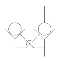
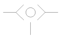
Alright, so the first thing I want to point out is these things called lands right here. Alright, this is a bottom land and a top land. They’re more or less a flattened section of our tooth. And then you will also notice that as they mesh together, you’re going to have a gap here, you’re going to have a gap up there, and you’re going to have a gap on the back side of the gear. Now I have my gear rotating clockwise here, which means this one’s going to rotate counterclockwise, and it’s pushing right here, and it’s pushing a little bit right there.
And you want to make sure that there’s a gap everywhere so that you don’t bind the teeth. It’s very important to have a gap right here so that you will be able to make adjustments. You can also adjust that gap by bringing these two gears closer or farther apart. You never want to get to a zero tolerance. So, this right here is where back glass comes into play.
I can adjust the center distances to increase or decrease that gap as I desire. Moving on, we’re going to talk about the pitch circle. The pitch circle is these two lines here, these dotted lines. That is right at the center here. These two will be tangent to each other.
That’s the theoretical angle where the gears mesh together. From there, we can determine how far our gears need to be apart based on their center to center. This value of a pitch circle will come from the manufacturer. and they will be something they readily give and it will allow you to figure out how far apart they are and you use this formula that the pitch circle represented by d d1 divided by 2 d2 divided by 2 equals the center to center distance of the two gears all right
and that’s just saying that the radius of this gear and the radius of that gear have to eat it may have to add up to be double that so you get that tangent line there no big deal we can all do that all right the second thing that we’re going to need to talk about is diametrical pitch and this is represented by the letters p and D, both capitalized. Sometimes you’ll just see the letter P for the pitch diameter. I like to use both just to indicate that’s exactly what I’m talking about. And that is the number of teeth, and that is divided by the pitch circle of the tooth, and that’s represented by lowercase d.
So, let’s do a little example. I have Lego gears here and I have two gears, and I know that they need to mesh together because I see the mesh and I want to figure out what is the diametrical pitch. So, I’m going to use unstandard units here. Just because I can count these very easy, I’m going to consider each space one.
So, this large gear right here, we’re going to start there. I just counted. It’s got 40 teeth. and it has from the center one two and a half spaces all right so I’m going to need to multiply that by two
and I get five, so I get 40 teeth five spaces and that equals eight, so that’s a pitch diameter of eight. Alright, on the small one, it’s got 24 teeth, and it is one and a half, so multiply by two, that’s three, so I’ve got 24, excuse me, I can’t write, 24 divided by three, and that also equals eight. Now it is very important that these two numbers add up are the same. That is how a gear will match.
The other thing that tells me if a gear will match or not is the pressure angle. So those both have to match. So, if I have a pressure angle of 20 and one of 14 and a half, those will not work together. If I have a pressure or a diametrical pitch of six and eight, those will not match together. They both have to match.
That is the only two things that have to have happen. The final component of this video is going to be doing the gear ratio. This is the ratio of the two gears and how the input drives the output. It’s very simple. It’s all based on the number of teeth.
Our ratio is going to be the number of teeth on the output gear. over the number of teeth on the input gear. So, in this case, I’m going to drive the 40-tooth gear by the 24-tooth gear. And that gives us a ratio of 3 to 5. So, I can divide both of those by 8, and I will get there.
Or what is that? 1.66. So, in our example, let’s just say that our input Gear is running at 100 RPM. All right, we’re going to do our output, which is V out equals V in over our gear ratio. All right, so we get, what is that?
It’s exactly 60 RPM. 60 rpm out now we can just use that formula to figure out you know so we get we will also get increased torque now it’s not exactly a one-to-one ratio because there is a power that is lost between the two gears and we’ll talk about that more in our next video so thank you for watching please stay tuned thanks bye.