In this video, Corey demonstrates different types of gears using Legos and what they are used for. He also details pressure angle and why that matters.

Check this Out
In this video, Corey demonstrates different types of gears using Legos and what they are used for. He also details pressure angle and why that matters.
This article is going to be a bit more technical than the previous article about fasteners, “The Magic of Fasteners.” I’m going to try to keep it as simple as I can, but this topic is so deep and complex. My intent is to give enough insight to make it practical, but not to cover every aspect or go into great depth.
Hydrogen embrittlement, stress corrosion cracking, mismatched hardware, fatigue and mechanical failure are the five ways that bolts and screws fail. Nearly all failures can be prevented by selecting the correct fastener and understanding the preload necessary.
We will be exploring the 5 ways that fasteners fail and spend the rest of the time trying to avoid it. Good bolted joints are possible to predict even before a single part is fabricated or a single strain gage is laid. However, my first rule of applying a fastener is this: if you can avoid using a structural fastener, do it! If you get nothing else out of this article, I will be satisfied. I don’t say this lightly either, because structural bolted joints are difficult to design, require expert insight and will generally take up a majority of your product support time. Designing a welded joint is much simpler and stronger. However, that is just not the world we live in, so here we go.
This is a very serious type of failure that can take place when a bolt breaks off and projects like a rocket due to the high load on it. This typically occurs within the first hour of the initial torqueing of the bolt. The reason this issue occurs can be linked to the electroplating process. As the water has a lot of hydrogen and oxygen in it, the electricity frees them up and they permeate the steel and start eating away at the material of the bolt. The result is in the weakening of the material and failure of the bolt head. Not good.
We definitely want to avoid this so we need to know the causes. All three of these need to be present for hydrogen embrittlement to occur.
Although we want to entirely avoid this issue, the only positive element is that it typically occurs early in the assembly process before the product gets out into the field. In order to prevent hydrogen embrittlement, it is possible to bake all of the hydrogen out after the plating process is complete. This requires the fasteners to be heated to a certain temperature until all the hydrogen is burnt out of the part. Another way to avoid this is to have fasteners mechanically plated. This is a process where fasteners are turned in a drum (think concrete mixer) with zinc powder and the zinc is pressed into the fastener.
As a result of chronic hydrogen embrittlement issues, the United States passed the Fastener Act of 1990 that instated manufacturing practices and forced traceability of fasteners in an effort to protect the public.
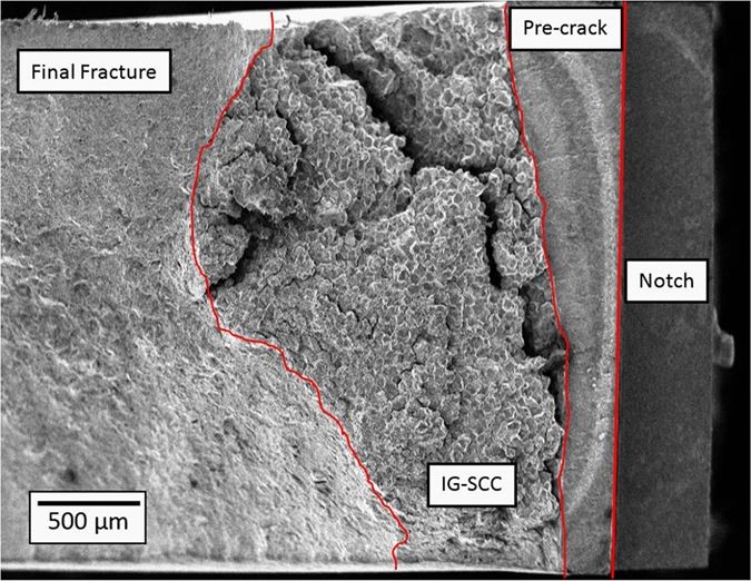
This type of failure occurs in a similar way as hydrogen embrittlement because the head will break off. The main difference in symptom is it can take place in the first 24 hours of torqueing and up to one or two months following. A good way to prevent this type of failure is to routinely do torque checks on the bolt. It is caused by an electrolyte which can be from how the bolt was manufactured or if it was exposed to certain chemicals.
Before we move on to the next failure mechanism, I want to issue this warning; if you need a high strength (stronger than grade 8) bolt for an application, something isn’t quite right with the design. Grade 8 fasteners are plenty strong, usually far stronger than the parent materials. You may need more fasteners or larger size fasteners in the joint. I say this because on the surface, switching to high strength fasteners makes sense, but you’ve now introduced a new potential problem of stress corrosion cracking and hydrogen embrittlement. These can have worse complications when a field population is considered.
This type typically manifest itself as a general failure when the proper hardware is not matched. To avoid this, make sure your bolt and nut grade are the same and that you are using a hardened washer if needed. If your design has the tendency to cave a washer, consider using a hardened washer or a custom thicker washer. Avoid washers that have burrs or sharp edges on them.
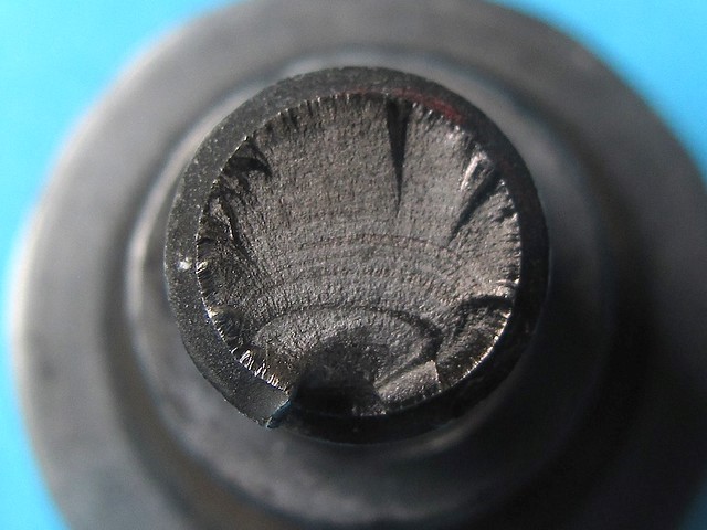
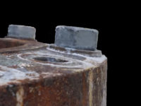
This type of failure occurs when the mechanical limits of the bolt are exceeded over time. The main causes of fatigue failure are higher stresses than expected or inadequate bolt pre-load. The higher stress may come from uneven loading of the fastener. If a moment load is applied, part of the bolt may relax while the other half is double loaded. If you examine a failure, you will see “velvety” portions of the break. This velvet surface is where the fatigue has been occurring. In the picture here, you can see that the fastener was firmly connected at the bottom. By analyzing the large sections of velvety texture, we can conclude that bottom stresses were pretty low. It is likely that this fastener had a moment load on it, which should be avoided.
Possible solutions for fatigue are:
Measuring the stress on a fastener is a complicated and tedious process, but on large project with critical fasteners it may prove essential. If actual data is not available, you can use calculated data to predict fatigue life. I would recommend calculating the theoretical maximum load than increase my preload and see where fatigue is no longer an issue. In order to calculate fatigue, I typically use the ASME Elliptical Equation, because it tends to fit empirical data better than the other, sometimes simpler models.
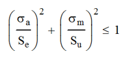
Where σa is the alternating stress [(σh-σl)/2], σm is the mean stress [(σh+σl)/2], Su is the ultimate strength of the material and Se is the endurance limit of the material. The endurance limit is generally half the ultimate strength, but there are corrections that need to be made for surface finish, temperature etc. We will not be discussing fatigue to this level in this article.
This occurs when the bolt breaks right after the shank turns into the threads. It typically occurs due to the bolt being too small, high torque, or the joint not being designed correctly. Unless the bolt is strictly designed as a shear member, it should never break in the shank. We will spend the majority of this article addressing the prevention of this issue.
Well this just makes sense; if the bolt has rusted away, it won’t hold a load.
A bolt’s number one enemy is rust, since the overwhelming majority are made of steel. Most steel fasteners have some sort of coating on it which will turn white or gray, but the type of corrosion that we are concerned with is called ‘red rust.’ The method for evaluating the time to red rust is by using a salt spray chamber. In this chamber, a fine mist of salt is sprayed on parts continuously. Once red rust appears, the test is complete and the hours are logged.
Generally, exposure to chemicals or other substances that cause rust within 50 hours is not a good coating for outdoor applications. Once you are able to get around 100 hours without rust occurring, then you are getting some good use out of that bolt.
In the salt spray test, the white or gray is a lesser type of corrosion that doesn’t directly lead to failure. It is simply materials other than steel corroding first. This corrosion order is based on the galvanic chart.
Read this article for more information.
There are a number of different ways that a mechanical failure will raise its ugly head. Here are the most common.
This is probably the most overlooked portion of fastener design. There are only two main principles to learn:
You should not engage the first three threads after the shank because it causes a stress concentration. In this image, you can see that the shank tapers off gently, but if the nut engaged on the first thread, the stress needs to make a sharp turn. If we wait until the third thread, this turn is much softer and the stress concentration is minimized.

If you are using a nut, you don’t need to worry about thread engagement as long as you are matching the bolt and nut grades. The problem comes inserting a screw into a tapped hole. Screws will have a threaded portion equal 2X the diameter plus 0.25”. The chart here indicates the required amount of thread engagement for a full strength joint. For steels this is usually easy to accomplish. For cast materials and aluminum, this is far more challenging. You will need 2X the diameter for engagement plus you will need to skip using the first 2 full threads. Since fasteners come in ¼ increments, there is not much, if any, wiggle room here. Common solutions are to change the design to use a nut, add a thicker washer to the head or make a counter-bore into the top material for a socket head capscrew.
This problem is the least common and often leaves engineers scratching their head wondering what is going on. I first encountered this on a piece of mobile equipment where a 3/8” and a ½” thick plate were bolted together. We used ½” screws tapped into the thicker plate to hold them together. (This was also a case of poor thread engagement as it was only mild steel.) We took the machine out for a drive and the screws loosened. These were general fasteners (50% of proof) so we changed them to an engineered fastener brought the torque up to 75%. They loosened up again. We brought the torque up to 90% and the same thing happened. We were all stumped. After doing some research, we found that this was not uncommon and the cause is that the fastener isn’t long enough to absorb small deflections in the joint. If you look at the governing equation, the one I think that all engineers have memorized but rarely use, you will see the answer.
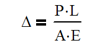
Where Δ is the deflection under load, P is the applied load, L is the length between the bottom of the head and the start of the fastener, A is the cross sectional area of the screw and E is Young’s modulus.
We cannot change P, A or E in most cases unless we add fasteners or change the size, so we need to change L. If we lengthen L, we increase the minute deflections allowable under the given preload.
Fasteners are not designed for bending loads. A fastener has a relatively small diameter in comparison to what is being joined. It is foolishness to design a fastener to take a bending load, but all so often bolts fail in this fashion. A telltale sign of this type of failure is seeing a large asymmetrical velvet section on the break.
The strength of a fastener comes from its area and not the area moment of inertia. As an engineer make your joints a combination of axial and shear loads. The formulas for calculating he stress are as follows:
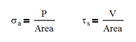
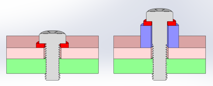
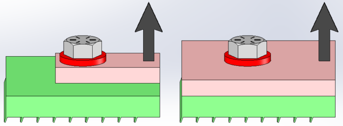
Yes, both are a function on the area! This is how we get maximum strength from the fastener. So let’s look at a classic example of a screw subject to bending loads. Quite simply, the figure on the left shows an upward force on the right side and the top material barely larger than the washer. This load will pry the parts apart and cause a slight slope to develop under the head of the screw. The slope with unevenly load the screw causing it to have higher tensile load on the side closet to the load, aka bending. To avoid this, change load on the fastener from a moment to one part of a couple. In the figure on the right, there is much more space on the opposite side of the load. The more space allowed, the more like a couple it is. The couple manifests itself as a compression load at point ‘A’ and a tension load at the bolt centerline. There are no hard and fast guidelines as to the proportions, but the further they are apart, and the closer the fastener is to the load, the better.
One thing to consider is the thickness of each part. If the top plate is too thin, it will deflect too much and you basically end up with the case on the left anyway.
It almost goes without saying that a fastener will fail prematurely if it is installed incorrectly. If the screw’s shaft isn’t visually perpendicular to the hole, it doesn’t have a good chance of being successful. There are usually several obvious causes to this:
Try to solve these problems first. If you have multiple fasteners in a joint, try to have both plates CNC cut (laser, plasma) so that they will lineup every time. If you are mating several surfaces in a joint, can these surfaces be held better in a welding process? Perhaps the entire joint needs to be machined after welding.
I will give you one glimmer of hope. This type of thing is already accounted for in testing standards. ASTM F606, a standard that governs fastener testing, requires a “wedge” test. If you imagine doing a standard tension test on a fastener, you would expect the bolt and nut to be on surfaces parallel to each other. This wedge test requires an angle to be put on the side of the part to be tested. These plates are not parallel anymore and the bolt will now have a bending component. The standard requires different angles based on the diameter of the screw. This should give you some relief that your fastening systems don’t have to be perfectly perpendicular to be successful.
This is where most failures occur. Since the analysis for both are the same, we will tackle them together. For general fasteners, those that aren’t a critical structural element, we like to stay below 50 percent of the proof strength. Examples of this are bolts that hold on covers, valves or other items that won’t damage the user or machine. In design, I like to be a little more conservative and look for a 5:1 design factor from hand calculations. This usually keeps me farther away from low preload issues without causing excessively larger or a high number of fasteners needed. Most bolts fall into this category.
The remaining fasteners fall into the, engineered fasteners category. An example of this is a rotation bearing with a crane or the gearbox that causes it to rotate. For fasteners like these, it would be best suited to aim no higher than 75 percent of the rated proof load. The reasoning behind this is that we do not want to go too low which forces us to use a larger bolts or higher grades. Also, we do not want to have a situation where the bolt is overloaded and be at a disadvantage due to stretching the bolt which in turn creates a propensity for it to loosen. If and when this occurs, it can cause another bolt near it to pick up the extra load. This is generally undesirable.
With fasteners, the tensile area is not equal to the area of the minor diameter. No matter where you take a section, you will find that the cross section will contain some thread and that area should be counted in your calculation. For example a ½” screw has a minor diameter of 0.4056 in leading to an area of 0.1292 in^2. However, when the thread is included, an area of 0.1419 in^2 is the tensile area. This is 9.8% more usable area.
The other thing to consider is that we are applying torque to a bolt and not directly applying a tensile load. This introduces data spread into our system that needs to be accounted for. Unfortunately, we need to introduce statistics into our calculations. Yeah, I don’t like it either, but we will keep it simple. But this spread is the main reason why we want to design to 75% of proof: some screws may be at 60% while others are at 95%. As long as we don’t get to 100%, the bolt won’t stretch and we will be good.
So torque and preload are related luckily by the following formula.
T = (K D P)/12
The value of K is the most difficult to estimate making a very simple equation complex. The general range is 0.10 for lubricated fasteners to 0.25 for rusted or hot dipped galvanized. Our goal is to make this constant very low and consistent. Good values for this are 0.12 to 0.15. The main way to accomplish both is with lubrication. Lubrication comes in a variety of forms
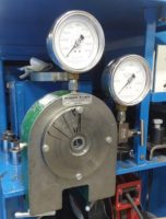
Bolt Tension Tester (above), Torque wrench calibrator (below)
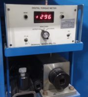
For example, we can take a 0.50” bolt and torque it to 64 ft-lb. When a k-factor of 0.13 is used, we should expect a preload of 11,815 lb. As we can imagine, the torque applied isn’t the same on every bolt and neither is the k-factor. To get good results, the first thing we need to do is make sure that every torque wrench is properly calibrated and has a set inspection schedule. Second, we need a sample of torqued bolts and their preload. To do this we will need a bolt tension tester. A screw and nut are coupled in the center hole and as they are tightened, a gauge will read the load on the fastener. Here are a couple notes:
So on to the long awaited statistics part of this. (See how I brought it up long before we got to it so that your blood pressure would lower.) The first thing that needs to be done is select a sample size. I recommend somewhere between 8 and 15 samples. I have made up data for 20 tests of a ½” fastener when torqued to 64 ft-lb. The first 10 samples are directly from the factory and have no additional lubrication added. Please note that this is an essentially uncontrolled lot and depending on the length of time and location it was stored could give us dramatically different information lot to lot. The second group of samples, also torqued to 64 ft-lb, had copper anti-seize applied to the threads before install.
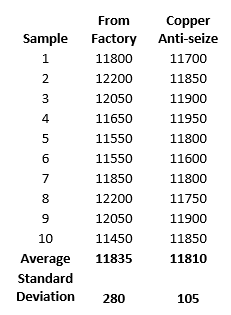
You can see that both samples average out to about the same amount, giving a k-factor in both groups of 0.13. But one group is clearly better than the other. The fasteners with copper anti-seize have a smaller range of data scatter and we see this from the standard deviation. If you remember the bell curve from your statistics class, you may recall that at one standard deviation, 68% of the samples will fall within that range. At two, it is 95% and at 3 it is 99.7%. (It’s ok if you didn’t remember, I remembered for you). So at 99.7% that is pretty close to 100%, we should use that as the base of our calculations.
So with the factory sample set, 99.7% of our fasteners should have a preload of 10995 lb. (77484 psi, 59 ft-lb) and 12675 lb. (89323 psi, 69 ft-lb). Good if you are using a grade 8, but overloaded if you are using a grade 5.
With the copper anti-seize sample set, 99.7% of our fasteners should have a preload of 11495 lb. (81007 psi, 62 ft-lb) and 12125 lb. (85447 psi, 66 ft-lb). This is a much more controlled data scatter, but still a little overloaded if you are using a grade 5. You might back off the torque a little, change to a larger fastener or switch to grade 8.
Statistics complete! Breathe now….
Depending on how critical your joint is, you may want to back it up with testing data. I recommend running a strain gauge test on the fasteners. It is difficult, but on larger bolts you can put strain gauges on bolts. There are two methods, but the more common one is drilling a hole in the bolt through head and centered on the shank and putting a specialized strain gauge in the hole. You will need to correlate the strain reading with the torque using a bolt tension tester before install.
From our statistical analysis above, you will want to read data from both under-torqued and over-torqued fasteners. The under-torqued fastener may be subject to fatigue loading in testing and an over-torqued may yield and loose preload. In either case, you will want to know what is happening and how to minimize the effects.
Finally, having real data on a fastener will allow you to perform fatigue analysis on the fastener. If there are multiple fasteners in your bolt pattern, you can then find out which one is the highest loaded. At that point, you can change the design to lessen or better distribute the load. You can also loosen or remove that bolt and run the test again. This will demonstrate what effect a loose fastener will have your our system.
Yes, bolts are still magic and we need to understand how they fail so that we can prevent failures in our designs. Knowing how to diagnose the five failure modes of fasteners is a valuable tool in and of itself. Being able to accurately predict bolt behavior, by calculations and statistical analysis, might just impress your manager. We all use fasteners in some way shape or form, so you need to know how to apply them properly.
In this video, Corey demonstrates using the and, or, not, latch and reset configurations in ladder logic.
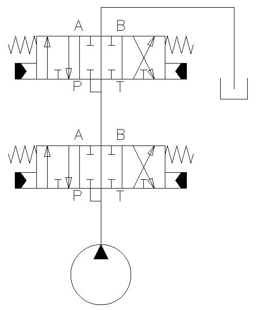
The log splitter that I own has two control valves on it. Both are tandem center and connected in series. I wanted to explain why this is a bad idea and should be avoided.
Tandem center directional control valves have the P and T ports connected in the center position. The way they are connected in series is to have the tank line from the first valve supplying the P port for the second valve. This repeats for as many valves as are in the series. This can cause increases or decreases in pressure and limits your supply of oil. Basically, the results are unpredictable.
Let me dive deeper.
I recently wrote an article on directional control valves. In it, I mentioned briefly what a tandem valve center is and how it is a bad thing if you have multiple valves connected in series. So, on our log splitter we have this bad situation. But really, in practice it isn’t such a big deal on this piece of equipment because it is rare that I am going to be operating the jib and the splitter mechanism at the same time. For this reason, I haven’t changed the valve configuration.
But I still want to illustrate what would happen if I did need to operate two (or more) functions at once.
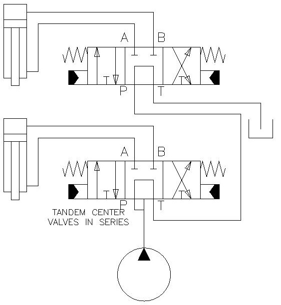
In this hydraulic system, I’ve got my pump putting out oil and the first stop is the valves. With both valves centered, oil is flowing through the first valve and coming out the tank line and going into the second valve and coming out the tank. Good so far.
If I shift the first valve so that P and A are connected, what I do is send oil from the B port of this valve back through the tank line which flows into the pressure line of the second line. Then if I decide to use the second valve, I am going to be using oil from the B port, not from the pump, to be doing the work. So the question you should be asking is, what is going on between the A and B ports?
You can probably already see the issue, but let me tell you why this would get a little wonky. Let’s say I am going to shift my valve so that P and A are connected. What I am doing is pressurizing a line causing a cylinder to retract. I have 3,000 PSI available from the pump and I have a two to one ratio on this cylinder. So that means my system pressure of 3,000 PSI is maintained and the cylinder multiplies the pressure to 6,000 PSI (2:1 ratio). Ouch! That is a problem!
What happens if I now grab the other valve and shift it so that pressure can build on the P port of the second valve? This could happen if I am trying to pull a stump out of the ground while trying to split at the same time.
I know highly unlikely, but theoretically it could happen and there are many other situations where you might need to operate two cylinders. Anyway, I can build up 6,000 PSI before the first cylinder stalls out.
So I have the ability to intensify pressure, even above system pressure, and create unwanted operation of the system. I doubt my tank port on my valve is rated for that. I also doubt that the hose or cylinder ports are rated for that. This leads to damage of components, line breakage or potential bodily harm. Small holes in hydraulic hoses can shoot oil out that can cut through skin. You definitely don’t what to get it in your blood stream.
Anyway, back to the issue at hand. So, there are many potential issues with pressure intensification. Remember that if only one handle is pulled, there is no issue, but if another valve is shifted, we can create high pressures or…
Our second problem exists if we operate the first valve the other way. I now put 3,000 PSI into my two to one ratio cylinder. With 3000 psi in, I am only getting out 1500 PSI out of the tank port. I have cut my available pressure in half! Furthermore, if the cylinder is doing any load lifting, I’m going to lose even more pressure.
So now if I activate another valve, let’s just say I am trying to lift a load on the jib. If that takes more than 1,500 PSI it’s just going to stall. If there is enough pressure to open the load holding valve, it may even fall. So that’s another problem with using tandem center valves in series: I don’t have enough pressure to do what I need to do.
With a system of two cylinders like the log splitter, there is only a finite volume of oil available. When I shift the valve on the first section, I will eventually either fully extend or retract the cylinder. At that point there is no oil available for the other valves.
If I continue to keep the valve shifted, I am going to blow over my relief valve and potentially overheat the oil. Even if I wanted to intensify the pressure, I could only do it for a few seconds or so. This is the third reason why we don’t want to use tandem centers with multiple valves.
These three hazards increase and intensify with each valve section added. If you are coordinated enough to control 4 sections, you may get very unpredictable pressures and unit performance. As good engineers, we need to avoid this possibility altogether though. Luckily, there is a readily available solution.
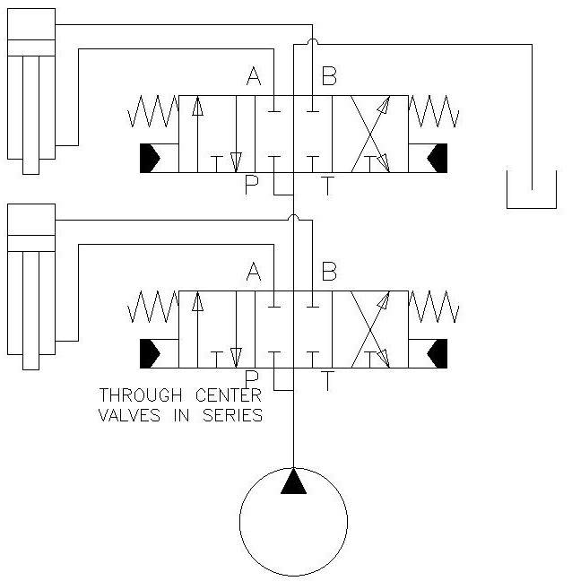
What we want is to have a through center configuration which allows me use fresh pump oil for each valve section. So, when I close off my pressure port by shifting a valve, oil is cut off to downstream valve sections, and pressure can build for me to do work. The oil returning from the valve section goes directly to the tank. This provides safe and predictable operation of my system.
The other thing through center configurations allow me to do is better control multiple functions. Before, with a tandem center, I would be taking the oil out of this cylinder and powering the next one and that works for a very short period of time. But what I can’t do with that is flow share of any kind. A through center valve will allow me to feather any valve and get the desired behaviors I want.
With open center valves like these, there are limitations for performance. For starters, when two or more functions are selected, the flow per function drops. Also, the lowest pressure function will get all of the oil first. If you want other valves to get oil, you will need to back off the lowest pressure function. If this is an issue, you can look into using pre-compensated and post-compensated valves. They are more expensive and complex, but their multifunction capabilities are unmatched. But for our log splitter, like I said, it is very rare that I would split and use the jib at the same time. I am just not that coordinated, and I really can’t think of a reason to do it in the first place. I’m just going to leave it alone and be aware of the hazard.
I hope this explains why you would not want to use a tandem center for multiple valves.
In conclusion, there are three things that can happen when using a tandem center valve in series
It avoid this, select a valve set that has a through center configuration. It will allow you to properly power many valve sections without these effects.
As I often design equipment that uses roller chain and sprockets, there are occasional failures. It is critical to identify the failure mode and eliminate the cause.
Overload, fatigue, rust and high speeds combined with small sprockets are the four main reasons roller chains fail. Overload and fatigue can be caused by galling, shock loading, misalignment or loads that are too high. A 10:1 safety factor is recommended. Rust is usually a sign of poor maintenance.
Let’s explore each one.
Having loads that are consistently too high will manifest itself as the pin holes enlarging leading to eventual tear out. The other cause is the pin breaking. Pins can break because of high shear loads, but also because of galling. Galling is the wearing of two parts on each other. Without proper lubrication, the pin can gall on the links and that leads to pin failure.
The loads applied for an overload condition are generally constant during use. If you notice that only one side of the plates is worn, look for misalignment. Misalignment will load one side of the plate more than the other.
To correct this, determine the cause of the overload. This may require performing calculations and making significant design changes. A safety factor of 10:1 is recommended for a new design.
If you are transmitting torque from one shaft to another, using larger sprockets can minimize the force. If you need to have a certain chain force, as in the case of linear motion, you will need to increase chain size or switch to a heavy duty version.
Inspect for chain misalignments; a laser pointer or level can be a huge help. Once corrected, tighten the bearing and sprocket set screws so that it doesn’t happen again. Finally, if this chain is worn replace the entire thing, not just a small section.
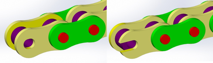
The symptom for a fatigue failure is different than we see in an overload condition. Rather than shearing the hole out like with overload, fatigue loads will crack perpendicular to the axis of the roller chain. The cause of this is the highest stress is on the material right at the quadrants perpendicular to the axis of motion.
If you can imagine, the stress flow increases around the sides of the hole. But directly before and after the hole, the stresses are fairly low. Having a high cyclical load starts ‘cold working’ the material in these high stress concentrations until a crack forms. Once the crack has started, it is only a matter of time before the link plates will fail.
To resolve this cause of failure, find out where the large cyclical load is coming from.
With electric motors, there is less that can be done to improve the dynamic effects on the system. Your only actions here may be to enlarge the chain size or sprocket size or add a flywheel.
Another option that is out there, but I am reluctant to recommend, is putting a second chain tensioner on the high tension side. So we all want to put a tensioner on the low tension side because it can be designed to be very small since there isn’t much tension on it. Adding one to the high tension side is more difficult because these components will have to be much more massive and often requires the use of very heavy springs or a cylinder under constant pressure.
Putting a tensioner on the high side will smooth out the cyclical component which will prevent fatigue. For some systems, this may be a last ditch effort.
If you have had a fatigue failure in your system, please check the calculations. There may be some flaw in the design. Again, lowering the chain force by using larger diameter sprockets will help. Be sure to replace the entire chain.
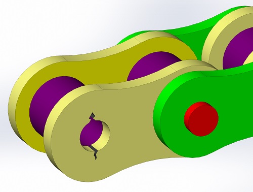
This one is way too common, but there are several different kinds of failure modes. Link plates that crack in arcs are a symptom of exposure to an acid or other caustic substance. This should not be confused with fatigue failure.
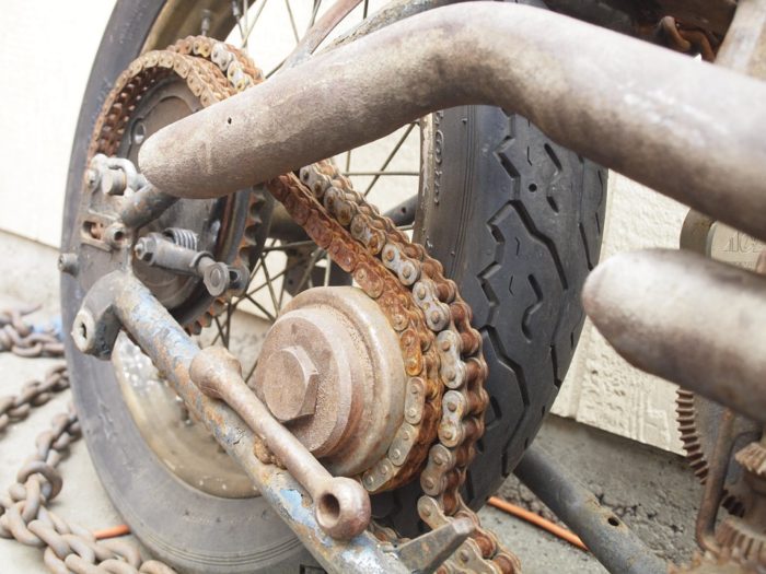
Another symptom of corrosion is surface pitting and this is generally noticed on the sides of the links. Rust is by far the most likely to be seen in industrial and mobile settings. You will probably notice the red color first, but another symptom is kinks in the chain. Kinks form when the chain isn’t exercised and the chain links, pin and sleeve rust together. It is most noticeable when the chain is rusted together when engaged on the radius of the sprocket.
To prevent corrosion, you will need to remove the chain from the environment. Sometimes the corrosive environment may be created from your lubricant. Avoid lubricants that contain water, acids or alkalines.
If you cannot separate the chain from the environment, maybe switching to serpentine or v-belts would be a better solution. They are often more chemical resistant. To prevent rust, proper lubrication must be done more often and before storage.
Any rotating piece of machinery has a critical speed; roller chains are no exception. The critical speed is the chain velocity where uncontrolled vibrations will occur. These vibrations are always undesirable. The difficult thing is that the speed is very difficult to calculate and often gets overlooked.
The good news is that if you find your machine operating at the critical speed, a change of 10% can make a huge difference. Critical speed is the function of length of chain span, tension in the chain (be sure to check high and low tension sides) and chain speed just to name a few. For those of you who play guitar, this is the same concept. We can alternate tension, string size and string length to get different frequencies.
Just like with buckling, the best solution may be to add supports for the chain so that it can’t move. Adding a support requires the chain to vibrate at the next highest natural frequency. Using the guitar analogy this is adding the harmonics of (sequentially) the 12th, 7th and 5th fret.
Using a chain tensioner can sometimes solve this problem as well, by adding more tension. Using a lighter weight chain or switching to V-belts can also help.
So how do I prevent chains from causing problems? The key is inspection and preventative maintenance.
Inspection is critical for the longevity of your chain and sprocket system. Inspections should be done daily and semi-annually or annually depending on the operating environment. I would lean more towards semi-annually if your system is outside, in corrosive environments or if downtime has a severe impact on production. It is far easier and less costly to schedule downtime than have it forced upon you.
Daily inspections should be designed to be quick and look only for major problems. Some items should be done while running the machine and others while it is off. Be sure to lock the machine out while inspecting! Here are some questions to think about when determining your daily inspection list.
All these inspections can be done in a relatively short amount of time. Having a daily checklist can prevent large amounts of machine downtime. If the inspection process is simple and quick enough, the operators will be more likely to complete the process without much coercion. Now, onto the big inspection.
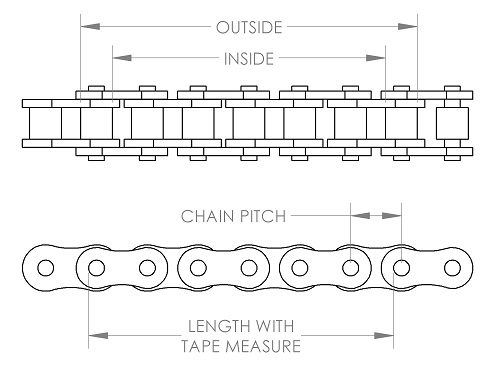
Initial Length = Chain Pitch x number of links
Most chains come from the manufacturer pre-lubricated. Steps should be taken to keep them from coming in contact with dirt. Don’t lay chains on the floor, that’s where the dirt is. Lay down some fresh plastic sheets instead. Those sheets are a whole lot cheaper than the chain.
When cleaning the chain, be sure to use an approved cleaner for use on chains. Do not use acid cleaners, liquid alkalines, gasoline or benzene as they have adverse effects on the steel chains. Kerosene is a good cleaner, but check with your company’s policies for using it.
There are many spray-on chain cleaners that work really well too. Just be sure that they are safe for use around O-rings. Chances are, you will have an O-ring near where you are spraying.
I recommend using a toothbrush or a chain brush to get particles off the chain. Wipe the dirt off the chain with a clean rag (it may take many rags to do this). For dirty chains, spray and repeat the cleaning process. Some people recommend a final rinse with water, but I don’t recommend that. Water is the enemy and there is enough of it in the air. We don’t need to look for ways to make our chain rust.
The next step is to dry the chain. You can do this by letting it sit out.
Finally, lubricate the chain. Select a lubricant that is safe on O-rings. You also will want to consider a no-fling formula. Nobody likes having oil flung at them when the machine starts up. It creates a mess on any surface in its path and ticks off the company environmental guys.
If a chain has a significant amount of rust on it, consider soaking the chain in the lubricant for a few hours. Hang it up so that it can drip into a bucket. Your chain will be well oiled around the pins after that. Be sure to resist the temptation to wipe the chain dry. One final thought on selecting a lubricant: be sure that it does not contain water. There are many, even popular name brands, that contain water. Don’t use those. The water will eventually do what it is meant to do to steel: make it rust.
Roller Chains and Sprockets are great systems to transmit power because of their high efficiency and robust design. If you use this criteria to design a chain system and maintain it, your system should have a long working life.
Directional control valves are a splendid thing. These hydraulic valves allow us to control the direction of cylinders, hydraulic motors, and any number of other actuators. Valves generally fall into one of three categories:
A monoblock valve is a single piece valve body that is usually made of cast steel. It can have between 1 and 7 (sometimes more) valve sections. Each section has a round bar called a spool in it that slides linearly in a hole that is bored in the body. The body has an inlet side and an outlet side.
Often times, there is a relief port built into the inlet and on most outlets has the option for ‘power beyond‘. The spool has numerous cuts in it that not only control the direction of flow, but also the speed of the flow out and often back into the valve. Incredibly complex things can be done with valve spools and it would take a lifetime to study and understand all of it.
A sectional valve is like a monoblock with the major difference being that each valve is its own unique section. If two directional control valves were required, the valve assembly would have 4 sections. They would be Inlet / Section 1 / Section 2 / Outlet.
Generally speaking, there are some nifty options available in a sectional valve that are not available in a monoblock. Some options are, load sense, compensation (pre or post spool) and anti-cavitation.
Cartridge valves are an entirely different monster. These valves consist of two components: a cartridge and a manifold. The manifold has one cavity (sometimes more) and holes are machined to allow oil to flow to and from the cavity to work ports where hydraulic adapters are connected. These manifolds are usually made out of aluminum and can be customized to ridiculously complex designs often integrating dozens of individual cartridges.
Manifolds can also be made to be stackable using ‘DO’ (sometimes referred to as ISO) interface. Interfaces D03, D05 and D08 are the most popular. (Yes it is really D ‘zero’, don’t get me started.)
The cartridges themselves range from simple to quite complex. You can get almost any type of valve in a cartridge form. They are also able to handle very large flows upwards of 100 gpm although you might have to have a smaller valve piloting a larger one.
When you are dealing with directional control cartridge valves, your options are limited. Many solenoid operated valves don’t have mechanical overrides. Because of their versatility, cartridge valves can be seen used in most hydraulic systems and often in monoblock and sectional valves.
A single valve section is classified by the number of ways and positions they have. Most directional control valves are four-way, three position. What that means it that is that there are four ports or ways into or out of the valve. Positions is the number of different configurations you can put that spool into.
Other classifications are: valve activation and overrides, detent (stays in current position), switches and center position configuration. For example, we might classify a valve as 4 position, 3 way, open center, pilot operated with manual overrides. Yes, that is a mouthful, but each phrase gives you pertinent information about the valve. From this, you could almost recreate the schematic in your head. After all, that is the idea.
So, let’s talk about what activates these directional control valves. Common methods are:
Looking at the figure above each one of the valves is 3 position, 4 way. The positions are shown as left activation, center, and right. The center position is commonly referred to as the first position. If you have a two or three position valve, the first position will be the resting position.
The ways of the port are usually numbered or represented with the letters P, T, A, and B. P is for the pressure line, T returns the oil to the tank or reservoir, and A and B are the work ports, where you would connect a cylinder or motor.
If I shift the valve to the left, the furthest right part is now going to be in the middle where it has access to the ports. In the cases shown above, the P and B would connect and the A and T as well. If I shift the valve right, P and A would be connected.
Note here that the valves have arrows on them and those arrows can have heads on both sides. These are important because trying to have fluid flow the opposite way could cause the valve to close or become unstable.
A practical application is to have the work ports connected to a cylinder with the A port causing it to extend. Shifting to the right allows the cylinder to extend giving a well-defined path between all the ports.
Reversing direction swaps the work ports and the cylinder will extend. In the case of most valves, when I release the controls, the spool is going to stop movement and spring back to center and stay there.
There are so many option here, but we are only going to discuss the six most common. They are represented above and are nowhere near all the combinations. In fact, I just recently needed to specify a center position where P and A were blocked, but B and T were connected. I know, weird but necessary.
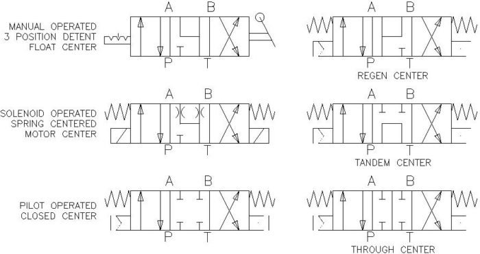
A tandem center lends itself well to a single valve or a valve at the end of a series of valves. In this center, A and B are blocked and P and T are connected. This allows the constant flow of oil through the valve which is perfect for a gear pump.
The problem with tandem center valves is you can get some pretty weird characteristics if you stack multiple valves like these together. My log splitter has two tandem center valves for the splitting and the jib. It is not an issue because I don’t use both valves at the same time, but still, don’t do this. I will be writing a separate article on this later.
This is where everything is closed and there is no oil flowing anywhere. This is good for holding a cylinder up, but there will be leakage over time. Be very careful and do not use this with something that is moving very fast like a motor.
If you have very high flow rates and you stop it; you are going to have a large water hammer effect on this. If you think about your home’s plumbing, when you shut off a faucet, you can sometimes here the banging of pipes for a second. This is a water hammer. The fluid has momentum that suddenly has nowhere to go.
At your house, the water pressure is only 50 to 60 psi and a flow of 5 gpm. Think of a hydraulic system of 3000 psi and 10 gpm. Please know your system and only choose this for applications where there is not much flow.
This one is very common on closed center hydraulics. This is where the pressure port would be closed and then A and B go to Tank. This prevents any pressure from building up in a work port line.
If this valve was activating a motor, the motor would freely spin until it stopped. However, this would not hold any pressure, so using it to hold a load on a cylinder would not work.
If you choose this option, you would need an alternative method to hold the load like a pilot operated check or counterbalance valve.
Motor spools are the middle ground between closed center and flow center. What it allows it to do is to bleed off the pressure in the A and B ports quickly and predictably. When using a motor, the closed center builds up pressure instantaneously, and a float center doesn’t build any pressure allowing for a long wind down.
The motor spool (yes, it is named after the function it does) builds up some pressure and this causes the motor to stop quickly and smoothly. If you are holding a load on a cylinder, you will still need to have a counterbalance valve or PO check in between your valve and the cylinder.
This is short for a regenerative circuit. A regen circuit is very rarely used. The center position has the P, A, and B ports tied together, and the Tank is blocked. So, if I have a cylinder connected to the A and B port and I pressurize both the A and B ports, most people think nothing happens. That is not true.
What actually happens is the oil pressurizes both sides of the cylinder equally, but the cylinders do not have equal areas. The bore side has a larger area causing a force imbalance. So what will actually happen is the rod will extend very quickly because it only has to move the amount of oil that the rod takes up. This is only the area of the rod. Since you only are moving the area of the rod, you only have the force equal to the rod area. The benefit is that it moves really fast.
Take note that the fluid moving through the center is the flow from the pressure plus the flow from port B. (There is flow from P and B to A). You may need to specify a larger valve or larger work ports to get the operating characteristic you want. This center position gets is name because the flow from port B is reused before going back to the reservoir.
There is a lot of other ways to do this, but a regen center is one of those ways. It is great if you need something to go out quickly, like a log splitter. About the only practical application for this is a cylinder where some clamping force is always needed. In the relaxed state, it clamps with only the force of the rod. If you change the valve position it would give full pressure or retract the cylinder.
As I mentioned before with a Tandem center you don’t want to stack a whole bunch of these together because it causes undesired consequences. Instead, when you have a series of valves, you must use a through center. This allows you to get consistent pressure and flow when multiple valves are activated simultaneously.
You can see that both of these valves are tied to directly to your pressure line. When you shift the valve, the pressure cannot flow to the next valve section building up pressure that can be used in the active section. If this is a proportional valve, only part of the flow will be blocked, leaving the other sections to perform work as needed.
Another benefit of the through section is called power beyond. This allows the flow to power another valve or valves downstream. This is great if you have several different control areas on your machine.
One thing to note is that with each valve in the system, the valves start to have priority. Any valve can take all the available flow, but if multiple different valves are activated, the ones further from the pump will have lower priority. This can be both a detriment and an advantage.
For example, if I had a function that could only be active when nothing else was, I could put this last. This way, it would shut off whenever another function is activated.
In conclusion, directional valves are both complex and simple. They are easy to understand, but designing a system that works well is very complex. After reading this article, you should be able to: