Recent Posts

How to Easily Calculate Gear Ratios in Planetary Systems

Planetary gear systems can be intimidating to understand. There are so many types of motions and reductions possible that it can be overwhelming.

The motion of planetary gear systems is expressed clearly in the Plantetary Train Equation: -S/R = (ωra)/(ωsa). Once this is known, the speeds of the carrier arm, sun and/or ring can be calculated. Multiple series of planetary gear systems can be used to get multiple speeds and directions.

Planetary gear systems are used everywhere. Some examples are:

  • Automatic transmissions
  • Internal bicycle gearboxes
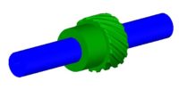
  • Pencil sharpeners (I bet you didn’t see this one coming)
  • Winches
  • Hand drills
  • Camera lens focusing
  • Truck differentials

Planetary gear systems are primarily used for one or more of the following reasons:

  1. Reverse Motion
  2. Transmit more torque than one gear set will allow
  3. High reduction rates
  4. Use with other sets for multiple speeds
  5. Input and output need to be coaxial

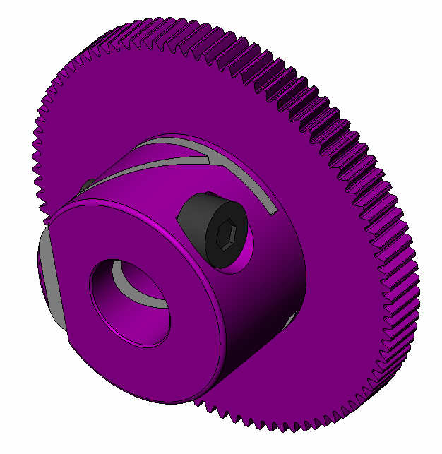
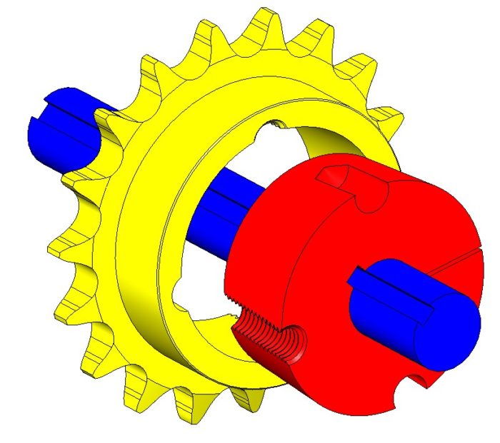
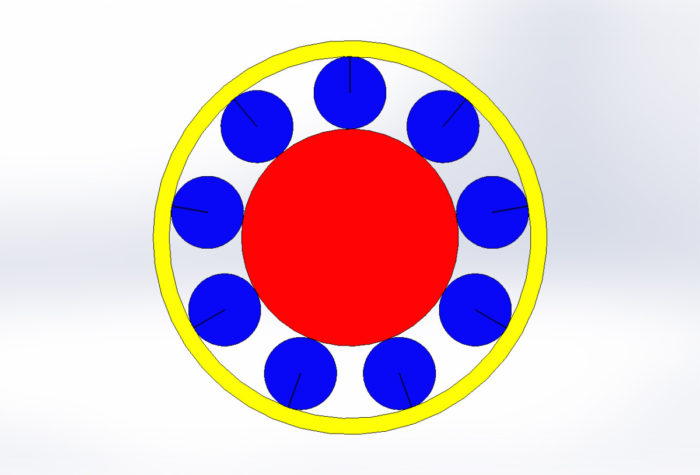
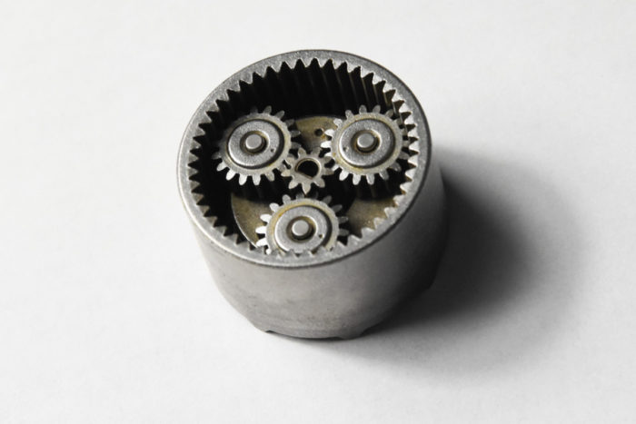
Planetary Gear System Components

Planetary gears sets have 4 major components: sun, planet(s), ring and the carrier or arm. The planets are assembled onto the arm. The planets mesh with the sun and the arm rotates around and on the same center line of the sun. The planets also mesh with the ring gear.

Generally, either the arm, ring or sun will be fixed in rotation so predicatable motion will occur. In rare cases, the input and output are linked together so that there is no relative motion between the sun, ring and planets. Automobile transmissions use multiple systems and sometimes the sun and the ring will turn to provide power to the arm.

Sizing the Gears

It is important to size each of the gears so that they fit properly. There are two simple formulas that will help you choose the right gears.

First off, all of the gears must have the same diametric pitch in order to mesh. Next, the following equation will relate the number of teeth on the sun, ring and planet. The variables could also represent the pitch circle of the gears, but most use the number of teeth to quickly evaluate if the meshing will work.

S – Sun, R – Ring, P – Planet, A – Arm

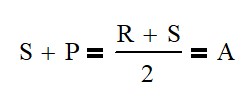
For example, if your sun gear needs 17.5 teeth from the calculation above, your system won’t work because teeth always need to be an integer. This is a little more difficult to see when using the pitch circle of the gear.

Calculating the Number of Planets

One of the main reasons to use planetary gear systems is to increase total torque. Every planet in the system adds a new path for force to flow. So where you may be limited by tooth strength, adding planets will allow you transmit the torque through multiple teeth. Genius!

Another benefit of having at least 2 planets is that it will balance the radial forces (force pushing the gears apart) on the shafts leading to smaller shaft designs.

A system where S = 15, R = 45 can only support 5 planets.

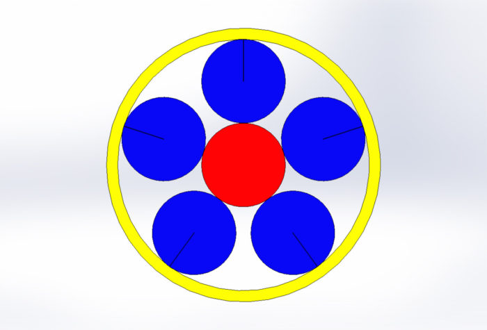
The number of planets for an system is limited first by the space available for the planets to occupy. A system with a small sun and large ring will have less planets even though there is more space available than a system where the ring is only 50% larger than the sun.

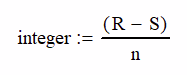
The other limiting factor is the teeth meshing properly. This can be determined by the following equation.

n is the number of
planetary gears

The result of this equation must be an integer for proper meshing.

A system where S = 27, R = 45 can support 9 planets.

The top example has an R – S of 30 where there could be 1, 2, 3, 5, 6, etc. planets We find out that the spacial constraint is 5 planets.

Similarly, the second example has a R – S value of 18 leading to 1, 2, 3, 6, 9 and 18 planets. This design can support 9 planets.

Calculating Motion of the Components

Generally speaking, we care about the motion of the carrier arm, the sun and the ring. Usually, one of those will be fixed, but there are many times that they may all be moving. Automatic car transmissions are a great example of this. The following equation relates all the components together.

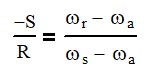
Where S is the number of teeth on the Sun, R is the teeth on the Ring, ωr is the speed of the ring (usually rpm), ωa is the speed of the arm and ωs is the speed of the sun.

For example if we take the second example up there with R = 45, S = 27, P = 9 we can find out the relationships:

FixedInput (1 rev)Output (rev)
RingSunArm 0.38
RingArmSun 2.67
SunArmRing 1.60
SunRingArm 0.62
ArmRingSun -1.66
ArmSunRing -0.60

Multiple Planetary Sets

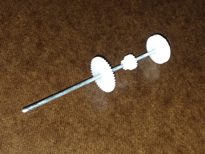
You can also apply this in steps to get multiple reductions. For example consider the reduction a drill I recently disassembled. (R – 45, S – 9, P – 18) There are two stages in the reduction, where the arm on the first section drives the sun on the next section.

The carrier of Section 1 drives the sun of Section 2

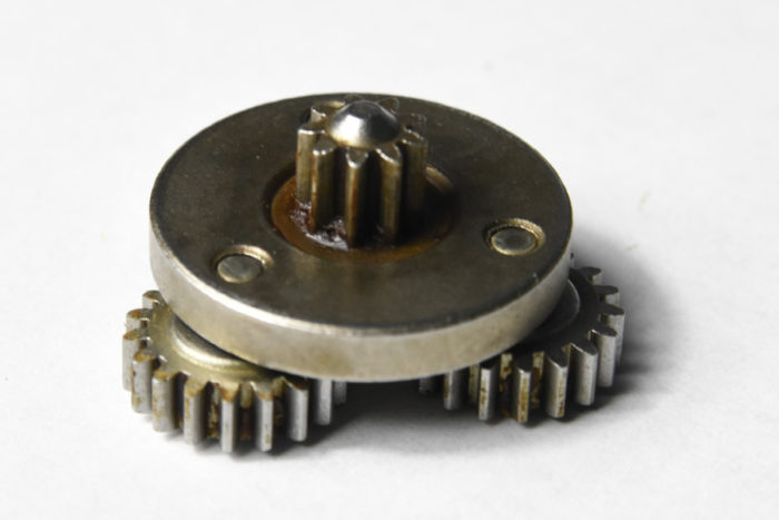
In the drill, the ring is held fixed except when the torque is greater than the desired setting. At this point, the ring will slip and no output motion will occur.

To calculate the output speed, we will need to use the equations below. It is the universal equation used twice and the speed of the first section’s arm is set equal to the second section’s sun

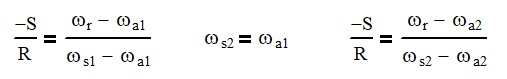
Since the gears have the same number of teeth in the first and second sections, we will have the same reduction in each section which is 1 : 1/6 (input/output) or 6 input revolutions to 1 output revolution. When both sections are combined the ratio multiplies to 1 : 1 / 36 or 36 : 1. Gearbox ratios are commonly referred to as input to output revolutions.
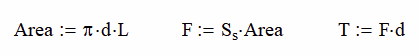
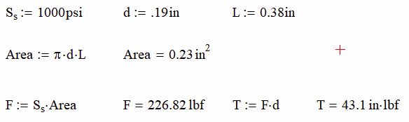
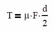
Assembled Section 1 side of planetary gearbox

Calculating Torque

This 36:1 ratio gives a tremendous mechanical advantage because it allows the use of a small and fast electric motor to have tremendous torque on the output.

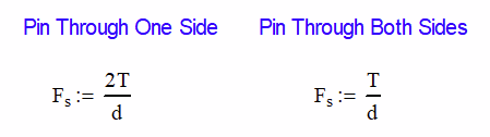
The ratio of input to output (N) is 36:1 for the drill. The relationship of speed and torque can be calculated using the following equations:

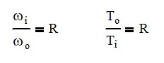
As in normal gear equations, as speed decreases, the torque increases. With normal spur gears, you can only transmit torque through one set of meshing teeth. However, you can multiply the available torque by the number of planets in the system. This is provided that the gears and other components involved have a high level of precision.

Conclusion

Planetary gear systems can be intimidating, especially if there are multiple sets. Break them down into smaller sets and tackle them one at a time. Count all the gear teeth and then run the equations to confirm that you counted correctly. These systems can be simplified greatly with just a little analysis.

For Further Study

If you want know more about gear system designs, read the article below. To calculate the torque that a gear can transmit, the section on gear tooth forces begins about half way through.

How to Use Gears – What You Really Need to Know

How to Achieve High Ratio Planetary Gearboxs

All Gear Articles and Videos

Introduction to Planetary Gears

How to Attach Gears, Sprockets and Pulleys to Shafts

Unlike the Lego gears and shafts shown below most motors have perfectly round shafts. This makes attaching gears, pulleys and sprockets difficult.

The main methods of attaching gears to shafts are adhesives, press-fitting, cross drilled holes, compression, set screws, keyways, involute splines and taper lock bushings. Most industrial applications will use keyways and / or set screws. While adhesives and press fitting are usually done on low torque or hobby applications.

Let’s investigate each method weighing the pros and cons. I will also be using the terms; gears, pulleys, sprockets and cams, interchangeably as this article address the how the device is mounted, not what it does.

Adhesives

Adhesives are mostly used in hobby applications with plastic gearing. Not only because plastic gears cannot handle much torque, but also because the shaft sizes remain small in diameter.

Image Courtesy of Creative Commons

As the shaft diameter increases the relative strength of the glue joint and the shaft strength are equal at roughly 3/16″ (5 mm) when using a conservative glue strength of 1000 psi (7 N/mm) and a shaft of C1018 steel (54 ksi, 370 MPa).

Conclusion: using adhesives is a good choice for small shafts

As mentioned, most adhesive manufacturers will advertise a lap shear strength of at least 1000 psi and some as high as 3000+ psi. A lap shear test is done by having two long skinny bars attached together with the glue over a measurable area. The ends of the bars are pulled apart until failure. The force is divided by the area and the result is the lap shear strength.

I usually design around the low number of advertised shear strength here as there are many factors at play which can lower the actual strength. Among these are surface preparation, surface area application, temperature and humidity.

Before applying the adhesive, you will need to rough up the surfaces of the pulley and the shaft with some sand paper (~200 – 300 grit) or a fine file. This will give the glue small nicks to grab on to. You will then want to clean and degrease with a cleanser and then dry fully. I like to use brake cleaner usually because I have it around.

To figure out if your application will withstand the applied torque. Use the following formulas.

Where Area is the surface area between the shaft and the pulley, d is the shaft diameter, L is the overlap length for the shaft and pulley, F is the internal shear force between the shaft and pulley, Ss is the shear strength of the adhesive, and T is the applied (or maximum torque).

Using an average adhesive shear strength of 1000 psi, a diameter of 0.19 in, and overlap length of 0.38 in, we can find that our maximum Torque is 43.1 in lb.

There are three main cons of using the adhesive method to join a pulley to a shaft

  • The torque is limited by the diameter and adhesive strength as already mentioned
  • There is the ability to have the shaft and pulley out of center and / or perpendicular. This can be minimized by the tolerance between the two, but not so tight that you would wipe off all the glue.
  • There is no way to adjust or replace the components without the possibility of damaging 1 or both components. Having adjustment is important and this method doesn’t allow for it at all.

Joining Shafts Together? Check out our guide to shaft couplers.

Press-Fitting

Press-fitting is a tried and true method of attaching gears to shafts. It has been in use in the railroad industry as a method to save money when wheel assemblies wear out or become out of round.

The main wheel weldment has a precisely machined diameter and then a thin band of hardened steel is applied around it. The band or “tire” is actually smaller than the machined surface. This allows the inexpensive band to be replaced from time to time instead of the whole wheel assembly.

The following video shows how the tire is removed from the wheel by using heat. The band will expand in diameter as the temperature rises. The wheel (inner diameter) will stay roughly the same size because it has a lot more mass and will radiate heat away faster.

At this point, the band can be pried off and a new one installed by the same method.

Because there is no mechanical lock on this, it is 100% based on friction and it can slip. Measuring and determining the press fit is difficult and assumptions usually need to be made.

Super Slow Free Online Shaft Press Fit Calculator or Go Pro

Where Pr is the pressure between the surfaces, δ is the amount of press fit, d is the shaft diameter, do is the outer diameter of the hub or gear, di is the inner diameter of the shaft (if hollow), μ is the coefficient of friction between the materials and E and ν are the Young’s Modulus and Poisson’s Ratio of the materials.

Press fit gears on a shaft

Heating up the material will increase the diameter; therefore, decreasing the amount of press fit, δ. This make the gear easier to get on or off, but the end result the same once it cools.

If doing this at home with plastic gears. Try heating them up in the oven at about 175° to 200° (79°C to 93°C) and then sliding them on the shaft.

This method is adjustable, but not easily and you may need to disassemble multiple components so that heat does not destroy them.

Cross Drilled Holes

Drilling a hole through both the gear hub and the shaft is a great way to get a lot of torque. It also prevents the shaft from being overloaded because the pin will shear (break) if the torque is too much. There are three main types of pins to use in this application listed below from weakest to strongest.

Cross Drilled Hole with Roll (Spring) Pin
  • Roll (spring or slotted) Pins – These are flat bars that have been rolled to a round shape. They tend to spring open (hence spring pins) allowing enough of a press fit so that the pin won’t slip out. I recommend these over the other two options.
  • Shear Pins – These pins are solid and have a notch at the midpoint where the pin is designed to fail at a specific force. It is important to get a pin where the notch will be at the same plane as the shaft diameter.
  • Dowel Pins – These are just high strength solid pins. If your hole is too big, you will probably have to glue these in place (shear pins too). If your application reverses direction or load, you can encourage the glue to fail prematurely and the pin to fall out.

Each of the pins will have an advertised breaking strength and you can select the diameter and type based on the equations below. Fs is the shear force, T is the applied torque and d is the shaft diameter.

This method gives you lots of capacity to handle more torque, but is still doesn’t give any adjustment once the hole is drilled. If you mess up too many times, the shaft will look like Swiss Cheese.

On major benefit is that nearly anyone can make this joint. All you need is a drill, drill bits and a hammer. I recommend drilling a smaller diameter 1/16 – 3/32 first and check your alignment with a toothpick. If it is good, drill it out to the diameter you want. If not, rotate to another part of the shaft and try again.

Compression Hubs

While not a common method of attaching gears to shafts, it is available. Once the gear is slid over the shaft, the set screw is tightened and friction will carry the torque. The coefficient can be reduced inadvertently due to oily shafts or the use of anti-seize. It is best to use dissimilar metals when using this method.

Compression Style Gear

The cost of making the reliefs in the components makes this type method cost prohibitive in most cases.

Just avoid this type of joint!

Set Screws

The set screw (only) method of attaching to a shaft is very common with timing pulleys, gears and sprockets.

Typical Set Screw Timing Pulley

It is difficult to determine what kind of torque you can get out of a coupling like this. The result can vary wildly because of friction coefficient, applied torque, lubrication of the threads and set screw type. The basic equation is as follows:

Where T is the output torque, μ is the coefficient of friction, F is the normal force from one setscrew and d is the daft diameter.

Most people just tighten the set screw as much as possible. As long as the pulley doesn’t slip from excessive torque, everything will be all right. However when it does, you will quickly wear a groove into the shaft. This makes your shaft diameter smaller; thus reducing the maximum torque you can achieve.

The main benefit is that this method is 100% adjustable for rotation to the shaft and along its length. Generally, this method is only available with shaft sizes 1/2″ (13mm) or less.

Keyways

For most industrial applications the standard is keyed shafts.  By far any off the shelf gear will be available in a variety of bores sized with keys slots.  You can also buy them with unfinished bores and cut your own keyway if you like.

When selecting a bore size, make sure that you aren’t selecting a shaft that is too big for the for the gear.  Recently, I had a system that used a 10-tooth sprocket on a 1” shaft.  The system had some pressure spikes in it at startup and actually cracked the sprocket in half. 

It was able to do this so easily because the material between the outside of the hub and the keyway was only 1/8” thick.  We were able to double that to ¼ by adding one tooth. This is a situation where an involute spline would be a better choice (more on that later).

Most gears are held from sliding on the shaft with just one or two set screws.  Generally, one screw will be on the key and the other will be 90° to it and press against the shaft.  For spur gears, this is adequate, but for helical gears, there needs to be more of a positive engagement on the shaft to account for the side load.  Possible solutions are thrust bearings, tapered roller bearings or snap rings.

When in doubt, go with a keyed shaft.

Involute Splines

Involute splines are structurally better than keyways for transmitting high torques. Instead of one large key, we have many smaller keyways that evenly distribute the stress around the outside of the shaft better.

Image courtesy of Worthington Ag Parts

This can be a good and bad thing. It is good because the shaft won’t break as easily, but bad in the way that there is no mechanism that can safely fail if too much torque is transmitted.

An involute is the curve that is made when a string is wrapped around a cylinder and then the end of the string is traced as it is unwound. This is profile of the sides of each tooth on the spline.

The pros of this connection method is that large torques can be transmitted with ease and it is adjustable along the length of the shaft and can be oriented at many angles to the shaft. There are several cons including:

  • A set screw may still be needed
  • There is no fail-safe mechanism like a key to prevent too much torque from being transmitted
  • It is super expensive

Best Guide to Understanding SAE Shafts and Mounting Flanges

Taper lock bushings

Taper lock bushings aren’t a new method of attaching to a shaft; they still use a key. But they are a different way to mount the sprocket to the shaft. Instead of 2 main parts, we now have 3. The sprocket, the shaft and the bushing.

Typical Tapered Lock Bushing

In the figure above, the red bushing will slide onto the shaft in the desired position. The sprocket will then be slid over the bushing until snug. Set screws will be inserted at the top and bottom locations. As the set screws are tightened, the taper will force the bearing gap (on right) shut and lock on the shaft.

There are three main benefits of this design:

  1. Low profile
  2. The bushing can be removed by inserting the set screw into the hole on the left and screwing it in.
  3. No anti-seize is required! This is the one application where the bushing can be removed without the use of anti-seize. This makes it perfect for environments where anti-seize may be detrimental. The food industry comes to mind here.

Conclusion

There are many different methods of attaching gears, sprockets, cams and pulleys to shafts. Some, like adhesives and press fitting, are designed more for hobby applications. Others are clearly meant to survive out in the real world, like keyed shafts, taper bushings and involute splines.

FREE Hydraulic Hose Size, Pressure Drop and Calculator

Never guess again what hose size to use! Automatically the proper hose size for any application. Simply input a few measurable variables and click Calculate.

This calculator adjusts for oil type and temperature. See how your hoses work in hot or cold temperatures!

Want to Save Your Data for Future Use? Go Pro Today!

Oil Type Equivalent Roughness, ε (ft)
(0.0001 – 0.00015)
Operating
Temp °F
Density (lb/gal)
Flow, Q (gpm) Kinematic Viscosity (cS)
Length, L (ft) Dynamic Viscosity (cP)
Hose Size
(in)
Hose Area
(in^2)
Velocity
(ft/s)
Reynolds
Number
Relative
Roughness
Friction
Coefficient
Pressure
Drop (psi)
Power
(hp)
0.13
0.01
0.00
nan
0.000000
0.050
0
0.0
0.19
0.03
0.00
nan
0.000000
0.050
0
0.0
0.25
0.05
0.00
nan
0.000000
0.050
0
0.0
0.31
0.08
0.00
nan
0.000000
0.050
0
0.0
0.38
0.11
0.00
nan
0.000000
0.050
0
0.0
0.50
0.20
0.00
nan
0.000000
0.050
0
0.0
0.63
0.31
0.00
nan
0.000000
0.050
0
0.0
0.75
0.44
0.00
nan
0.000000
0.050
0
0.0
1.00
0.79
0.00
nan
0.000000
0.050
0
0.0
1.25
1.23
0.00
nan
0.000000
0.050
0
0.0
1.50
1.77
0.00
nan
0.000000
0.050
0
0.0
2.00
3.14
0.00
nan
0.000000
0.050
0
0.0
Notes:
1. Only good for fluid flow on earth.
2. Viscosities are based on generic empirical data and may not coincide to specific manufacturers formulas.
3. Target operating temperatures should be between 104°F and 120°F.
4. Viscosities are only accurate between 100°F and 212°F. Care should be taken for sizing hoses for use outside of this temperature range.
Suction Line: <5ft/sec
Return: Line: <10ft/sec, <2000 Reynolds
Pressure Line: <20ft/sec, <3000 Reynolds
Not Recommended: >20 ft/sec, >3000 Reynolds

Top Life Lessons Learned from My Engineering Career (Part 1)

Even though my engineering career is far from over, I wanted to look back and reflect. I realized that midway through my career is probably the right point to do this because if I wait too long, I’m sure to forget many of the early lessons learned.

So far in my career, there have been many lessons learned both personally and professionally. I wanted to share a few that are universally applicable. Just to give some background into my life, I have had a very rewarding career as a mechanical engineer so far. Here are a few highlights of my journey.

  • 2002 – Graduated from Baylor University – One of seven graduating engineers (28 total) with a job already (post 9/11 recession). Got married three months later. Laid off five weeks after that.
  • 2003 – Finally got an engineering job – Whoo Hoo! Only 46 weeks after getting laid off. My part time job as a snow cone engineer finally paid off!
  • 2004 – My career really took off and I was advancing quickly gaining skills and knowledge. The sky’s the limit!
  • 2007 – Kiddo #1 was born on Friday the 13th of April.
  • Fall 2008 – Expecting Kiddo #2, we decided to move from Texas to be closer to family in PA, so we moved to North Carolina for a new career opportunity. Career blossoms.
  • 2009 – Kiddo #2 was born and passed away 4 months later. We realized how blessed we were by the support of our church family. We reassessed our lives and dove deeper into our faith.
  • 2010 & 2014 – Kiddos #3 and #4 born. (Yes, I sometimes call them by their number. Who can remember names?)
  • Christmas 2017 – After being burnt out at work, I decided to take three weeks off to reassess my career path. Returned with the following dream.
  • April 2018 – Left my successful career and stable job to start my own design firm, Rasmussen Designs PLLC, with the goal of not having to go back to corporate America.
  • July 2018 – Started the Mentored Engineer as a way to share my knowledge with young engineers.

Enough about me. I don’t really like to talk about myself because it feels like bragging. I just wanted to mention these things so that the rest of the article has some context.

I have summarized the lessons learned into three separate categories: Professional, Financial and Personal. This article will contain only professional lessons. Financial and personal can be found here. Some of these lessons are sad and some bring a smile from ear to ear. They are all my experiences and I wouldn’t trade them for the world.

I wanted to share these lessons with you because the career and life you envision may be much different than reality. That is life.

Professional Life

You Will Sit Behind a Computer for Long Periods of Time

I like computers! They have simplified the way we do so many things. As a result, they will forevermore be a critical component of how we live. But they can be overwhelming to look at day in and day out for years. We need a break from the screen.

It Takes a Full Year to Get Used to a 40 Hour Work Week

For most engineers, you are expected to work a 45 hour work week and that takes a lot of time to adjust. In college, working 45 hours was a breeze and often it was closer to 60 or 70 hours.

There is a difference in the way we are taught in school and how you are expected to work. In school, you have set classroom time, but you then have freedom to do your assignments at your leisure.

In corporate America, your employer will expect you to be at your desk at specific times. Those may not be your most productive times to work. Oh well. I was always able to start an hour before everyone else to get uninterrupted work done.

But having to go in at 7:00 am every day and leaving at 5:00 was a nightmare for me. I needed reprieve, but it never came.

It was really bad when we switched from daylight savings time to standard time in the fall. It now got dark right after I left work. I tried to rig up outside lights so that I could get some work done, but I realized that I just needed to do it on the weekends.

After the first year, I had adapted, I mean gave up. I was the working stiff now.

Take a Lunch

Yes, eat your lunch. But don’t eat it at your desk. If its not raining, go outside and eat even if it is cold. Enjoy the day. You need the change of pace. If it is raining, eat near a window and watch the storm. I like watching people scamper to their cars.

If you have the budget, go out to eat with a coworker. I like to do one-on-one lunches to really get to know someone.

Eating away from your desk allows you to decompress a little and separate your morning from the afternoon. If you still decide to eat at your desk, the day will seem longer than it does and you will go home a zombie. It may take a while to get to full zombie state, but it will happen. (Plus you get food in your keyboard.)

Management is the Natural Path Forward in Your Career

Like it or not, this is the natural tendency. Personally, I’m an “in the weeds” guy with the technical details. If you are a hands on person, there may be friction in your career long term. I was able to avoid moving up the management ladder (I don’t like lots of paperwork).

If you don’t see yourself as management, consider these two things. First, you may grow into it. More than a few times I’ve said that I would ‘never’ do something and then changed my mind. (I stopped doing that by the way.) Second, consider working at a smaller company, because management may not be a full time job. Many small companies have working managers where less than 50% of the workday deals with management.

Smaller Companies Will Provide Greater Flexibility

Small companies usually lack formal structure. This is a good thing because you can be used in a wide variety of facets. In my first real engineering job, I was an engineer, project manager and IT guru. It gave me a lot of experience in a very short amount of time.

In my last position, it was a much larger company and the engineering groups were very departmentalized. As a result, we didn’t work together across teams very much other than a quick question here and there.

I found my growth there to be much slower and there was a definite resistance to trying new ideas.

Avoid a Company Cell Phone and Laptop if You Can

Yes, most companies will give you a cell phone and laptop the second you walk through the door. If this is the case, try to resist it. Here’s why.

By giving you a cell phone, the company is secretly expecting you to be available at all hours of the day. While it may be fun and exciting at first, it will become a burden at some point. You will know this when they wake you up at 2:00 am or ask you to come in during your kids soccer game.

If you have to have a cell phone, see if you can leave it at work when you leave for the day. If not, have clear boundaries as to when to answer it and never, ever, ever sleep in the same room with it.

I actually was able to get rid of my cell phone at work because I just left it next to my keyboard all day.

John Hollon / CC BY-SA (https://creativecommons.org/licenses/by-sa/4.0)

The laptop is very similar in nature. There is a hidden expectation that you will be able to work from anywhere. This may be great once in a while, but it grows tiring when you are expected to check email daily or work when traveling.

One benefit of having a laptop and cell phone could be to work from home (or anywhere). If you are not required to physically be in the office, you could work from anywhere. I’ve read stories of people actually living abroad and no one from the office knew. Check out the 4-Hour Work Week for more information.

Write Down Lessons Learned as They Happen

I once knew a guy who wrote himself a letter when he would break up with a girlfriend. He wanted to remember exactly why they broke up, because our minds get fuzzy and we forget why we broke up in the first place.

I thought this to be funny at first, but it’s a great idea. Not only that, but we should do this with all lessons learned. It’s far easier to lose details about how and when you knew things in the midst of a problem. Take good notes as events happen.

You Will Get Laid Off or Fired

While I have never been fired from a job (I have been fired from non-paid work things), I have been laid off. Most times, being laid off or fired will turn into a good thing even though it sucks at the time.

When I was laid off for 46 weeks, it really gave me an opportunity to assess my life and prepared me mentally for the beginning of my career and a wonderful opportunity.

Image Courtesy of M01229

If you get fired, this is probably the biggest blessing. Since you got fired, the job wasn’t the right fit for you. This happened because you didn’t want to or weren’t able to perform well. Good, go find another job where you can thrive.

However if you find that you have been fired three times in a row, do some soul searching and make some changes in your life.

If You Don’t Enjoy Going to Work – Don’t

One of the worst feelings in the world is to force yourself to go to work when you don’t want to. Everyone has days or even a week where you just don’t feel like going: that is not what I’m talking about.

I’m talking about that feeling when you are “Done” with this job. Many people feel trapped in a job for many reasons most of which are financial. The result is he or she will stay far longer than they should.

Image courtesy of Bhumi Finding Herself

I recommend that if you are “Done” with a job, have the difficult conversation with your boss first and air your grievances. Sometimes things can be worked out. After all, they have invested lots of time, money and effort into your training so he may make efforts to keep you. Or, he may tell you to go pound sand.

If you get the sand option, make plans to leave within 6 months.

Always Have Challenging Career Goals

Never stop learning!

As we get older, things generally become boring. As you graduate, the whole world is your oyster. You are embarking upon a new career, maybe marriage and kids are in your future, and there is a whole lot of life to LIVE!

As you check off these things, boredom and complacency set in. Been there done that.

This was a problem for me starting around 2016. As an engineer, I had accomplished all of the career goals I had made for myself. On top of that, 2016 was hands down my best year as an engineer.

I didn’t set any new goals for myself and became complacent and then bored. I had some depression with work and it spilled over into the rest of my life.

Always having and updating goals is critical for a successful career. Have written goals and be sure to be specific and have a plan for how to accomplish them. You don’t have to know all the steps but you should have a clear ‘next step.’

Despite All Your Technical Ability, If You Don’t Play Nicely With Others It Doesn’t Matter

So instantly, Sheldon Cooper from the Big Bang Theory comes to mind. In a lot of ways, I’m like him. Hopefully not to the same extent.

The truth be told, this is one area that I will forever be working on. It is one area of my yearly evaluations that was constantly a weakness.

As with Sheldon, people will put up with that behavior for a while, but they will grow weary eventually. You see, it is not that I don’t have the ability to be nice and everything. It’s just that I don’t desire to do that. (Yes, I know that I am my greatest problem.)

So does it work? Yes! From mid 2017 to 2018, I did an experiment at work. I made sure that I was super nice to everyone at work, but I let the rest of my work slide. The company got less work out of me, but I was pleasant to be around. As a result, I was offered a new position and eventually a promotion.

Public Domain

There was a catch. I hated myself. It took so much effort to be nice and suppress my God given nature. If you have issues with playing nice with others like I do, don’t do a 180 like I did, but make working on your people skills a higher priority.

You Can Keep Your Job for a Long Time by Showing Up on Time

True, as previously mentioned, I spent most of my last year performing less work, but I always made sure to show up on time. Watch this video for three other ways to keep your job.

It’s Difficult to Take a Sabbatical in Corporate America

All I wanted to do was to take 3 – 4 weeks off unpaid. Man, in corporate America, there is no way to do this. I either needed to take medical leave or an extended leave of absence. Ouch!

You Will Hit a Plateau in Your Career

If you’re not continually challenging yourself with new goals, you will hit a career plateau or peak. Mine was in 2016. To avoid this, keep dreaming and learning new things. You may need to be more drastic, like me, and quit your secure job to start your own company.

Be Hands on – Get Dirty

This one I love. I like getting dirty and being hands on. That’s where engineering skills are honed. Every shop I’ve worked in, there have been complaints that the engineers just don’t spend time learning how things are fabricated. A good engineer must know how to design things that can be built.

Sitting behind a computer will only get you so far in your design / engineering skills. The rest must be learned by being hands on. I mean you need to talk with the fabricator / assembler for advice and then ask them this hard question: “Can I do it?” With this question, you will gain the respect of the shop personnel and gain valuable skills for future designs.

Image Courtesy of USMC

The latter part is most important. I remember assembling a lift with the shop guys and we got to one point where the hydraulic assembly was complicated and awkward. I asked a few questions about the process. The shop guys figured out the best way to assemble and got complacent with the extra effort that was needed in the design.

I took this opportunity to dig deeper and found that a few small changes could greatly speed up the connection of hydraulic hoses saving nearly 30 minutes per build (pretty substantial).

One position I applied for, the manager insisted that I would be working on the shop floor for one month before performing my job. I said “yes.” He asked me twice more in the interview if I would work in the shop. I can only assume that other applicants didn’t want to.

On another note, when working in the shop, it is never beneath you to lead the cleanup effort by sweeping the floor. I see a lot of engineers come down and do work and then leave a mess behind.

In Summary

Despite my best efforts with this list, you may not be able to avoid learning these lessons yourself. I’m sure if you did avoid the consequences mentioned here, you would come up with a whole list of new lessons you learned. Remember, life is about the journey, not the destination.

Proper Tab and Slot Design and How to Avoid Serious Issues

Steel design seems to be moving in the direction of self-fixturing where the weldment or assembly components will align with each other. When a tab or slot is added to a part, the stress flow is disrupted. These can lead to large stress concentrations.  Tabs and slot joints should not be added in an already high stress area. Besides removing material, sharp corners in the slot can lead to high tensile stresses.

The reason self-fixturing has become so popular is that it removes lots of time from the assembly process. At a former employer, young manufacturing engineers designed a desk that was assembled using slot and tab design. The tabs had hooks on them so that once they were assembled, it would stay that way.

The design was pure genius: a desk that was made of laser cut sheet metal which could be completely painted in the powder coat system and assembled in minutes with a handful of screws. As a result, almost all desks on the shop floor where this design.

Self-fixturing has become very popular in welding as well. If components can fit together without external fixtures, there is a lot of time and money saved. If you can’t do self-fixturing, try having the fixture be self-fixturing.

Big Changes

Forty years ago, most components were cut in a shear press so designers could never dream of anything approaching tab and slots. It is only with the advent of CNC machining that self-fixturing is possible. New machines like laser and plasma tables or water jets have made this a reality.

Another change has happened just recently. In 2018, Solidworks added a “tab and slot” feature in the sheet metal menu. This allows the user to drastically speed up the process for the designer to add these features. Undoubtedly, this will lead to the proliferation of potential stress concentrations.

Did We Forget About Stress Concentrations?

Yes! Every tab and every slot carries several stress concentrations with it. The slot is most obvious with the 90° corners. But the tab can also have stress concentrations where it attaches to the parent material. These show up when the tab is in tension or bending on the weak axis.

The Battle

In every tab and slot design, there is a battle waging. On one hand, you have a tight fitting joint with only a few thousandths of play. With this you also have very small or nonexistent radii. Very large stress concentrations.

On the other hand, you have a loose fitting slot with radii that minimize the magnitude of a stress concentration.

As the designer, you will need to come up with a balance for this problem.

How to Properly Design Weldments: A Course for Engineers

Stress Flow and FEA

Unfortunately, stress flow is not something that can be easily taught in engineering school. It must be learned through years of practice. This is part of the reason that I am putting together a comprehensive course on stress flow available in the summer of 2020.

The common thought process for young engineers today is to shortcut the learning process by using FEA. There are at least three problems with this.

  • FEA only shows you the result – It is important that the designer completely understands how stress flows. FEA is a very slow teacher and the lessons are forgotten quickly.
  • The feature is left out – Most designers will leave these features out of the FEA model to speed up run time.
  • Singularity – Most designers won’t spend the time to address the singuarity issue in the corners of the slot. FEA doesn’t handle stress making sharp angles well. If the FEA operator is not careful, the stress can be grossly underestimated or overestimated.
https://mentoredengineer.com/why-fatigue-cracks-start-at-a-weld-and-how-to-diagnose-the-cause/

Not All Slots Are Equal

Longitudinal and Transverse Loadings

When adding slots, you will want to ensure that your slots are longitudinal, parallel, with the direction of stress flow. In the generic example below a plate is subjected to a 2000 lb load longitudinal to the flow of stress. You can see that most of the stress around 3 ksi. The peak load of 5 ksi occurs in the corners of the slot. The plot shows a fairly even distribution of load around the slot and through the material as a whole.

Plate with slot under longitudinal loading

If we rotate the slot (or loading) so that the slot is now transverse, perpendicular to the stress flow, we get much different results.

Our nice, evenly loaded plate now has very hot and very cold spots. We also changed the peak stress to over 10 ksi! Twice as much as the longitudinal peak.

Plate with slot under longitudinal loading

The logical conclusion is to avoid transverse slots as much as possible. It may be necessary to have two or more narrow slots instead of one longer one. As a rule of thumb, I would use the tabbed plate thickness as for the target slot width. This would make a square tab.

Radii Slot Designs

Adding radii in the corners of your slot are a must. This is where FEA and logic don’t meet up because of the singularity issue in FEA. Above, the maximum stress is 5 ksi, but when I add the radii in the corners, the stress increased to nearly 8 ksi.

Slot Design with

In fact, as I add a tighter and tighter mesh, the stress will continue to increase. This is why FEA isn’t a good tool for evaluating stresses in some cases.

When adding radii, I recommend a radius of no less than 1/8 of the slot width. To ensure that the tab will not interfere with the radii, add twice the radius to the slot length. This will have a looser fit, but give more strength.

Full Radius Slots

My “go to” for slot design is the full radius slot. By increasing the diameter to half of the slot width, I can minimize the stress concentration as shown below. The other benefit is that I can accurately calculate the stress concentration because it is in most tables.

Slot with Full Radius

The major downside to this is that I lose even more lateral positioning accuracy. However, I have found in practice, that there are usually other parts that almost always add this accuracy back in.

The Dogbone

The Dogbone is a slot design that is used when highly accurate positioning is required. You will see this a lot in fixtures. This is usually used with a laser cutter because the tolerances are quite tight. A laser cutter will cut a very straight line, but as soon as it changes direction, you have imperfect corners. This is a problem in the corners of our slot.

Circle cuts for the dog bone

The solution is to add a circle at each corner and then blend in with a radius. The radius will usually be equal to the corner radius.

FEA with Dogbone Cuts

As mentioned before, there is a battle between accuracy and strength. This slot profile is very accurate, but creates the largest stress concentration.

The dogbone slot finds its best use in the design of fixtures, but can also be used in low stress applications where high precision is needed.

Tabs Aren’t Created Equal Either

Tabs are often overlooked for stress concentrations. In weldments where both sides of the plate are available for welding, it may not be an issue. However, in the case where only the tab is available for welding, there usually are very high stress concentrations.

Typical tab and slot design with tab sticking though for a fillet weld.

In fact, I don’t like to have tabs that stick all the way through the slot. Let me explain.

Tab under axial tensile load.

From the FEA plots above and below, you can see that there is an incredible stress concentration at the root of the fillet weld. This area is in tension and cannot be inspected. These are usually areas where fatigue cracks start.

Note the high stress concentration at the root of the fillet

Many people like having this design because even if the weld does crack, it will leave enough welded material so that it cannot pull through the slot. This is foolish for two reasons. One, the wedging action will induce major stresses on the slot that could cause the slot to tear. Two, good engineers don’t design things that fail.

Here are two options that will make tab design much better.

Modified Tab

By modifying the tab to be larger at the base and smaller at the top allows for much better stress flow. As you can see from the design below, the base is 1.50 in wide. Over the thickness of the slotted plate material, it tapers at 45° to a tab width of 1″. In this case, the plate thickness is 1/4″. I like using 45° because it allows the top of the tab to narrow by twice the plate thickness.

Modified Tab Design

When we look at the FEA for a plate with only the fillet weld, we can see that the stress concentration is still under the fillet, but the stress flow into the tab is much more consistent. This is a win because we are now directing the stress flow the way we want to.

Improved stress flow into the tab

Now let’s take advantage of the cavity we just created by filling in the 45° taper with weld. That plug weld will give us a plenty of extra bonding between the plate and the slot and eliminates the stress concentration.

Adding the plug weld on the end of the slots eliminated the stress concentration.

Minimal Tab

Even with the modified tab above, I have concerns about getting penetration deep into the bottom corners of the taper. My go to for a tab design is what I call the minimal tab. It offers the best joint for both the tab and slot.

As you can see below, the tab is very short in height and length. Usually it is less than 1″ long and 1/16″ high. It may need to be longer if the slot plate material is thicker than 1/4″ material.

By adding a plug weld in the entire slot, we ensure maximum penetration between the tab and slot. This fills in most of the slot with weld and removes most stress concentrations.

General guidelines for a plug weld is for the width to depth ratio to be greater than 1.5″. For example, a 1/4″ wide slot should have a maximum depth of 0.166″

Corey’s “Go To” design for tab and slot interfaces.

Don’t Believe That Filling in Gaps with Weld is the Solution

So a common misconception is that filling in the slot will regain the full strength of the parent material. Not True! While is may be true in a few situations, an engineer should never rely on 100% penetration of a weld. Instead, you should assume that there is no penetration on fillet welds and as little as 70% on bevel or plug welds.

There are many factors that go into this. The laser cut can leave debris, contamination or hard spots on surface making a poor bond with the weld. The welder can be having an off day and not position the nozzle correctly or not have the part “in position”. Using the wrong wire material, having the weld gas off or incorrect settings can lead to a poor weld.

Of course, you can grind out or plasma cut a fillet weld, but it is very difficult to clean out the inside surfaces of a slot or a bevel. For these reasons, we should never assume that our welds will fill in all the empty space of a slot.

Watch for Interferences

As a final warning on your tab and slot designs, you need to watch for interferences. Most of these interferences happen because the radius is ignored on both the tab and the slot. If the radii contact each other, the parts won’t sit properly. The general habit of a fabricator (including myself) is to hit that thing with a BFH (Big [um] Freaking Hammer) until it fits.

Since the interference is most likely caused by radii in contact with each other, you have probably mashed the nice smooth radius into a jagged surface. You just created a much larger stress concentration than the one you were trying to solve.

Make sure that there are no interferences on the tab and slots. Most 3D CAD packages have an interference detection module that points these out quickly.

Further Study:

How to Properly Design Weldments

Why Fatigue Cracks Start at a Weld and How to Diagnose the Cause

In Summary

All tab and slot designs are large stress concentrations. Follow the following guidelines and you can expect much better results.

  • Determine the prevalent stress flow on your slots, run your tabs longitudinal to that.
  • If your stress flows transverse to the needed slot direction, minimize the length of the slot.
  • Be aware of the battle between tightness of joint and stress concentration factor. One must be sacrificed for the other.
  • FEA doesn’t give you the best results because it assumes 100% penetration welds and singularity is almost always an issue.
  • In highly stressed areas, use a fully radiused slot and a tab with minimal heigh
  • Add radii to all corners and watch the interferences.

How to Connect Multiple Valves Using Power Beyond Technology

Connecting multiple valves together is always a challenge. You want to have individual valve functionality, but not loose sight of the overall system characteristics.

Open center or through center valves need to be connected in series using power beyond porting. Power Beyond allows unused flow to power multiple valve sets downstream. Power beyond also allows the designer to choose which valve sections are more important than another.

In a hydraulic system, there can be multiple operator locations. For example an aerial lift device can have multiple control stations. Generally there is one in the platform and one at the base that controls the boom functions. There can also be multiple stations to deploy the outriggers to prevent the chances of bodily harm by having good line of sight.

Image Courtesy of Wikimedia Commons.

Mobile equipment like this is the primary use of a power beyond valve. It allows the operator to work at multiple locations while having the needed functionality.

Another benefit to power beyond systems is that you can change which functions are higher priority by choosing what order they are in the valve. In the aerial platform, we would want functions that move the boom lower priority than those that deploy the outrigger. (You want the outriggers deployed BEFORE you move the boom.)

When connecting multiple valves we need to address an array of topics to have good system design.

  • Parallel vs Series Arrangement
  • Open vs Closed Center
  • Through Center vs Tandem Center
  • Why not Tandem Center
  • Priority Flow & Metering

Let’s get started

Open vs Closed Center

So the first thing to know is what is the difference is between open center and closed center hydraulic systems. This is identifiable in the hydraulic schematic.

The trick to this is to see if flow can return back to the reservoir when no functions are activated. If it can, the system is open center, and the system is sometimes called a full flow system. Beware, the path back to the reservoir might only be a pilot line and only uses about 1/4 gpm (0.95 lpm)

If the path to tank is clearly blocked, your system is closed centered. This system will either employ a pressure compensated pump or positive displacement pump with an unloader valve to prevent heat generation.

The top image here is a “open” center configuration where all of the ports are connected together. Other open versions of this would include the A and B ports blocked or a “motor” center where the flow is restricted from the work ports.

The image below is a closed center version of the image above. The only difference is the pressure (P) port is blocked so only flow from the work ports can flow to tank.

https://mentoredengineer.com/directional-control-valves-what-every-engineer-should-know/

Open vs Through vs Tandem Center

An open (above) and tandem (below) center valve are pretty much the same thing. They allow the flow to move from pressure to tank. The main difference will be in how the work ports are connected.

A through center valve allows the flow to run right through the valve when it is in the center position. When the spool is shifted, the the through path will be blocked. Technically, this makes it a 3 position, 6 way valve, but I have never heard it referred to as anything but 3 position, 4 way.

For a non-proportional valve, the flow will be blocked completely usually before pressure can flow to the work port. (it happens so quickly)

A proportional valve will meter the flow so that the opening size from P to the work port will match the opening of the through section. A lot of really smart engineers do CFD (computational fluid dynamics) to make sure that the openings in both cavities are matched for the desired outputs. Takeaway – don’t worry how it happens, just read the technical graphs they provide you.

https://mentoredengineer.com/how-to-read-a-hydraulic-schematic-with-examples/

Valve Cores

You may hear a salesman mention that the valve has a Y core or Z core through section. These are simply indications of how the flow goes around the spool when in the center position. Valve spools are round and have many notches and recesses in them. They also may have multiple tank port connections.

In a Z core configuration, the flow moves around the spool in a Z shape. This means that the pressure moving around the spool will push on only one side of the recesses causing the spool to shift one way due to pressure differential. To resist the spool from moving, heavier springs are used to keep the valve in the center position.

With the heavier springs, the operator may notice that the valve may shift easier one way. It may be a slight drawback.

A Y core configuration solves this problem by splitting the flow (in the shape of a “Y”, gasp) around the recess making the pressure differential to cancel out. This results in a balanced spool and the ability to use smaller centering springs.

Why We Don’t Use Tandem Centers

The problem with tandem center valves is that when multiple valve sections are used. I detailed this problem in another article, but I wanted to do a quick summary here as well.

https://mentoredengineer.com/dont-use-tandem-center-directional-control-valves-in-series/

Pressure Intensification

In the below configuration using tandem center valves, you can actually get higher pressures. This can cause damage to components to the structure or worse; bodily harm.

This can happen when the lower directional valve is moved so the P goes to B and A goes to T. Because of the cylinder ratio (bore side area / rod side area), let’s say it is 1.5:1 we can actually build up 1.5 times the system pressure on the A work port. This pressure then goes to the second (top) valve.

Most hydraulic systems don’t have relief valves between the sections so there is no protection on the system. Also, you can intensify the pressure the more sections are in your system.

Other issues are low pressure and a limited supply of oil. Low pressure can occur when the first section is shifted the other way connecting pressure to the A port. Here the cylinder ratio works against us.

Finally, the cylinders only have a limited supply of oil. Once the cylinder is out of stroke, there is no more oil for any of the downstream valves.

Tandem center valves are not the solution for using multiple valves on an open center hydraulic system.

For more information on tandem center valve, please read my article and watch this video.

Through Center Valves

As mentioned previously, adding a path through the center of the valve spool allows much better control off the downstream flow and pressure.

In the figure below, the as the first (bottom) valve is shifted, the flow is cutoff to the second valve. If it is non-proportional, there will be no flow to the next section. If it is proportional, the flow to the next section will be reduced by the amount the valve spool is shifted.

Parallel vs Series Arrangement

Parallel Arrangement

Now that we have defined, open and closed center systems as well as which center sections to use, we need to learn how to combine them.

Most of us have indoor plumbing and we can identify that it is a closed center system. This is because each faucet or appliance is at the end of a branch stopping flow when shutoff. If all of them are shut off, the pressure builds until maximum pressure is built.

Household plumbing is a closed center system and we need to attach all of the faucets in parallel or on their own branch for proper functionality.

Most industrial hydraulic applications work this way where many valves can be added in parallel to the pump pressure.

What Happens If We Add One Open Center Section?

If we were to add only one open center section to our system, none of the closed center valves would function as intended. The system is now an open center system and flow would pass through freely. This changes if the open center valve is blocked and allows pressure to increase.

Below is a good example of how to combine an open and closed valve system. The working valves are closed center, but there is an unloader valve (S7) that is energized only when one of the other valves is energized. This allows us to use an inexpensive gear pump but operate closed center valves.

The schematic shows that all oil is blocked at the three directional control valves, but can flow freely to tank if S7 is not energized. Energizing any of the other valves (S1 – S6), will do nothing if S7 is not energized.

Series Arrangement

Looking at the above example, if we were to change all of the closed center directional control valves to open center, you will have multiple paths for the oil to flow. To make the machine do anything, you would need to energize multiple things to get any action.

Action = S7 and (S1 or S2) and (S3 or S4) and (S5 and S6)

This combination is probably not what your desired use of the hydraulic system. Rearranging the valves in series is your solution.

I Thought This Article was About Power Beyond?

It is and we have already introduced the concept with out mentioning it by name. Revisiting the through center schematic from before, the power beyond is the line that connects the two directional control valve.

In a tandem valve center, there are only four ports on the valve; pressure, tank, A and B. The through center adds a fifth port; power beyond.

If this was a sectional valve or monoblock valve, the power beyond is handled internally and there is no need for additional porting. However, if you have multiple valves at multiple locations the power beyond requires an additional port.

Every open center valve is made with several, minimum 2 and usually 3 tank ports all sharing the same cavity. Part of the reason is for convenience, but one of these can be used to insert a Power Beyond plug.

Image Courtesy of Grainger.com

The valve and spools are designed to have the power beyond flow and the tank flow separate and then combine in the tank cavity. The image shows an o-ring the far right side. When screwed into the correct port on the valve, it will divert the power beyond fluid to this port and not to the tank cavity.

This plug gives us high pressure fluid that can power additional downstream valves.

Side note: It is important to not block this port during normal use. It is difficult to relieve the pressure from it.

This schematic shows the use of power beyond in between sections and between multiple valves.

Priority Flow

In the schematic above, you can see that the first valve will get all the flow. The remaining valves will only get the remaining flow. If there are many valves, this can lead to unpredictable or no flow for the last valve(s).

This can be both good and bad. It is bad in the way that the flow is unpredictable. It is good in the sense that we can control processes and set priorities in the system.

In the case where there are multiple control stations, we can set the importance of each one. With the aerial lift we could set the priority to be outrigger station(s), lower controls, upper controls. Each one has the ability to override the downstream controls.

A machine with multiple e-stops could also benefit from power beyond. Each emergency stop could divert flow to tank preventing the operator from getting hydraulic pressure and flow necessary to perform work.

Finally, there may be functions that you just don’t want operational while other functions are active. When moving an aerial lift, you may not want the platform to adjust the tilt. The use of power beyond can minimize or eliminate this hazard.

In Summary

The use of power beyond is a wonderful tool to have in your hydraulic belt. It allows the use of multiple valve sections or blocks without the disadvantages of using tandem center valves that plumb the Tank port of one valve to the Pressure port of another.

We also have the advantages of setting priorities in the use of hydraulics for an open center system which allows us to control what functions are available in certain configurations.

Best Guide to Determining Deflection in Variable Cross Section Beams

Beam tables give information on and assume that the deflection calculation is based on a constant cross section.  So, what do we do if our beam has a cross section that changes over the length of the beam?

To determine the amount of deflection in a variable cross section beam, you must integrate the beam deflection formula with the moment of inertial being a variable with respect to the length and apply boundary conditions.  The beam deflection formula is v’’ = M(x)/[E*I(x)].

Continuous or Discrete – There are two types of beam sections, continuous and discrete.  Most beams are continuous beams and have either a constant section or a section that changes gradually over the length of the beam.  Roof beams in large steel buildings are a great example of a continuous variable beam.  The beam is relatively short in height on the ends and very tall in the middle.

Discrete beams are beams that have sudden discontinuities in the section.  Believe it or not, these are sometimes easier to calculate because the discrete sections are usually constant which leads to easier calculus.

The beam deflection formula is a universal formula that allows for the customization of multiple loadings and beam sections.  I will warn you that the more exact your calculation needs to be, the harder the math will be to do.  Simplification here will save a lot of time and effort.  As mentioned before the formula is:

v’’ = M(x)/[E*I(x)]

Where v’’ is the second derivative of deflection (the acceleration of the deflection), M is the moment which is usually a function of the position along the length of the beam, x.   E is the modulus of elasticity and I is the area moment of inertia of the beam.  All tabulated beams will consider this to be a constant and therefore none of the deflection formulas can be used.

Now when we integrate the equation above, we will be doing an indefinite integral which means that we have to add a constant, Cn, to the polynomial each time we integrate.  Since we will be integrating the equation two times, we will end up with two constants.  If we have a discrete case, we will have two or more equations. 

Boundary conditions are requirements that the beam deflection formula will need to abide by when it is in the final form.  The final form only comes when we use the boundary conditions to solve for the constants formed by the indefinite integral.  Common cases are the ends of a simply supported beam need to be 0 (in, mm etc.) or the slope of a cantilever beam needs to be 0 radians.

In this article, we are going to walk through three examples of common variable cross section beams.

  1. A two-section cantilever beam with point load on the end.
  2. A two section simply supported beam under its own weight.
  3. A constantly changing continuous simply supported beam with a constant distributed load.
https://mentoredengineer.com/the-best-guide-to-solving-statically-indeterminate-beams/

Example 1: A two-section cantilever beam with point load on the end.

This problem with consist of a 100 in. long cantilevered steel beam with a load of 500 lb. on the end.  The first 50 inches of the beam will have an area moment of inertia of 10 in^4 and the remaining beam will be 1 in^4.

Now we will determine the moment and integrate the beam deflection equation twice each time adding a variable for the indefinite integral.  I have selected to make my coordinate system (x variable) start from the base.  This makes the integration slightly harder, but the variables C1 and C2 will cancel out because of boundary conditions 1 and 2.  You’ll see in a second.

I only need to do the integration for one of the sections and then change I1 to I2 in the equations.  I have also kept the variable ‘v’ as the deflection of the beam, but changed the first derivative of deflection to the variable ‘s’, to indicate slope.  I also specified the variables.

Now that the problem is defined, let’s setup the boundary conditions.  We will want the position and slope at the fixed end of the beam to be 0 in and 0 radians.  We will also need two more boundary conditions at the joint between the segments.  The slope and position at this position will need to be the same.

Let’s solve for Boundary Conditions 1 and 2

As mentioned above, I foresaw that variables C1 and C2 would be equal to 0 when I chose to have the coordinate system start at the base. 

Next, we will look at boundary conditions 3 and 4.  These are slightly more complex.

Please note the check that I put in the Find block so that we could verify that the v1 = v2 and s1 = s2 at 50in.  This verifies that the position and slope will be continuous at this point. 

The next step is to verify the results.  This is done in two steps.  The first is to plot each segment over the entire length.  We looking for the four boundary conditions to be met.  As you can see, the lines intersect and are tangent at 50 in.  Also, v1 has no deflection or slope at the base. 

Finally, we will merge the two plots together forming the final equation for the deflection of our cantilevered beam.

As you can see, the deflection rapidly increases once past 50 inches from the base.  This is clearly indicated in both graphs.

The Best 4 Ways to Improve Torsional Beam Performance

Example 2: A two section simply-supported steel beam under its own weight.

This problem with consist of a 300 in. long simply-supported steel beam with a distributed load of 30 lb./in on the left end.  The right end has a distributed load of 50 lb./in.  The first 200 inches of the beam from the left will have an area moment of inertia of 10 in^4 and the remaining beam will be 1 in^4.

Now we will determine the moment and integrate the beam deflection equation twice each time adding a variable.  I have selected two coordinate systems.  The x coordinate goes from left to right and the y coordinate goes from right to left.  They are related by:

y = L-x

I have chosen this coordinate system so that C2 and C4 will cancel out when we solve for Boundary Conditions 1 and 2.  It also simplifies the math tremendously.  You’ll see in a second.

I only need to do the integration for one of the sections and then change I1 to I2 and w1 to w2 in the equations.  For the right-hand section equations, I will also substitute ‘y’ for ‘x’.  I have also kept the variable ‘v’ as the deflection of the beam, but changed the first derivative of deflection to the variable ‘s’, to indicate slope.  I also specified the variables.

Now that the problem is defined, let’s setup the boundary conditions.  We will want the ends of the beam to be 0 inches of deflection (BC 1 and 2).  We will also need two more boundary conditions at the joint between the segments.  The slope and position at this position will need to be the same where the segments join.

Let’s solve for Boundary Conditions 1 and 2

As mentioned above, I foresaw that variables C2 and C4 would be equal to 0 when I chose to have the coordinate system start at the base. 

Next, we will look at boundary conditions 3 and 4.  These are slightly more complex.

Please note the check that I put in the Find block so that we could verify that the v1 = v2 and s1 = s2 at 200in.  This verifies that the position and slope will be continuous at this point. 

The next step is to verify the results.  This is done in two steps.  The first is to plot each segment over the entire length.  We looking for the four boundary conditions to be met.

Uh-oh, what happened!?  The lines definitely intersect at 200 in and each end has 0 inches of deflection, but they are not tangent at the intersection.  Not only I am illustrating the power of graphing the solution for accuracy, but also demonstrating that using the two different coordinate systems posed a problem.  According to the equations, the slopes approach the location of the junction on a downward slope equal in magnitude.  However, to make this work one of the slopes actually needs to be coming up.  We can fix this issue by making one small change.

s1 = -s2

Let’s make this change and proceed with the solution.

Yes, much better!  Finally, we will merge the two plots together forming the final equation for the deflection of our cantilevered beam.

As expected, the longer stiffer section deflects less.

How to Calculate Beam Data When Your Case Isn’t in a Table

Example 3: A constantly changing, continuous, simply-supported beam with a constant distributed load.

This problem with consist of a 300 in. long simply-supported steel beam with a distributed load of 1000 lb./in across the beam.  The section starts off at a height of 10 inches increases linearly to the center where it reaches a height of 24 inches.  It then tapers back to 10 inches. 

To determine how the moment of inertia changes with respect to x, we will model in Solidworks and take sections every 30 inches.  We will tabulate this data and fit a line to it.

Now, you probably noticed that I only made the table for values of 0 in. to 150 in.  This is because I am going to use symmetry to simplify this complex problem.   We can use symmetry because both the load and beam section are symmetric from the midpoint of the beam.  Because of symmetry we will need to have the end point have a deflection of 0 in and the slope at the middle of the beam be 0 deg.  We can then mirror this to get the continuous deflection of the beam.  For this case, we will have the x coordinate go from left to right.

You can see here that the calculated values of I(x) closely match what is listed in the table above.  I have named the second derivative of position ‘a1’ (acceleration).  As you can see, with the top and bottom having the variable ‘x’, it will be super fun to integrate this.  So, there is one thing you need to know about me.  I have limits as to things I won’t do.  Integrating this is one of those things.  That’s why we have MathCAD!

As you can see, the very tedious work of integration was glossed over and we were able to directly solve for our boundary conditions.  In the equations of s(x) and v(x), there were actually natural logs and somehow an inverse tangent appeared (not shown).  I’m still not regretting letting MathCAD do the work.

The next step is to verify the results.  This is done in two steps.  The first is to plot each segment over the entire length.  We looking for our boundary conditions to be met.  As you can see, the deflection at x = 0 inches is 0 inches and the slope appears to be flat at x = 150 inches. 

Finally, we will mirror the plots together forming the final equation for the deflection of our cantilevered beam.

As you can see, the deflection is 0 inches at the end points and has the maximum deflection at the center.

The Best Guide to Solving Statically Indeterminate Beams

Conclusion

This article covers three popular load cases where a beam has variable cross sections.  While this does involve calculus, it is often very easy to do by hand because it is polynomials.  If not, be thankful for robust programs like MathCAD to perform this for you.  This article should give you a good handle on the procedure used to analyze beams like this.  If your beam isn’t loaded exactly like this, you can always find the moment calculation in a table and integrate your heart out.

The Best Guide to Two Stage Hydraulic Pumps

Two stage pumps, often called log splitter pumps, are a great way to get better performance without increasing horsepower.

A two-stage hydraulic pump is two gear pumps that combine flow at low pressures and only use one pump at high pressures.  This allows for high flow rates at low pressures or high pressures at low flow rates.  As a result, total horsepower required is limited.

Watch This Video:

Before we can see how the two gear pumps work together, we first need to understand how a gear pump works.

Gear Pumps

A pump is simply a device that takes oil, usually from a reservoir, and moves it to somewhere else.  Take note that a pump’s job is to move oil, not to create pressure.  The pressure is a byproduct created outside the pump caused by resistance to fluid flow. 

If you add a pressure gage to your garden hose you can experiment with this.  If you turn on the hose with no attachments, you will see that there is very little pressure.  This is because there is no resistance.  When you start adding attachments or put your thumb over the end, you will see pressure build.

How to determine flow

Pumps are rated at their maximum displacement.  This is the maximum amount of oil that is produced in a single rotation.  This is usually specified in cubic inches per revolution (cipr) or cubic centimeters per revolution (ccpr).  Flow is simply the pump displacement multiplied by the rotation speed (usually RPM) and then converted to gallons or liters.  For example, a 0.19 cipr pump will produce 1.48 gallons per minute (gpm) at 1800 rpm.

Where Q is the flow in gallons per minute, Δ is the pump displacement in cubic inches per revolution and N is the number of revolutions per minute.

This image has an empty alt attribute; its file name is 21.gif

Simply put, gear pumps are positive displacement pumps and are the simplest type you can purchase. Positive displacement means that every time I rotate the shaft there is a fixed amount of oil coming out.  In the diagram shown here, oil comes in the bottom and is pressurized by the gears and then moves out the top.  The blue gear will spin clockwise. These pumps are small, inexpensive and will handle dirty oil well.  As a result, they are the most common pump type on the market.

When I first had my log splitter, it had simple gear pump on it.  The pump displacement was sized so that it put out the maximum horsepower the engine could at 3000 psi.  As a result, it was incredibly slow!

I found that I was constantly waiting for the cylinder to stroke so that I could insert the next piece.  I was really good at determining how much stroke I would need so that wasn’t wasting time over stroking the cylinder.

One day, the pump stopped working.  Yea!  I then looked to putting a larger pump and possibly larger engine on the splitter or even a regenerative circuit.  But my mind also went to another type of pump, the piston pump.

A piston pump is a variable displacement pump and will produce full flow to no flow depending on a variety of conditions.  There is no direct link between shaft rotation and flow output.  In the diagram below, there are eight pistons (mini cylinders) arranged in a circle.  The movable end is attached to a swashplate which pushes and pulls the pistons in and out of the cylinder.  The pistons are all attached to the rotating shaft while the swashplate stays fixed.  Oil from the inlet flows into the cylinders as the swashplate is extending the pistons.  When the swashplate starts to push the pistons back in, this oil is expelled to the outlet. 

To change the displacement, the angle of the swashplate is changed.  The more perpendicular the swashplate is to the shaft, the smaller the flow.  The pump displacement will diminish to zero as the outlet pressure nears the maximum system pressure.

Piston pumps can also have a torque limiting or horsepower limiting option.  Torque limiting monitors the torque on the pump shaft and will minimize the displacement of the pump.  Torque limiting allows the pump to output the maximum flow at any pressure which prevents your engine from stalling or a motor from burning up.  This is quite common to see in applications where large amounts of fluid flow are needed at low pressures, but when operating at high pressures, the flow can be much less. 

Why not use a piston pump?

A piston pump with horsepower limiting finds it’s almost ideal application on a log splitter.  The piston pump will always be putting out the maximum flow at any given pressure while maintaining the same horsepower. 

If we look at the usage of a log splitter, we find that essentially no pressure is required to move the cutter head to the log, but once contact is made, pressure builds and flow is reduced.  The piston pump would provide all the flow we need at the low pressures and all the pressure we need at when splitting.

So why don’t we use a piston pump?  Easy, it’s money.  Lots of money.  A piston pump is so much more expensive that it is not practical option.  My mentor would say, “It is a golden machine that I cannot afford.”   Gear pumps are inexpensive and reliable.  You can get many gear pumps for the price of one piston pump.

So now the focus is turned to having two or more gear pumps that can be turned on or off.    In most cases, you want to turn the pump off when pressures get to certain thresholds.  This is exactly what a two-stage pump is.  We have two pumps and turn one of them off when the pressure gets to a certain level. 

So, we don’t actually turn one of the pumps off.  It is very difficult to mechanically disconnect the pump, but we do the next best thing.  So earlier in the article I mentioned that pumps move oil they don’t create pressure.  Keeping this in mind, we can simply recirculate the oil from the pressure side back to the tank side.  Simple.   So, let’s look at this as a schematic.

Video Guide to Article:

How A Two Stage Gear Pump Works

We can see that our two pumps are always connected to the shaft and our motor or engine will turn the shaft.  The pump on the left is the high displacement or high flow pump and the one on the right is the low flow pump.  Since they are gear pumps, every revolution produces the same amount of fluid in the pressure port.  At low pressures, the two flows are combined at the outlet as the high flow pump moves oil through the check valve.  This gives us our high flow rate.  In the log splitter, this would be used to run the system right up to the log that needs splitting.  As the cylinder starts to exert force on the log, the pressure will build.  At the current high flow, even medium pressures will stall out the motor.  It is time to turn off the pump!  It should be obvious to turn off the high flow pump, but I’ll make it clear: turn off the high flow pump. 

Turning off the pump

Luckily, turning off the pump is quite simple and only involves two components: a check valve and an unloader valve.  The check valve is there to keep the higher-pressure oil from the low flow pump separate from the oil in the high flow pump.  The higher-pressure oil from the low flow pump will shift the unloader valve by compressing the spring.  This allows flow from the high flow pump to return to the suction line of the pump.  Many pumps have this return line internal to the pump, so there is no additional plumbing needed.  At this point, the high flow pump uses little to no power to perform this action.  You will notice that the cylinder speed slows dramatically.  As the log splits apart, the pressure may drop causing the unloader valve to close again.  At this point, the flows will combine again.  This process may repeat several times during a single split.

The graph above shows the overlay of a performance curve of a piston pump and two stage gear pumps.  As you can see, the piston pump between 700 psi and 3000 psi will deliver the maximum HP that our engine can produce and as a result, it will have maximum speed.  Unfortunately, it will also have maximum cost.  If we are willing to sacrifice a little performance, the two-stage pump will work very well.  Most of our work is done under 500 psi where the two pumps have identical performance.  As pressure builds, the gear pump will be at a slight disadvantage, but with good performance.  The amount of time we spend in this region of the curve is very little and it would be hard to calculate the time wasted.

Looking at power consumed vs pressure tells us another benefit of using a two-stage pump.  The piston pump gives us the best performance, but is almost always using the maximum power available.  This means more fuel consumption.  The single stage gear pump gives us the best fuel consumption, but the worst performance.

The two-stage gear pump gives great performance and is good on fuel consumption and price.  It is the best all around choice when two distinct performance curves are needed.

After the pump on my log splitter died, I replaced it with a two-stage pump.   While I was missing out on the full benefits of the piston pump, there was a tremendous increase in my output (logs/hr.).  I noticed that instead of me waiting on the cylinder to be in the right position, I was now the hold up.  I couldn’t get the logs in and positioned fast enough.  What a difference!

Not just used for log splitting: While they are called ‘log splitter valves’, two-stage pumps are used in many other applications.  Currently, I am working on a machine that uses a 6.5 cipr piston pump that is limited at 25 HP.  We are having some issues with the pump and as a backup plan, we are looking at a multiple stage gear pump system to replace it.  We are able to do this because we have clearly defined pressure and flow zones. 

One drawback of a system like this is that when the pressure switches from one zone to another, the flow will change dramatically.  This can create problems of unintended motion especially if the pressure might cross the threshold many times.

For the example given above, it is similar to a log splitter in the way that it needs large pressures to break an object free and then lots of flow to move it quickly.  There are other functions, but they can operate in the higher-pressure zone with minimal performance impact.  One benefit in this design is that I can actually increase my flow in the low-pressure zone from 50 gpm to 60 gpm (or even higher).

Not only two stages.  Another thing to not lose sight of is that you can have more than two stages.  Many times, two stages will work great, but there might be another intermediate stage that needs to be added.  No problem.  You can add as many pumps as you need and have the unloader set for each as needed.  I recommend getting pumps that can be close coupled so that there is no need for shaft couplers.

As you go from a standard two-stage pump to your own custom design, you will find that you will need to add the check valve and unloader separately.  However, there are many available cartridges manifold out there already that make this simple.  Some even have relief valves built in!

How to Determine if your Hydraulic Pump is Working Properly

Conclusion

Two stage pumps are wonderful creations!  They allow for better utilization of pressure, flow and power by giving you two performance curve areas.  They also show their versatility in conserving power which leads to energy savings while remaining inexpensive.  A lot of these pumps come pre-made and preset, but you can make your own!  See if your next project can get a boost from one of these wonderful devices.

The Best Way to Read a Hydraulic Schematic

Reading a hydraulic schematic for the first time is a daunting and confusing thing.  There are so many symbols to identify and lines to keep track of.  I hope to impart to you a systematic approach to reading a hydraulic schematic.

The basic steps to reading a hydraulic schematic are:

  1. Identifying line types
  2. Identify if lines cross with or without connecting
  3. Identify the components
  4. Identify the flow path at a de-energized state
  5. Determine what happens as each valve is moved
  6. Activate multiple valves at a time to see if there are unintentional consequences.

So, the good thing about this is that while we are using hydraulics, a lot of this is directly related to pneumatics.  Pneumatics will have a few extra components that we don’t use in hydraulics such as oilers, air dryers and Venturi Vacuums, but they are similar.

Let’s get started.

1.  Identifying the line types

In a hydraulic schematic, each line type has a unique meaning.  In addition, colors can be added to indicate purpose of the line.  In the figure below, all of the basic line types are shown.  The basic line is a solid line that represents a working pressure hose or tube.  The red line indicates pressure and the blue line indicates a low-pressure return line.  In this case, it is a suction line for the pump.  The teal and green dashed lines are called pilot lines or drain lines depending on their purpose.  Both lines shown here are pilot lines.  A pilot line is a high-pressure line with low flow (1/4 gpm).  A drain line is the opposite, a low-pressure line with higher flow.  Finally, the yellow center line around some symbols is an enclosure line or bounding box.  The purpose of this line is to show that all the components within are contained in one valve block or manifold.  The purpose of this is to simplify real-world identification.

2.  Identify if lines cross with or without connecting

There is a little controversy with this one.  In the early days, if two lines crossed, they were connected.  If you didn’t want the lines connected, you would draw a hump across one line adding some drama to the schematic.  Well, as more and more people heeded to the advice of the Black Eyed Peas saying the, “you don’t need no drama, drama, no, no drama, drama” the standards were changed.  Now, you will need a dot to indicate crossed lines that are joined.  If there is no dot, there is no connection.  Who knew that the Black Eyed Peas were actually singing about hydraulic schematics?  Ok, so the song obviously doesn’t have anything to do with hydraulics.  In all honesty, the change came because it was far easier to add a dot than to erase lines and make the hump.  Personally, I like adding the hump and using the dot.  With this, there is no guessing as to what my intent was.  A dot means that they are connected and a hump means they aren’t.  Very clear to anyone reading the schematic.  The figure below represents this concept.


3. Identify the components

Identifying the components is the key to the whole process.  If you understand what each component does, you can see more clearly how they will work together.  Other lists of hydraulic components usually just tell you what it is.  This list will be different in that I will give insight into the function and pros and cons of using each.  Understand that this is in no way an exhaustive list and new components are being developed all the time.

Flow Reducers

In every hydraulic system, you will have one function that requires full flow and another that needs much less flow.    This is where flow reducers come in.  The most basic type is an orifice which is a hole drilled in what would otherwise be a plug.  As you can imagine, there is a fixed amount of oil that can be pushed through the hole. 

Orifice
Needle Valve

A needle valve is what you would want if you needed to adjust the flow.  (Note the arrow for adjustment.)  These components are good if you just need to limit the flow but don’t really care if you have bi-directional flow or overrunning loads.  Let me explain.  If you are using a needle valve to limit the speed of a hydraulic motor, in theory you could put the valve on one port only.  However, you will notice that you will get vastly better performance rotating the motor one way.  Going the other way, you will see jerks in rotation.  The reason for this is friction in the motor and the system it is driving.  Granted, the average speed was what was desired, but the performance was not.  I would now like to describe two new terms, metering in and metering out.  Metering out is the method of metering the fluid coming out of a valve and going to the motor.  This will give you poor performance because we are at the motor’s mercy for handling friction.  Sometimes we may turn the motor at 500 psi, sometimes at 1200 psi.  Who’s to say?  Metering in is the better solution.  Metering in (into the valve that is) forces the outlet of the motor to maintain a constant pressure.  The inlet pressure can still fluctuate wildly but the motor speed will remain steady.  To accomplish a meter in on both sides of the motor, we can’t use a needle valve anymore because the flow will be metered twice. 

Adjustable Flow Control
Flow Control

Flow control valves were developed to have unrestricted flow out of the valve and metered flow back into the valve.  The check valve is what allows unrestricted or ‘free flow’.  (Free flow is from bottom to top).  These come in both adjustable and non-adjustable configurations.  One final thought is that these valves will build lots of heat especially with positive displacement pumps.  You can minimize this by having a compensated flow control valve that will send bypassed fluid to tank instead of building up pressure until the relief valve kicks in.

Reservoirs (or Tanks)

There are two types of tank schematics: pressurized and unpressurized.  Unpressurized is definitely most prevalent in the market.  One can infer that the pressurized tank is the one that is enclosed. 

With a reservoir, you can also indicate if you want oil to be returned above (top) or below (bottom) the oil level in the tank.  I’ll be honest, I don’t know why you would want oil returned above the oil level.  Doing so tends to add air to the fluid (think about a fish tank).  If too much air gets into the suction line, you can potentially make your incompressible fluid a little more compressible which leads to poor performance.  The irony is that I almost always see the schematic indicate to return the oil above the oil level.

Learn More:

4 Important Components for Every Hydraulic System and Why

A Quick Guide to the Basics of Hydraulic Relief Valves and Filters

A Simple Guide to Hydraulic Pumps and Reservoirs

Filters and Heat Management

Fluid Filter

All oil should be maintained by the system and filtration is a must.  It is a diamond with a dashed line indicating that the fluid must flow through a screen of some kind.  Many filters will also have a spring loaded check valve in parallel so that if the filter is clogged, oil will bypass through the check valve.

Maintaining oil temperature is also essential.  If the system is intended to be used in cold climates, oil heaters (right) are a must.  The arrows point into the symbol indicating the direction of heat flow. 

Heat Exchanger
Temperature Controlling Systems

A heat exchanger (above left) is used to reject heat from the system and the arrows point out.  There are also temperature controlling systems that can either reject or add heat.  This is represented with one arrow pointing in and one pointing out.  It is important to note that these can be turned on and off as needed so that only one or none is active.

Pumps and Motors

Pumps and motors are probably the most easily identifiable components on a schematic.  This is always the first component I look for because this is where the magic starts.  Pumps will have the arrows pointing out indicating that fluid energy is flowing out from the pump.  Hydraulic motors have the arrows pointing in. 

If a pump is driven by an electric motor, it can be shown connected to it.  The direction on rotation can be shown.  Remember that the rotation direction shown here is clockwise when looking at the pump shaft, not the motor shaft.  Both pumps and motors can be fixed displacement or variable displacement.

Fixed Displacement Pump with Motor
Variable Displacement Pump
Variable Displacement Motor

One cool thing is that you can actually have bi-directional pumps and motors.  We can see why you would want a bi-directional motor, but why a pump?  Bi-directional pumps are generally paired directly with a motor in a closed hydraulic system.  Instead of returning the used oil to the reservoir, it goes directly back to the pump.  There are a lot of winch applications that use this type of system.

How to Determine if your Hydraulic Pump is Working Properly

The Best Guide to Two Stage Hydraulic Pumps

Watch Out for Heat!Overheating: The Hidden Danger in Pressure Compensated Hydraulics

Good Advice for Using a Hydraulic Motor as a Pump?

How to Minimize Shock in a Closed Center Hydraulic System

Bidirectional Fixed Displacement Motor

Accumulators

Bidirectional Variable Displacement Pump

Accumulators are devices that store pressurized oil.  This is prominent in systems that have a very high peak horsepower, but the duty cycle of that is low.  A good example of this is the ‘Top Thrill Dragster’ roller coaster at Cedar Point.  (image courtesy of daveynin on Flickr).  Lots of power is used in a few seconds to launch this car over the hill.  However, the cars only launch every 60 to 120 seconds so that whole time in between can be used to produce energy and store it in accumulators until needed.  Accumulators come in two types, spring loaded (indicated by a spring) and gas charged. 

Cylinders

Cylinders are linear actuators that can produce large forces in small volumes. 

There are generally three types represented in a schematic.  A single acting cylinder is one where hydraulic oil is only supplied to one side (usually the bore) and either gravity or springs make it return.  A bottle jack is a good example of this. 

Single Acting

Double acting cylinders are the most common, and pressure can be applied to either side to make the cylinder extend or retract.  Since the extend area and retract area a different on a double acting cylinder, you may get undesired performance.  Double rodded cylinders are an answer to this because the area is the same on each side of the piston. 

Double Acting
Double Acting Double Rod

For Further Reading:

Ultimate Hydraulic or Pneumatic Cylinder Calculator

6 Secrets for Synchronizing Cylinders

Easy Guide to Laying Out a Cylinder for Articulation Applications

Don’t Make These Mistakes With Ram Cylinders, I did…

How to Determine a Cylinder Bore Diameter Without Disassembly

Pressure Controlling Valves

Controlling pressure is essential in all hydraulic systems.  Every system must have a relief valve to protect hydraulic and mechanical components.  In this schematic symbol, the pressurized fluid is on the top side of the valve.  If the pressure is high enough to overcome the spring, the arrow will shift over and oil will flow through in this case, to the reservoir. 

However, we can change the ports a little and get different performance.  Instead of having the output flow go to the reservoir, we can make it power something else say a motor.  This is a sequence valve.  If I have a hydraulic drill press, when flow is turned on to the top side, perhaps I have a clamp that I want to engage first.  I could connect the cylinder to the top side line and the cylinder would clamp in order to build up pressure.  It is only after enough pressure is built that the motor would turn. 

A pressure reducing valve is also an important hydraulic component.  A recent system I designed had one side operating at 3000 psi and another side operating at 400 psi.  I incorporated a pressure reducing/relieving valve where the left port had the full system pressure of 3000 psi.  The right port was set to give me reduced pressure of 400 psi.  If pressure in that line rose, it would relieve that pressure to tank through the bottom port. 

Load Holding Valves

Any load holding valve will be based on some form of a check valve.  A check valve will allow flow to move easily in one direction, but not in the other.  This is great….if we want to hold the load forever.  Often that is not the case, so we need a method of bypassing flow. 

The pilot to open check valve, commonly referred to as a PO Check, is used to unseat the poppet. (Spoiler alert: check valves don’t use balls because they are super difficult to make and don’t seal well.  A poppet is a segment of a cone shape that seals much better.)  Generally, if a directional valve uses work port A to lift a load, work port B is used to lower the load and unseat the PO check valve. 

If both directions need to be locked, you can use a double PO check valve.  This is a manifold that combines two PO check valves and simplifies the external plumbing needed by incorporating the cross pilot lines.

Must Read: Drift:Why You Should Never Hold Loads with Directional Valves

Counterbalance Valves

There is one major downside to using a PO check valve: Temperature.  If your need is to have load holding in both directions, a PO check can actually create extremely large pressures.   Imagine the situation of setting up a device under load early in the morning.  The load and position don’t change all day, but the temperature gets 30° to 40° warmer.  The oil will expand creating pressures that can exceed the motor or cylinder’s capabilities.  It is a bad situation.  Luckily, a counterbalance valve comes to our rescue.  A counterbalance valve allows free flow into the motor or cylinder through a check valve, but there is a specialized relief valve on the way out.  If the pressure in the cylinder is too high, it will relieve pressure (port 2 to 1) until the valve closes.  There is also a pilot port (port 3) to open a path for return oil flow. 

The cool thing and the thing that will cause a lot of headaches is that you can tune the performance of the system by taking advantage of the metering in functionality available.  This is controlled by two things: pilot ratio and flow capacity.  I don’t have enough time to get into it now, so we will save that for another article.  Counterbalance valves are available in single or dual configurations.

If holding your load still is important in your design, you need to use a load holding valve. Do not use a Directional Control Valve to do this task!

Shuttle Valves

Shuttle valves are logic elements that allow two (or more) things to signal something else.  A shuttle valve is basically two check valves with only one ball (yes, poppet, I know).  The higher pressure will force the poppet to close the lower pressure side and send pressure and/or flow to the perpendicular path.  Compensated valves are a good example of this, where each valve section will send the compensator pressure back to the pump to determine how much pressure is needed.  The pressures are compared to each other using shuttle valves and the highest pressure wins.

Directional Control Valves

Directional control valves are the pillar of hydraulics.  These allow fluids to change direction and flow paths.  These valves are specified by their positions and ways.  Positions are the number of discrete configurations of the valve.  Ways are the number of ports the valve has.  A two position, two way valve would be used to turn on and off flow. 

2 Position, 2 Way

A three position, three way valve could be used to fill and discharge an accumulator.  You would want high pressure oil to fill and then connect to a low pressure path to discharge. 

2 Position, 3 Way

A two position four way valve can change the direction of fluid where you could change the direction on a motor or cylinder.  These valves can have a soft shift option (left) where a phantom third position allows for a smooth transition as indicated by the dashed lines between positions.  This extra position ties all the ports together to neutralize pressure and minimize the momentum effects when reversing flow. 

2 Position, 4 Way
2 Position, 4 Way with Smooth Transition

A three position four way valve offers an off position so that the system can rest.  This center position can come in numerous configurations that can satisfy almost any requirements.  Please read my article on directional control valves for more information.

3 Position, 4 Way

Other Reading

Avoid Using Tandem Center Valves in Series

Connecting Multiple Open Center Valves Using Power Beyond

Directional Control Valves – What Every Engineer Should Know

A Quick Guide to the Basics of Hydraulic Relief Valves and Filters

Valve Actuation

All positional valves need to be actuated to perform a function.  We will start with mechanical actuations.  From left to right they are: push button, mechanical action, lever, foot switch and mechanical switch.  With the exception of the lever and push button, these are getting harder and harder to find.  Electronics has improved so much in the last twenty years that it is far easier and less expensive to run wires to electrical sensors than hoses to hydraulic components.

Push Button
Lever Actuation
Mechanical Action
Foot Switch
Mechanical Switch

Pilot pressure and electric actuation are the dominant forces in the market and will be for some time.  Electronic control systems allow for the precise application for pilot actuation (left), where low pressure shifts the valve, and electro-proportional actuation.  The right schematic symbol is for a solenoid operation.  A solenoid is a non-proportional signal that fully moves the valve.  For proportional operation, other methods are used and an arrow would be drawn through the symbol.

Pilot Pressure Actuation
Solenoid Actuation

Many valves are biased to one direction or the center position.  Springs are the method of accomplishing this.  With all these controls, you do not need to have actuation on both sides. 

Spring Centered Valve

If you don’t want the valve to move when deactivated, you can add detents (center and right) to make sure the valve stays in the same location.  Detents are usually a spring loaded ball (yes, actual ball) that will lock into a groove in the valve spool.

2 Position Detent
3 Position Detent

Miscellanous Components

There are a few components that don’t fit into any specific categories that I would like to share now.   Pressure gauges are the most common.  They will give the pressure of the line where they are installed.  Be aware of the effects of flow in the system.  I recently had to relocate a pressure gauge because the pressure drop due to flow was giving me false readings.  I moved the gauge to the component I was interested in and the false readings stopped. 

Pressure Gauge

Temperature indicators look like thermometers.  They can be placed throughout the system like pressure gauges, but many designs just monitor the reservoir temperature using a sight gauge.  A sight gauge (not shown) will indicate the oil level and usually the temperature in the reservoir. 

Temperature Gauge

Pressure switches are switches that change state when a certain pressure is reached.  Please note that hysteresis is a problem with these so if a switch is set at 400 psi when rising, it may not switch off until 350 psi when falling.  They can come in Normally Open and Normally Closed configurations and fixed and variable pressure settings. 

Pressure Switch

The last symbol is a manual shutoff valve.  These are generally low pressure devices and are used on the suction and return lines near the reservoir to allow for easy changing of the oil and filter.  Be sure to keep these open.  Bad things can happen otherwise.

Manual Shutoff

Wow, there sure are a lot of symbols, and as I mentioned, this list is not exhaustive.  Hopefully, you can already begin to see how some of these components will work together like how a directional control valve will control a cylinder.

4. Identify the flow path at a de-energized state

As I mentioned, looking for the pump(s) in a schematic is where I start.  Trace lines outward from the pump until you hit a closed valve.  Repeat until you are back at the reservoir or run out of paths.  I then look to make sure that the system has the other three critical components.  Once satisfied that the four components are there and correct, I will start to look at the de-energized state.  When all components are de-enegrized, is flow allowed to return to tank or does it build system pressure or is it somewhere in between?  I usually trace this out with a highlighter.  If I have a fixed displacement pump, I want that oil returning to tank at near zero pressure.  If I have a variable displacement pump, all the flow paths should be blocked and our compensator pressure set at least 200 psi less than the relief valve.

In the Example 1 (below), the fluid with flow through the first work section comes out through work port A and into the manifold from the right.  At this point it is stopped at all seven valves.  It also goes through the pressure limiter and is stopped at the directional control valve.  This system allows pressure to build fully and indicates that we need a variable displacement, pressure compensated pump which we have.

5. Determine what happens as each valve is moved

Now that we have our de-energized state identified, we should then energize components one by one. (Sometimes there may be an enabler that needs to be energized as well.  This is the case with Example 2.)  Keep track in each section for what happens to pressure and flow and what the desired outcome is.

Example 1

Section 1 of the manifold will reduce the flow (meter out) by activating the top valve to pilot open the larger valve below it.  This will then send flow out port B but not before sending it through a flow control valve.

If we activate Section 2 to pressurize the A port, we should see the top valve activate the larger valve below it.  This flow will go out port A and pressurize the pilot port on the counterbalance valve.  Once outside the manifold there are two flow control valves that will control the motion of the motor by metering the fluid in.  There is also a pressure switch that will indicate if the motor has stalled (we are only looking for the signal when the B port is energized).  The other three ports on the valve are similar so I won’t go into detail here.

The two valves on the right beyond the pressure reducing valve control a cylinder.  If the right coil is activated on the left most valve, the cylinder will retract slowly by gravity as metered by the needle valve.  However, if the valve on the right is activated, the needle valve is bypassed and the cylinder will lower much faster.

Example 2

As mentioned, this schematic has a positive displacement pump and needs to have an unloader valve closed before any motion can happen.  This is done by energizing S7 which must be done with any other solenoid.

If we energize S1 and/or S3, we will be able to retract the left and/or right extension cylinder.  However, when we activate S2 and/or S4, we do not want to extend before all the cylinders on the bottom have been retracted so that we avoid collision.  To do this, we use a shuttle valve so that the flow from S2 and S4 do not contaminate each other.  The flow then goes on to apply pressure to a counterbalance valve and retract all the cylinders. 

Note the center position of the directional control valve (3 pos. / 4 way) activated by S5 and S6.  The P and A ports are blocked, but the B and T ports are connected.  This is done specifically so that we have a path to get the oil out of the cylinders.  Once all of those cylinders have retracted, only then will there be enough pressure to overcome the sequence valve and extend the extension cylinder(s). 

Energizing S5 will retract all of the cylinders as S2 and S4 will, but it will not extend the extension cylinders because of the shuttle valve.

When S6 is energized, we will start extending the cylinders in a prescribed way.  (Note that we did not care how the cylinders retracted.)  The flow will come out of work port B through a flow control valve.  Since we have a positive displacement pump, we didn’t want to have the remaining oil bypassed over the relief valve.   We did this by using a compensated flow control so that our extra flow would go right to tank (port 2) at a much reduced pressure.  The metered fluid (port 3) then goes on to a counterbalance valve where it will free flow through the check valve. 

At this point, Group 1 is activated.  Group 1 is two horizontal clamping cylinders and will extend until 300 psi is built up.  At that point, Group 2 is activated where four vertical and two horizontal clamps are actuated.  At 400 psi Group 3 is activated and so on until we get to Group 6.  When group 6 is activated, if Solenoid S8 is not active, it will extend the cylinder.  If S8 is active, the section will not press and it prevents flow from reaching anymore sections.  S8 is triggered by a proximity switch that detects how long the work piece is.  If there is material there, S8 will disable and the section will press.

6. Activate multiple valves at a time to see if there are unintentional consequences.

Unintended consequences are very difficult to see and predict.  The real challenge here is to learn from these so you don’t make them twice. One common occurence is energizing both sides of a directional valve.  Usually there is no damage done, but your control system should be configured to eliminate this hazard.  If using relay logic, you can have one relay to turn on power to a valve and another to select the direction. 

In Example 1, there was an unintended consequence when I activated Section 1 and the B port of Section 2.  It glares at me now, but before it was very difficult to see until the system was built.  On the motor, I have flow control valves to control the speed of the motor.  However, I want to limit the speed of the motor before stopping it (the location of stopping is important.)  I do this by activating Section 1 about a foot before the stop point thus reducing the speed.  However, the reduced flow is lower than that of the meter in flow control.  The result is a low flow metered out condition and my motor jumps to its stopping position.  We are taking steps to correct this.

In Example 2, the two position, three way valves should have been configured so that the positions were opposite of each other.  The reason for this is to prevent damage to the machine.  If a wire is broken to one of the solenoids, extra sections will press and may cause potential damage to the machine.  To minimize this risk, we added extra protection to the wires, ran larger gauge wires than needed and added inspection of the wires to the monthly preventative maintenance checklist.

Conclusion

Reading schematics is a very scary thing, but remember to relax, you are smart and mommy and daddy love you very much.  You got this!  Just work through it slowly and don’t be too quick to ask a question.  When doing work like this, I often wait until I have a good series of questions before I ask for help.  This way I will have spent more time working through the schematic so that my questions are thorough and won’t waste a coworker’s time.

Once you master the skill of reading prints, you will be able to critique and create your own systems.  Remember to use a systematic approach and always have your work checked before you purchase components.  So, grab your highlighters and find some schematics to analyze!

6 Reasons Why Bolts Fail & How To Prevent It

This article is going to be a bit more technical than the previous article about fasteners, “The Magic of Fasteners.”  I’m going to try to keep it as simple as I can, but this topic is so deep and complex.  My intent is to give enough insight to make it practical, but not to cover every aspect or go into great depth.

Hydrogen embrittlement, stress corrosion cracking, mismatched hardware, fatigue and mechanical failure are the five ways that bolts and screws fail. Nearly all failures can be prevented by selecting the correct fastener and understanding the preload necessary.

We will be exploring the 5 ways that fasteners fail and spend the rest of the time trying to avoid it.  Good bolted joints are possible to predict even before a single part is fabricated or a single strain gage is laid.  However, my first rule of applying a fastener is this:  if you can avoid using a structural fastener, do it!  If you get nothing else out of this article, I will be satisfied.  I don’t say this lightly either, because structural bolted joints are difficult to design, require expert insight and will generally take up a majority of your product support time.  Designing a welded joint is much simpler and stronger.  However, that is just not the world we live in, so here we go.

Six Reasons Bolts Break

1. Hydrogen Embrittlement

This is a very serious type of failure that can take place when a bolt breaks off and projects like a rocket due to the high load on it. This typically occurs within the first hour of the initial torqueing of the bolt. The reason this issue occurs can be linked to the electroplating process. As the water has a lot of hydrogen and oxygen in it, the electricity frees them up and they permeate the steel and start eating away at the material of the bolt. The result is in the weakening of the material and failure of the bolt head. Not good.

We definitely want to avoid this so we need to know the causes.  All three of these need to be present for hydrogen embrittlement to occur.

  • Susceptible material – High strength steel. Anything over a grade 8 fastener (and very rarely a grade 8)
  • Stress above a threshold – There is no clear way to calculate this, unfortunately. Generally speaking a fastener designed to 50% proof will not be high enough.  If it is an engineered fastener at 75% of proof of higher, this could lead to an issue.
  • Hydrogen – From the electroplating. Consider a spin dip coating or mechanical plating instead.
  • Initial flaw – Can be as simple as having the washer flipped upside down. Any small scratch or dent, even one imperceptible to the eye, could be the cause.  Assume this is present in every case.

Although we want to entirely avoid this issue, the only positive element is that it typically occurs early in the assembly process before the product gets out into the field.  In order to prevent hydrogen embrittlement, it is possible to bake all of the hydrogen out after the plating process is complete.  This requires the fasteners to be heated to a certain temperature until all the hydrogen is burnt out of the part.  Another way to avoid this is to have fasteners mechanically plated.  This is a process where fasteners are turned in a drum (think concrete mixer) with zinc powder and the zinc is pressed into the fastener.

As a result of chronic hydrogen embrittlement issues, the United States passed the Fastener Act of 1990 that instated manufacturing practices and forced traceability of fasteners in an effort to protect the public.

2. Stress Corrosion Cracking

This type of failure occurs in a similar way as hydrogen embrittlement because the head will break off.  The main difference in symptom is it can take place in the first 24 hours of torqueing and up to one or two months following. A good way to prevent this type of failure is to routinely do torque checks on the bolt. It is caused by an electrolyte which can be from how the bolt was manufactured or if it was exposed to certain chemicals.

  • Susceptible material
  • Stress above a threshold
  • An electrolyte– From the electroplating, chemicals, just about anything.

Before we move on to the next failure mechanism, I want to issue this warning; if you need a high strength (stronger than grade 8) bolt for an application, something isn’t quite right with the design.  Grade 8 fasteners are plenty strong, usually far stronger than the parent materials.  You may need more fasteners or larger size fasteners in the joint.  I say this because on the surface, switching to high strength fasteners makes sense, but you’ve now introduced a new potential problem of stress corrosion cracking and hydrogen embrittlement.  These can have worse complications when a field population is considered. 

3. Mismatched Hardware

This type typically manifest itself as a general failure when the proper hardware is not matched. To avoid this, make sure your bolt and nut grade are the same and that you are using a hardened washer if needed. If your design has the tendency to cave a washer, consider using a hardened washer or a custom thicker washer.  Avoid washers that have burrs or sharp edges on them.

4. Fatigue

This type of failure occurs when the mechanical limits of the bolt are exceeded over time. The main causes of fatigue failure are higher stresses than expected or inadequate bolt pre-load.  The higher stress may come from uneven loading of the fastener.  If a moment load is applied, part of the bolt may relax while the other half is double loaded.  If you examine a failure, you will see “velvety” portions of the break.  This velvet surface is where the fatigue has been occurring.  In the picture here, you can see that the fastener was firmly connected at the bottom. By analyzing the large sections of velvety texture, we can conclude that bottom stresses were pretty low.  It is likely that this fastener had a moment load on it, which should be avoided.

Possible solutions for fatigue are:

  • Use more bolts
  • Redesign joints to eliminate moment loads on the fastener
  • Consider the stress on the fastener from axial, shear and moment loads
  • Determine if initial load on fastener is adequate.

Measuring the stress on a fastener is a complicated and tedious process, but on large project with critical fasteners it may prove essential.  If actual data is not available, you can use calculated data to predict fatigue life.  I would recommend calculating the theoretical maximum load than increase my preload and see where fatigue is no longer an issue. In order to calculate fatigue, I typically use the ASME Elliptical Equation, because it tends to fit empirical data better than the other, sometimes simpler models.

Where σa is the alternating stress [(σhl)/2], σm is the mean stress [(σhl)/2], Su is the ultimate strength of the material and Se is the endurance limit of the material.  The endurance limit is generally half the ultimate strength, but there are corrections that need to be made for surface finish, temperature etc.  We will not be discussing fatigue to this level in this article.

5. Mechanical Failure

This occurs when the bolt breaks right after the shank turns into the threads. It typically occurs due to the bolt being too small, high torque, or the joint not being designed correctly.  Unless the bolt is strictly designed as a shear member, it should never break in the shank.  We will spend the majority of this article addressing the prevention of this issue.

6. Corrosion

Well this just makes sense; if the bolt has rusted away, it won’t hold a load.

A bolt’s number one enemy is rust, since the overwhelming majority are made of steel.  Most steel fasteners have some sort of coating on it which will turn white or gray, but the type of corrosion that we are concerned with is called ‘red rust.’ The method for evaluating the time to red rust is by using a salt spray chamber.  In this chamber, a fine mist of salt is sprayed on parts continuously.  Once red rust appears, the test is complete and the hours are logged.

Generally, exposure to chemicals or other substances that cause rust within 50 hours is not a good coating for outdoor applications. Once you are able to get around 100 hours without rust occurring, then you are getting some good use out of that bolt.

In the salt spray test, the white or gray is a lesser type of corrosion that doesn’t directly lead to failure.  It is simply materials other than steel corroding first.  This corrosion order is based on the galvanic chart.

Read this article for more information.

Preventing Mechanical Failures

There are a number of different ways that a mechanical failure will raise its ugly head.  Here are the most common.

  • Improper thread engagement
  • Inadequate fastener stretching
  • Primary load type is bending
  • Misalignment of joint
  • Preload too low – leads to fatigue
  • Preload too high – leads to fastener stretching and loosening

Proper Thread Engagement

This is probably the most overlooked portion of fastener design.  There are only two main principles to learn:

  • Don’t engage the first three threads after the shank
  • Make sure there are enough threads engagement into tapped holes.

You should not engage the first three threads after the shank because it causes a stress concentration.   In this image, you can see that the shank tapers off gently, but if the nut engaged on the first thread, the stress needs to make a sharp turn.  If we wait until the third thread, this turn is much softer and the stress concentration is minimized.

If you are using a nut, you don’t need to worry about thread engagement as long as you are matching the bolt and nut grades.  The problem comes inserting a screw into a tapped hole.  Screws will have a threaded portion equal 2X the diameter plus 0.25”.  The chart here indicates the required amount of thread engagement for a full strength joint.  For steels this is usually easy to accomplish.  For cast materials and aluminum, this is far more challenging.  You will need 2X the diameter for engagement plus you will need to skip using the first 2 full threads.  Since fasteners come in ¼ increments, there is not much, if any, wiggle room here.  Common solutions are to change the design to use a nut, add a thicker washer to the head or make a counter-bore into the top material for a socket head capscrew.

Inadequate Fastener Stretching

This problem is the least common and often leaves engineers scratching their head wondering what is going on.  I first encountered this on a piece of mobile equipment where a 3/8” and a ½” thick plate were bolted together.  We used ½” screws tapped into the thicker plate to hold them together.  (This was also a case of poor thread engagement as it was only mild steel.)  We took the machine out for a drive and the screws loosened.  These were general fasteners (50% of proof) so we changed them to an engineered fastener brought the torque up to 75%.  They loosened up again.  We brought the torque up to 90% and the same thing happened.  We were all stumped.  After doing some research, we found that this was not uncommon and the cause is that the fastener isn’t long enough to absorb small deflections in the joint.  If you look at the governing equation, the one I think that all engineers have memorized but rarely use, you will see the answer.

Where Δ is the deflection under load, P is the applied load, L is the length between the bottom of the head and the start of the fastener, A is the cross sectional area of the screw and E is Young’s modulus.

We cannot change P, A or E in most cases unless we add fasteners or change the size, so we need to change L.  If we lengthen L, we increase the minute deflections allowable under the given preload. 

Primary Loading is Bending

Fasteners are not designed for bending loads.  A fastener has a relatively small diameter in comparison to what is being joined.  It is foolishness to design a fastener to take a bending load, but all so often bolts fail in this fashion.  A telltale sign of this type of failure is seeing a large asymmetrical velvet section on the break. 

The strength of a fastener comes from its area and not the area moment of inertia. As an engineer make your joints a combination of axial and shear loads.  The formulas for calculating he stress are as follows:

Yes, both are a function on the area!  This is how we get maximum strength from the fastener.  So let’s look at a classic example of a screw subject to bending loads.  Quite simply, the figure on the left shows an upward force on the right side and the top material barely larger than the washer.  This load will pry the parts apart and cause a slight slope to develop under the head of the screw.  The slope with unevenly load the screw causing it to have higher tensile load on the side closet to the load, aka bending.  To avoid this, change load on the fastener from a moment to one part of a couple.  In the figure on the right, there is much more space on the opposite side of the load.  The more space allowed, the more like a couple it is.  The couple manifests itself as a compression load at point ‘A’ and a tension load at the bolt centerline.  There are no hard and fast guidelines as to the proportions, but the further they are apart, and the closer the fastener is to the load, the better. 

One thing to consider is the thickness of each part.  If the top plate is too thin, it will deflect too much and you basically end up with the case on the left anyway. 

Misalignment in the Joint

It almost goes without saying that a fastener will fail prematurely if it is installed incorrectly.  If the screw’s shaft isn’t visually perpendicular to the hole, it doesn’t have a good chance of being successful.  There are usually several obvious causes to this:

  • The washer is hitting on a bend or weld
  • The components don’t align properly
  • The fastened components are initially to far apart

Try to solve these problems first.  If you have multiple fasteners in a joint, try to have both plates CNC cut (laser, plasma) so that they will lineup every time.  If you are mating several surfaces in a joint, can these surfaces be held better in a welding process?  Perhaps the entire joint needs to be machined after welding.

I will give you one glimmer of hope.  This type of thing is already accounted for in testing standards.  ASTM F606, a standard that governs fastener testing, requires a “wedge” test.  If you imagine doing a standard tension test on a fastener, you would expect the bolt and nut to be on surfaces parallel to each other.  This wedge test requires an angle to be put on the side of the part to be tested.  These plates are not parallel anymore and the bolt will now have a bending component.  The standard requires different angles based on the diameter of the screw.  This should give you some relief that your fastening systems don’t have to be perfectly perpendicular to be successful.

Preload Too High – Leads to Yielding, Preload Too Low – Leads to Fatigue

This is where most failures occur.  Since the analysis for both are the same, we will tackle them together.  For general fasteners, those that aren’t a critical structural element, we like to stay below 50 percent of the proof strength.  Examples of this are bolts that hold on covers, valves or other items that won’t damage the user or machine.  In design, I like to be a little more conservative and look for a 5:1 design factor from hand calculations.  This usually keeps me farther away from low preload issues without causing excessively larger or a high number of fasteners needed.  Most bolts fall into this category.

The remaining fasteners fall into the, engineered fasteners category.  An example of this is a rotation bearing with a crane or the gearbox that causes it to rotate.  For fasteners like these, it would be best suited to aim no higher than 75 percent of the rated proof load. The reasoning behind this is that we do not want to go too low which forces us to use a larger bolts or higher grades.  Also, we do not want to have a situation where the bolt is overloaded and be at a disadvantage due to stretching the bolt which in turn creates a propensity for it to loosen. If and when this occurs, it can cause another bolt near it to pick up the extra load.  This is generally undesirable. 

Fastener Tensile Area

With fasteners, the tensile area is not equal to the area of the minor diameter.  No matter where you take a section, you will find that the cross section will contain some thread and that area should be counted in your calculation.  For example a ½” screw has a minor diameter of 0.4056 in leading to an area of 0.1292 in^2.  However, when the thread is included, an area of 0.1419 in^2 is the tensile area.  This is 9.8% more usable area.

Torque and Preload

The other thing to consider is that we are applying torque to a bolt and not directly applying a tensile load.  This introduces data spread into our system that needs to be accounted for.  Unfortunately, we need to introduce statistics into our calculations.  Yeah, I don’t like it either, but we will keep it simple.  But this spread is the main reason why we want to design to 75% of proof: some screws may be at 60% while others are at 95%.  As long as we don’t get to 100%, the bolt won’t stretch and we will be good.

So torque and preload are related luckily by the following formula.

T = (K D P)/12

  • T = Torque (ft-lbs.)
  • D = Nominal Diameter (inches)
  • P = Desired Clamp Load Tension (lbs.)
  • K = Torque Coefficient (dimensionless)
  • The 12 is a conversion between inches and feet.

The value of K is the most difficult to estimate making a very simple equation complex.  The general range is 0.10 for lubricated fasteners to 0.25 for rusted or hot dipped galvanized.  Our goal is to make this constant very low and consistent.  Good values for this are 0.12 to 0.15.  The main way to accomplish both is with lubrication.  Lubrication comes in a variety of forms

  • Dry film lubrication
  • Oil lubrication
  • Copper anti-seize
  • In a pinch, you can eat some Doritos or pizza and wipe your fingers on the bolts. It doesn’t take much, but it makes a big difference.

Bolt Tension Tester (above), Torque wrench calibrator (below)

For example, we can take a 0.50” bolt and torque it to 64 ft-lb.  When a k-factor of 0.13 is used, we should expect a preload of 11,815 lb.  As we can imagine, the torque applied isn’t the same on every bolt and neither is the k-factor.  To get good results, the first thing we need to do is make sure that every torque wrench is properly calibrated and has a set inspection schedule.  Second, we need a sample of torqued bolts and their preload.  To do this we will need a bolt tension tester.  A screw and nut are coupled in the center hole and as they are tightened, a gauge will read the load on the fastener.  Here are a couple notes:

  • It is important to use the exact screw, lubrication and nut only once. Yes it seems wasteful, but this is an application where human souls may be at risk.  A second or third use of the components will lead to different results.
  • If the screw goes into a tapped hole, a sample of the tapped hole in the same material needs to be used.
  • You may have to use longer or shorter fasteners to keep the same thread engagement.
  • Finally, be sure to torque from the same side as is done at assembly. Don’t tighten from the head in testing but assemble by tightening the nut.  You get different answers.

Statistics of Bolt Torque

So on to the long awaited statistics part of this.  (See how I brought it up long before we got to it so that your blood pressure would lower.)  The first thing that needs to be done is select a sample size.  I recommend somewhere between 8 and 15 samples.  I have made up data for 20 tests of a ½” fastener when torqued to 64 ft-lb.  The first 10 samples are directly from the factory and have no additional lubrication added.  Please note that this is an essentially uncontrolled lot and depending on the length of time and location it was stored could give us dramatically different information lot to lot.  The second group of samples, also torqued to 64 ft-lb, had copper anti-seize applied to the threads before install.

You can see that both samples average out to about the same amount, giving a k-factor in both groups of 0.13.  But one group is clearly better than the other.  The fasteners with copper anti-seize have a smaller range of data scatter and we see this from the standard deviation.  If you remember the bell curve from your statistics class, you may recall that at one standard deviation, 68% of the samples will fall within that range.  At two, it is 95% and at 3 it is 99.7%.  (It’s ok if you didn’t remember, I remembered for you).  So at 99.7% that is pretty close to 100%, we should use that as the base of our calculations.

So with the factory sample set, 99.7% of our fasteners should have a preload of 10995 lb. (77484 psi, 59 ft-lb) and 12675 lb. (89323 psi, 69 ft-lb).  Good if you are using a grade 8, but overloaded if you are using a grade 5.

With the copper anti-seize sample set, 99.7% of our fasteners should have a preload of 11495 lb. (81007 psi, 62 ft-lb) and 12125 lb. (85447 psi, 66 ft-lb).  This is a much more controlled data scatter, but still a little overloaded if you are using a grade 5.  You might back off the torque a little, change to a larger fastener or switch to grade 8. 

Statistics complete!  Breathe now….

Verification of Critical Joints

Depending on how critical your joint is, you may want to back it up with testing data.  I recommend running a strain gauge test on the fasteners.  It is difficult, but on larger bolts you can put strain gauges on bolts.  There are two methods, but the more common one is drilling a hole in the bolt through head and centered on the shank and putting a specialized strain gauge in the hole.  You will need to correlate the strain reading with the torque using a bolt tension tester before install.

From our statistical analysis above, you will want to read data from both under-torqued and over-torqued fasteners.  The under-torqued fastener may be subject to fatigue loading in testing and an over-torqued may yield and loose preload.  In either case, you will want to know what is happening and how to minimize the effects.

Finally, having real data on a fastener will allow you to perform fatigue analysis on the fastener.  If there are multiple fasteners in your bolt pattern, you can then find out which one is the highest loaded.  At that point, you can change the design to lessen or better distribute the load.  You can also loosen or remove that bolt and run the test again.  This will demonstrate what effect a loose fastener will have your our system.

Conclusion

Yes, bolts are still magic and we need to understand how they fail so that we can prevent failures in our designs.  Knowing how to diagnose the five failure modes of fasteners is a valuable tool in and of itself.  Being able to accurately predict bolt behavior, by calculations and statistical analysis, might just impress your manager.  We all use fasteners in some way shape or form, so you need to know how to apply them properly.

Paper Doll Method Demonstrated: Easy Control Enclosure Layout

So we’re building this new spectacular coaster Tilley’s Terror and the controls will be expensive. We want to layout our control box without wasting material, so how do we do that.
Quite simple, we use the paper doll method.
For those of you under 40, paper dolls were a kids toy where a cardboard cutout of a”semi-naked” (usually) female came with clothes that you could dress her up in. The clothes were made of paper and you could try on different outfits…..
Engineers use this method to layout things. If we were designing a new shop, we would have every machine have a scaled representation of it that could be place on a scale map of the facility.
You would then work with others to ensure that you had enough space around each machine and that the part flow from machine to machine was straightforward.
You would rearrange these until you liked the design and then implemented the solution.

We’ll we are going to do that for our controls box. However, instead of paper, we are using the actual components where possible. Let’s see how this process is done.

Join this channel to get access to perks:
https://www.youtube.com/channel/UC8G89qtU0HMpKCuXUr1hvWQ/join

10 Easy Tips for Designing a Programmable Logic Controller Enclosure

As we begin building Tilley’s Terror, the first three inversion backyard coaster, we will be needing a hearty control enclosure to hold my programmable logic controller (PLC) and Human Machine Interface (HMI). There are some tips here that can make the difference between a box that lasts a few months to one that lasts for years. Especially since this one will be outside 24/7.

In order to get the most out of your controls enclosure you must select the right type of enclosure, use seals in any holes, drill your holes with lubrication, use terminal block and keep everything clean.

Let’s learn more

Best Reverse Launch Backyard Roller Coaster POV: Widow’s Revenge

After months of hard work, its finished. I’ve reworked my backyard coaster the Black Widow in to the Widow’s Revenge. I designed the Black Widow to be intense and I double downed to be the most intense backyard coaster ever.

And I succeeded!

In fact, it is so intense I thought it was wise to rebuild the track with steel and reinforce the cart.

Watch the YouTube Short

Tilley’s Terror Backyard Coaster PLC Controls System Update

While it may not be glamorous, programming the PLC (Programmable Logic Controller) and HMI (Human Machine Interface) is an integral part of the Tilley’s Terror Project. This coaster is going to rival a real coaster with its control system.
There’s just one catch……
I’ve never done this before. I’ve never programmed an HMI or used closed loop controls to charge capacitors and monitor voltage.
So, let’s learn together.

Budding Engineer Builds Backyard Coaster: Green Boa

In assisting a young enthusiast with the creation of a backyard roller coaster, I provided guidance for three fundamental aspects of the project: cart construction, support structures, and basic principles of physics.
By detailing design considerations for the coaster cart, I made some suggestions to ensure a harmonious balance between safety and exhilarating thrills. I also gave insights into crafting sturdy support structures.
Fueled by an understanding of key physics principles relating to motion, I empowered the young engineer to orchestrate a backyard roller coaster that combines innovation, education, and adventure.

5 Ladder Logic Command You Must Know for PLC Automation

If you want to implement some automation at your business, PLCs are the way to go, but it can be super difficult to get started. Let’s dive into some basic commands our PLCs understand using Ladder Logic.

These 5 commands are so powerful that little else is needed to do so many tasks. Get started today.

Save 20% Off Most Items! Use Code: 20%OFF
Shop Now