

As an engineer, there are many times where designing a beam by stress alone just isn’t good enough. Walkways and decks are designed for deflection because the the human mind feels the movement and if excessive and if the movement is too much, it concludes the structure is unsafe.

Another example of designing for deflection is an airplane wing. In commercial jets, the wings are very stiff compared to those of cargo military planes. No one wants to look outside the window and see the wing bouncing 10 to 15 feet up and down in a thunderstorm. You would conclude that at any moment the wings may break right off.
To decrease deflection for a beam you can: decrease the load, moment or length of the beam; change the support types or location; add more supports; increase the are moment of inertia of the modulus of elasticity or add other beams to share the load.
Designing for deflection rather that stress quite necessary sometimes. The rules of thumb when designing a beam for deflection are:
- The live and dead load deflection cannot exceed L / 240 and
- The live load deflection cannot exceed L / 360
You can use my ultimate beam calculator to help. Let’s explore how each of these will change the deflection of the beam.
Decrease the Load / Moment
This is clearly the easiest way to decrease deflection, but most likely not probable. If I am designing a single person walkway, I can’t easily lower my weight (although I do need to lose a few pounds). Besides there are many standards that dictate required live and dead loads. Most likely, this is a non-starter.
Decrease the Length of the Beam
This option is also quite obvious, but often times impossible. You probably already optimized this in your design. If you were building a bridge, you want the piles to be on solid ground but if that isn’t possible, you want them to be in shallow water.
If you can move your beam supports, consider having one or both of the ends cantilevered. More on this a little later.

Change the End Supports
Changing the end supports will allow you to increase the beam’s stiffness without modifying the beams section. Here is the hierarchy of supports with their relative stiffness to a cantilevered beam.
- Fixed at each end (48x)
- Fixed at one end, supported at other (23x)
- Supported both ends (9.6x)
- Fixed at one end, guided at other (3x)
- Cantilevered at one end (1x)
In each case, you can see that the benefit of moving up one rung the support hierarchy makes the same beam nearly three times stiffer. If you have a cantilever beam, adding a support under the free end will change the stiffness to a fixed and supported beam increasing the stiffness 23x!
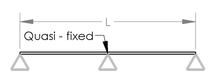
The most common beam support is supported at both sides also known as simply supported. This beam is already fairly stiff and easy to construct. However, if we make one beam span three supports, we have actually changed the center portion to a nearly fixed support. I say nearly fixed because the support can still rotate at the center position. However, this support is still attached to the other ends so it must take some moment at the center support. If this maximum load on the beam is symmetric about the center support, we can assume the joint is fixed in the center. This will make our same beam 2.4 times stiffer than it was before. This is a small change that boasts great results.
Add a Cantilevered Section on the End(s)
This is a way to keep the same total beam length while decreasing the distance between the supports. From the hierarchy listed above, a simply supported beam is 9.6 times more stiff than a cantilevered beam this means that I could actually cantilever the beam off one end by 10.4% (1 / 9.6)

For example, if I had a 100 inch simply supported beam, I could move the support on one end in roughly 10% of the total length. This not only reduces the deflection by 31% (results depend on materials used and cross section), but also when used in decking gives the feeling of the deck stretching past where it should. A great feeling for a deck owner.
You can do this on both ends of your beam if necessary.
Increase the Area Moment of Inertia
Looking at the generic beam formula below, we can see that if the moment stays the same, only the area moment of inertia. I, and the modulus of elasticity, E, can be modified to reduce deflection, v. In this section, we will discuss the area moment of inertia.
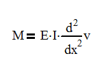
The area moment of inertia is entirely based on the shape of the cross section. As the cross section increases, so does the moment of inertia. In fact for a rectangle, if you double the height, you will quadruple the moment of inertia. However, if you double the width, you only double the moment of inertia.
Here’s what to do with the following structural shapes
Round Tubing or Pipe
With round tubing or pipe, the easy solution is to thicken the wall. For example, 1/4″ thick tube becomes 3/8″ thick or schedule 40 changes to schedule 80 pipe. You will only see moderate increases in stiffness as the wall thickens. This may be enough, but your section is becoming heavier. At some point the additional weight may actually increase deflection.
The best solution is to increase the outside diameter of the tube or pipe and keep the original wall thickness. If this is not possible, consider switching to a square tube.
Square Tubing
Square tubing is very similar to round tubing, but it does have the advantage that all the material is on the outer edge and is great for bending in both the horizontal and vertical directions (assuming a horizontal beam). With this in mind, be sure that the flat surface on the tube is oriented with the largest moment on the tube. The tube isn’t as strong when it is loaded as a diamond.

Angles
Angles just don’t make good beams. If you are having troubles with your angle deflecting too much, consider changing it to a different shape. Any shape is better. Just do it. You’ll thank me.
Wide Flange Beams
Wide flange beams offer a wide variety of solutions for your design. There are so many sections to choose from and often you don’t need to increase your height to make a dramatic change in strength.
| Beam | Moment of Inertia (in^4) | Increase | Weight Compared to W16 x 31 |
| W16 x 31 | 301 | – | – |
| W16 x 45 | 586 | 1.94 | 1.45 |
| W16 x 67 | 954 | 3.16 | 2.16 |
From the table above, you can see that going from a W16 x 31 to a W16 x 45 doubles the stiffness while only increasing the weight 45%. Going to a W16 x 67 doubles the weight and triples the stiffness.
If your wide flange beam sees loads on the weak axis, consider boxing the sides in. Generally speaking, the plates don’t need to be very think to make a big impact.
Increase the Modulus of Elasticity
Increasing the modulus of elasticity is difficult to do in most cases. Pretty much the only way to increase this is to change the material. If you are already using steel, you’re on the top of the food chain; there is no more room to improve.
There is a lot more room to in the realm of plastics and non-steel metals. Often changing from a standard plastic to fiber reinforced plastics, fiber glass or carbon fiber is a good move.
Below is a list of common items and their modulus of elasticity sorted from highest to lowest. If you need to minimize deflection, consider a material higher up on this list.
| Material | Modulus of Elasticity (ksi) | Material | Modulus of Elasticity (ksi) |
| Tungsten | 59465 | Zinc | 12000 |
| Monel | 48000 | Gold | 10733 |
| Inconel | 31000 | Aluminum | 10008 |
| Steel | 29000 | Glass | 7252 – 13053 |
| Nickel Steel | 29000 | Tin | 6817 |
| Nickel | 25000 | Chromium | 5221 |
| Carbon Fiber Reinforced Plastic | 21756 | Beryllium Copper | 2611 |
| Gray Cast Iron | 18855 | Wood (Douglas Fir) | 1885 |
| Silicone | 18855 – 26832 | Wood (Oak) | 1595 |
| Nickel Silver | 18500 | Medium Density Fiberboard – MDF | 580 |
| Aluminum Bronze | 17405 | Acetal | 406 |
| Copper | 16969 | Polycarbonate | 377 |
| Phosphor Bronze | 16824 | PVC | 348 – 595 |
| Titanium Alloy | 16000 | Nylon 6-6 | 290 – 580 |
| Brass | 14794 – 18130 | HDPE | 116 |
| Bronze | 14504 | LDPE | 16 – 65 |
Add Other Beams to Share the Load
Adding more beams to carry the load can be an effective way of minimizing deflection. If we have one beam and add a second, our deflection will be cut in half. Excellent!
However, if we have 2 beams and go to three, we may end up with the same deflection if you don’t plan your beam locations right. Assuming a distributed load across the width of the beams, the center beam may take 1/2 of the load and the outer beams only take 1/4 of the load each. The figure below illustrates this point and the equations give the load on each beam.

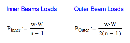
Where w is the distributed load, usually in force per area (N/m^2 or psf), W is the width of the structure and n is the number of beams.
The center beam is responsible for 18″ of the load width and the ends are only taking 9″ of the load. This is why adding another beam in this manner is counterproductive.
Now, to get each beam carrying an equal part of the load, we need to move the outer beams in so that the distance from the center of the outer beams to the end is half the distance between the beams. The figure below shows the proper relation.

This works because each section of beam is responsible for 6 inches of the load to each side.
The next time you drive under a concrete bridge, look and see how the girders are spaced.
Learn More
Best Guide to Determining Deflection in Variable Cross Section Beams
The Best Guide to Solving Statically Indeterminate Beams
How to Calculate Beam Data When Your Case Isn’t in a Table
In Summary
There are many ways to minimize the deflection on a beam. Looking at the loads, supports, section properties and the material will allow you to see what options are available to stiffen your beam.
Hi Corey,
With reference to “Non-equally loaded beam with center support”, where did you obtain the formula for inner and outer beam loads? With reference to https://structx.com/Beam_Formulas_041.html the outer should be 0.375w and inner should be 1.250w.
Very much appreciate your input.
Thanks!
Asif,
Thanks for the comment. I have limited availability but I will respond in the next few days with a full answer.
Asif,
According to the calculations the equation for a uniformly loaded, simply supported beam is M=w*L^2/8.
The equations you gave for M1 and M2 are w*l^2/8 and 9*w*l/128. We would then need to substitute l = L/2. We end up with the beam is 3.5x stronger at M2 with the center support and 2x as strong at M1.
Hi Corey,
Thanks for getting back. I’m sorry but I did not understand your reply.
With reference to “Non-equally loaded beam with center support” I can’t source the reference or how you arrived with the formula:
Pinner = (w.W)/(n-1) = w/2
Pouter = (w.W)/2(n-1) = w/4
I am keen to know where the above formula comes from
According to the other website, the table shows
Pinner = (10.w.L)/8 = (5/4).w
Pouer = (3.w.L)/8 = (3/8).w
Thanks once again
Asif,
I used the formula from the link you sent for a uniformly loaded beam with 3 supports. The other reference was Omer Blodgett’s Design of Weldments case 3B.
Corey,
Thanks for your prompt reply.
Pinner = (w.W)/(n-1) = w/2
Pouter = (w.W)/2(n-1) = w/4
The above, I can’t source anywhere, specially with (n-1) and 2(n-1). Blodgett’s’ has no mention of it
Will try to dig in and keep you informed.
Thanks