Roller Coasters can be dangerous. When accidents happen, they are to be taken very seriously. Root causes need to be found and addressed.
There was an incident on the Black Widow where the bogie came off the track and got wedged on the main drop. Watch the video to see why this happened and what we did to fix it.
In college we learned all about torsion and the polar moment of inertia. However, school can be over simplified at times. A colleague and I learned this the hard way.
We were designing a 20 foot (6m) lattice structure with 4 angle irons running lengthwise. About every 24″ we ran a cross member making a rectangle to hold the section together. We also added in diagonal angles to carry the moment load on the lattice.
I suggested that we do a torsional calculation like we learned in school to figure out if it was strong enough. We used the section properties in Solidworks and it boasted a high Polar Moment of Inertia and low torsional stress. We continued with our design.
Typical Lattice Boom Structure. Image is Public Domain
A few weeks later, we starting running Finite Element Analysis on the design and the structure lit up like a Christmas tree! At first we thought it was an error in the loading, but we quickly realized the problem. The torsional deflection was excessively high.
We went back and calculated our torsional deflection again and found no issues. Now, it was time to summon to “old guy” to come help us out. It didn’t take but 2 minutes for Marvin to set us straight; the traditional formulas for torsion just don’t work on open sections.
The Polar Moment of Inertia is a member’s ability to resist twisting from torsional loads. Resistance to torsion is based entirely on the shape of the section and not the material properties. The Polar Moment of Inertia can be used to calculate shear stress and torsional deflection.
Traditional Polar Moment of Inertia Formulas
The traditional formulas for the polar moment of inertia work only for closed or continuous sections. These are sections like round bars and tubes. If a section has a few holes or a short slot in it, it is still considered closed. However, if the slot is substantial in length, you now need to consider this as an open section. Knowing if the slot is substantial depends on the beam shape and length, slot length and torque applied.
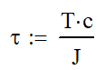
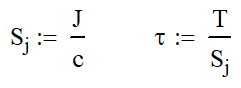
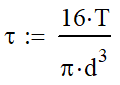
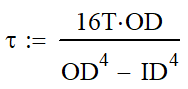
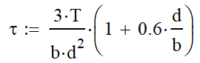
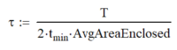
There are two main equations where the polar moment of inertia is used. The following equation will calculate the shear stress in a section. τ is the shear stress, T is the torque applied, c is the distance from the centroid to the outer fiber and J is the polar moment of inertia.
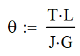
The other equation is for finding the torsional deflection. θ is the angle of deflection in radians, L is the length of the member and G is the shear modulus of elasticity of the material. G can be looked up in reference tables or calculated from Young’s modulus and Poisson’s Ratio
Calculating Polar Moment of Inertia
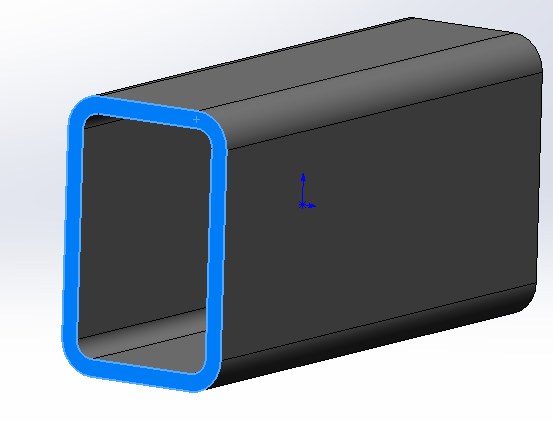
If you have 3D CAD modeling software, you can easily “calculate”, er…find the polar moment of inertia. If you are using Solidworks, first select the end of the section. Then go to Tools->Evaluate->Section Properties.
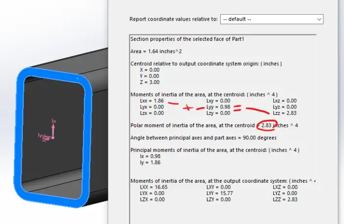
This will bring up a lot of information. Don’t get overwhelmed because we don’t need most of it. The circled number is the polar moment of inertia at the centroid. In the section above that, you will get 9 numbers and 6 of them will be zero. The ones that aren’t are the area and polar moment of inertia.
One thing to note is that the two are moment of inertia will add together to give you the polar moment of inertia. This means that it will always be the largest number there, which prevents confusion when your coordinates may be in a different orientation.
Every major 3D CAD software has a method to look up the section properties. Take a few minutes to do a web search. If you don’t have 3D CAD, why not? I guess we will have to do this the old fashioned way. No not calculus…look it up in tables.
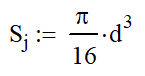
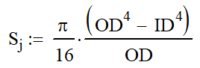
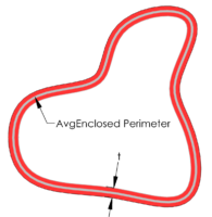
The table below has the polar moment of inertia for common shapes. Here are the Polar Moment of Inertia on common shapes. I have add a column for the “Torsional” Section Modulus, Sj, which is a term that I have come up with. It is similar to the section modulus for bending, but it is used with torsion. In many cases, it will speed the calculation process along, but in others it will only make it more cumbersome.
Torsional Section Modulus Equations
I just want to reinforce that I have not seen this method formally taught, and I made up Sj. If you have a better denotation, please share it with me. My contact information is in the footer.
Torsional sections with thin walls are susceptible to buckling and denting. Soda cans are strong in torsion, but dents cause stress concentrations and buckling with shrink the enclosed. Both reduce the torsional capacity of the section.
Shape
Image
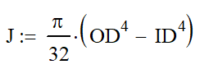
Polar Moment of Inertia
Torsional Section
Modulus
Stress Formula
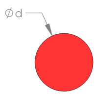
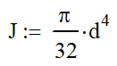
Round Bar
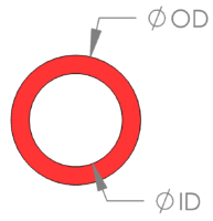
Round Tube
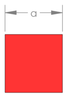
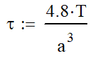
Square
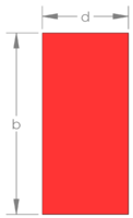
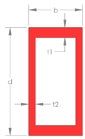
Rectangle
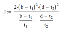
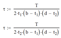
Rectangular Tube
Hollow Blob
When Not To Use the Polar Moment of Inertia Formulas
The situation above taught me a lot about torsion and how unique it can be. In the first weeks of my strength of materials class, we learned that the maximum shear stress occurs about 45° from the maximum axial stress. This gives great insight how to visually see torsional stresses in beams.
If I think about an axial stress wrapping around the outside of my section at a 45° like the candy cane below, I can see where there is a clear path and where there isn’t. These are what we call closed and open sections, respectively,
Shear stress flows at a 45° angle around the section’s surface like the stripe around a candy cane. Visualizing this will help design strong torsional sections.
The lattice boom is a clear example of an open section. Using the candy cane method, the flow of stress quickly falls apart. There is no clear and direct path for the stress to flow. Open sections need special care and there aren’t many clear cut formulas .
Traditional Stress-strain calculations for torsion only work for closed or continuous sections. Open sections, like a lattice structure, need to be analyzed by torsional resistance. Omer Blodgett’s Design of Weldments gives a great method to calculate torsional resistance.
Wherever possible, try to use a closed section like a bar, or tube. Even if you have an open section in torsion, there are ways to improve the torsional rigidity in a member. The following article details ways to minimize torsion in common applications.
In order to design a better section for torsional deflection consider using closed sections like bars or tubes; avoid plates and structural shapes. You can also box in open sections, thicken walls and apply bracing.
At a former job, we frequently encountered this following issues when a torsional load was applied to a round tube with a hole in it. As we made the hole larger, this became more of an issue. We solved it by making the hole a diamond with rounded corners. The forced the candy cane stress to pass easier where it could and reduced the maximum stress.
Rodless cylinders is a cylinder without a rod. It seems like a stupid idea because if there isn’t a rod, how does it do work?
I accidentally discovered the concept of a rodless cylinder a few years ago on the job, I didn’t know it was an actual thing then. We had a clamping system powered by two pneumatic cylinders. In the process of installing the machine, we were doing some grinding and the dust stuck to the aluminum cylinder without us knowing.
Direct Mounted Rodless Cylinder Assembly
Once the system was ready, we stroked the cylinders and all of the dust collected into one spot. The spot where the piston was. We now were stroking the cylinder to watch the dust move with the cylinder. It was like we were kids in a candy shop again.
Apparently, the piston was magnetic and we couldn’t leave it alone; Challenge Accepted! We were finding steel plates and other magnets to see how much this could lift. It ended up being several pounds. We just made a rodless cylinder. (I later found out that most pneumatic cylinders have magnetic pistons so that the position of the rod can be monitored with a sensor.)
This concept also popped up as I was searching for ideas on how to make a launch on my roller coaster. Pneumatics can be a great method of propulsion and I stumbled upon the video below. This man built the largest rodless cylinder I have ever seen. In fact, it is a continuous loop!
A rodless cylinder is a cylinder with no rod. Output motion is achieved by attaching to piston either through direct connection or using magnets. The piston is moved through the cylinder by applying compressed air (or vacuum) at the ports. With no rod to extend, the cylinder is compact and doesn’t get larger.
So the first question you probably have is how do you attach to the piston without leaving a gaping hole in the side? Good question!
Magnetic Attach Rodless Cylinders
Let’s start with the easy version, magnetic coupling. As we found in the shop that day, you can design a cylinder with a magnetic piston and then attach things on the outside to ride along. With this design, it is easy to seal and there is no air leakage.
There are some limitations that we need to address. First, there is a limit to the forces and moments that can be applied to the cylinder. The internal magnets can only hold a finite load. If the load is exceeded, the outer magnets can slip off from a high shear load (sliding) or a high moment load (prying). To mitigate this, longer pistons can be used to give a wider stance for the prying loads.
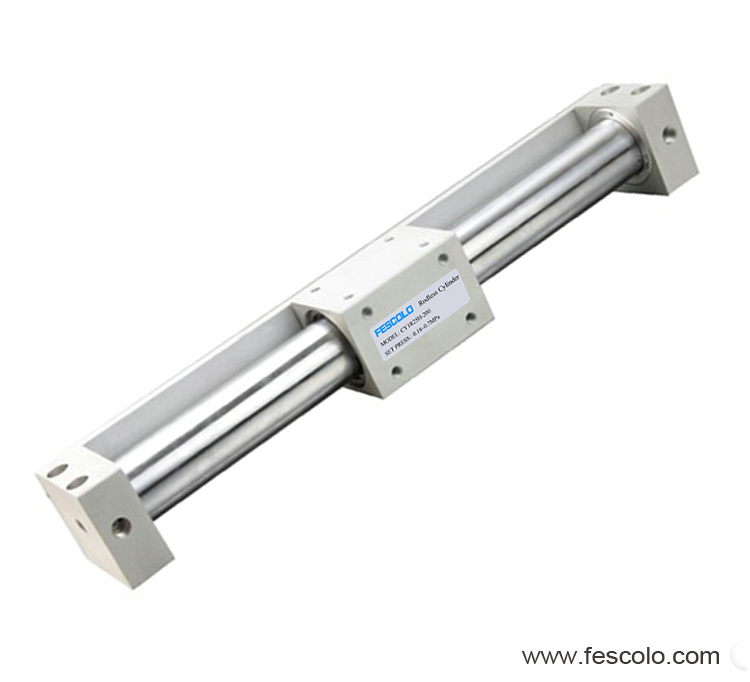
Typical Magnetic Coupled Rodless Cylinder Image courtesy of Fescolo
Second, it is a bad idea to have hard steel plates or magnets running along the side of the cylinder tube. These tubes are usually aluminum and could wear out. If higher moment load is need, a guide rail system can be added for support.
On thing about magnets is that you loose force very quickly as the gap gets larger and larger. These instruments have close tolerances as a result and dust and dirt can cause sticking and binding. Magnets also have a tendency to find any ferrous material in the area. Generally speaking, you will want to use this in a relatively clean environment.
Despite these disadvantages magnetic rodless cylinders are strong and robust.
Direct Mount Rodless Cylinders
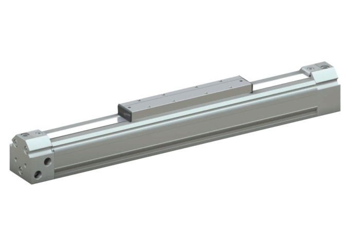
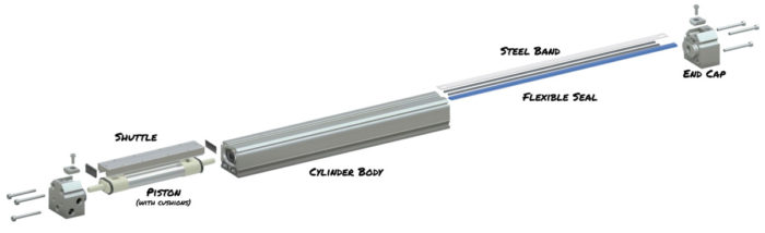
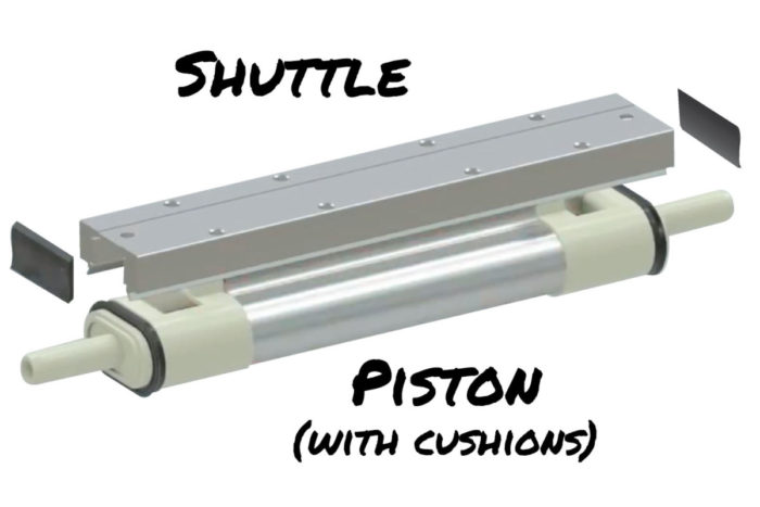
Directly mounting your apparatus to the piston is a trickier task. As shown below, there are a few more components involved. Using a flexible inner seal, air pressure can be maintained without leaking. An outer steel band is used to make sure that no one punctures a hole in the inner seal. A shuttle is also mounted to the piston for the purposes of easy mounting to your application.
Typical Direct Mount Rodless Cylinder Artwork by Stephen Schandel
8 Tips for Selecting a Rodless Cylinder
If you go to a resource like McMaster Carr (best website in the world) and buy a rodless cylinder, you will probably pick the wrong one at first. Don’t buy it until you read the rest of this article. You will probably find that you need a different one.
In order to select a rodless cylinder you need to: evaluate the air pressure, plan for size and stroke, calculate loads and moment in static and dynamic conditions, account for impact loading and friction and consider the operating environment
1. Get an Accurate Pressure Reading at the Location
I have been burned by this twice. The first time was because I didn’t notice that due to line distance, the pressure had dropped 8 psi between the compressor and the where I needed it. Now, my cylinder wasn’t able to move the load fast enough because there wasn’t as much force to overcome inertia.
After that, I made it a habit to check the pressure of the connection when I designed a pneumatic system. This leads me to the second time I was burned. This time, I went in early in the day when few people were working. The machine I was working on was at the far end of the shop and was going to require a fair amount of flow to complete the task. Knowing the pressure was good, we proceeded with the design, but when it came time to fire up the machine, it worked great from 6 am to 7am.
After 7 am, everyone else starting using air tools and there wasn’t enough flow on the line to power all of the demand. However, there was still plenty of capacity at the compressor. The problem was the size of the line coming off the compressor to power all of the tools. We mitigated this problem by running a parallel line that only serviced my machine.
2. Plan for the Required Stroke
All cylinders have “dead length” in them. This is the total length when retracted minus the stroke. This length is mostly taken up by the end caps, cushion and piston. A rodless cylinder will have a longer dead length than a traditional cylinder. Often, this can cause issues when trying to fit it in the design. The manufacturer should provide this information for you.
3. Calculate the Loads
Calculating the load on a regular cylinder can be difficult, but it is worse on a rodless cylinder. The reason for this is that a normal cylinder will have the majority of its load along the center-line. This means that there is little side loading on the rod, piston and seals.
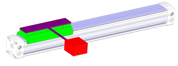
Because the load isn’t in line with the bore, rodless cylinders will always have an moment on them. Both the green shuttle and red mass are off center from the cylinder.
However, with a rodless cylinder, your load is going to be off center, which contributes a moment load to the cylinder. If I have a mass of 5 lb. that I am trying to raise at a distance of 10 inches from the cylinder center line, not only am I going to have to lift the 5 lb, but I am also going to need to support a moment of 50 in-lb. This can cause havoc on any cylinder.
4. Dynamic Loads
But it gets worse! We also need to calculate in the dynamic loads as well. Since we are dealing with compressible fluids, we can have rather large accelerations. In some cases, like reaching the end of the stroke, the load could be double. This would raise our 50 in-lb to 100 in-lb. If this isn’t planned for, your cylinder isn’t going to last very long.
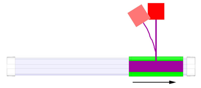
As the shuttle moves from left to right, the red mass will lag behind. When the shuttle stops, the mass will swing to the right. Both cases cause extra moment to be transferred to the cylinder.
5. Size the Bore Properly
Once the loads have been calculated, we can calculate our bore size using the tried and true formula of force = pressure * area. Know our force and pressure as we can calculate the area and bore diameter. I usually add in an efficiency factor of 90% to 94% for cylinders. I would use the lower value of 90% for a rodless cylinder to accommodate not only friction, but also an increased breakaway force from side loading the cylinder.
6. Add Cushions or Shock Absorbers
Anyone who deals with pneumatics knows that it is difficult, if not impossible, to accurately control the position of a cylinder. It is for this reason that most cylinders are designed to either push up against something (clamping) or go full stroke.
If it is designed for full stroke, you will bang against the end of the cylinder. This is bad enough for a normal cylinder, but can be detrimental to a rodless cylinder. Most manufacturers would have you double the average velocity for the impact velocity. If your velocity was 12 inches per second, you would want to run your cylinder calculations for 24 in/s.
A good way to mitigate this problem is to add internal cushions to the design. Most manufacturers will have this option available (for additional cost of course). A cushion does exactly what it sounds like; it cushions the cylinder motion at the end of the stroke. It accomplishes this by cutting off flow as the cylinder reaches the end of the flow.
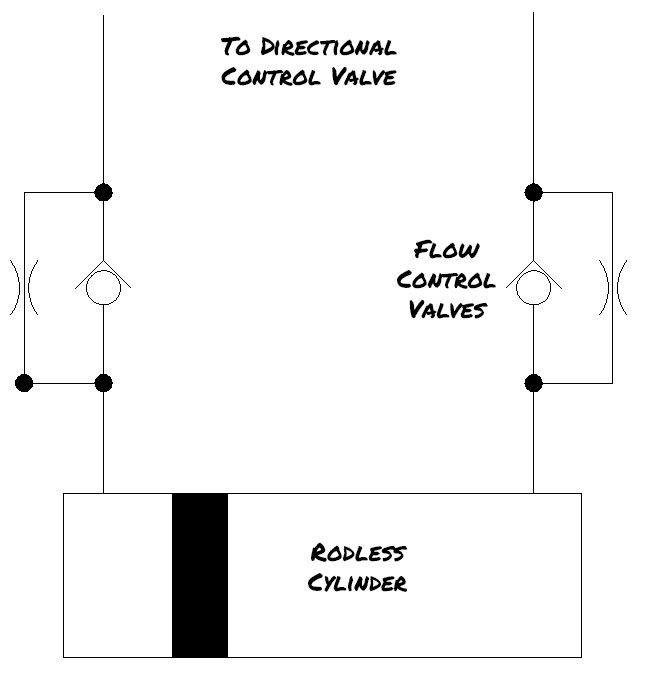
The flow control valves limit the air going out of a cylinder. If air is coming in at the top left moving the cylinder piston right, it will flow freely through the check valve creating high pressure. The check valve on the right flow control valve will force air through the needle valve resulting in slow and controlled motion.
Pneumatic cylinders are best controlled by metering (restricting) the flow out of the cylinder and not into the cylinder. This is because a compressible fluid will tend to jump as it moves. If we meter out the flow, we keep the forces on both sides of the piston high. The high internal pressures will be much higher than the friction force. This results in much smoother travel when we meter fluid out.
Cushions on pneumatic cylinders will restrict the outflow of air. This is done by the tube looking ends on the piston shown above. The tubes are slightly tapered and fit into a tapered hole in the cylinder end cap. The tapers will not touch, but as they move closer, it will restrict the flow of air causing the piston to slow down before the end of stroke it reached.
Shock Absorbers are another way of cushioning or perhaps adding extra cushion. Shock absorbers are readily available in a variety of shapes and sizes. Check out McMaster Carr to get started.
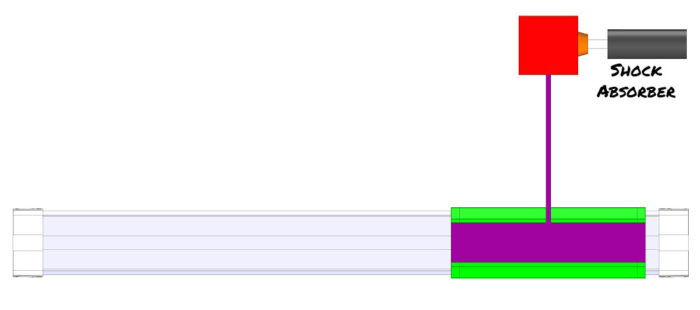
Adding a shock absorber to slow the mass and an internal cushion will prevent transferring high dynamic loads to the cylinder.
Even if your cylinder has a cushion, you may want to consider adding an external shock absorber to cushion the load. This will slow the load down preventing the transfer of moment to the cylinder. It also may allow you to reduce the size of cylinder.
7. Consider Orientation
Because of the cantilevered loads on a rodless cylinder, the installation orientation will effect performance. In a horizontal application, performance will be similar in both directions.
If we re-orient this to vertical direction, the cylinder will raise slower and fall very fast. This will include a much larger moment at the cylinder. This may not be desirable. When lowering a load, you may now need to lower the pressure, but also add a flow control valve to slow down motion.
8. Understand Operating Environment
With any mechanical component, we need to carefully consider the operating environment. As mentioned before, rodless cylinders generally need to be kept in a clean environment where dust and dirt aren’t prevalent. As a result, you will typically see these inside in industrial areas. Perhaps they are in a sealed unit with filtered air to keep contaminates out.
Other consideration may need to be made for high temperatures and corrosive chemicals (they deteriorate seals).
Having a good preventative maintenance routine is essential for a long life. It is recommended that these get weekly or even daily cleaning. Keeping the tracks clean will prevent premature wear.
Summary
Rodless cylinders are a wonderful invention. I believe that they are just in their infancy and will continue to be used in industrial applications more and more. With their compact size and high force, they are an excellent choice for motion.
Be sure to consider using a rodless cylinder the next time you design a machine.
Why Frameless Motors are Important? Practical Applications
As technology improves, mechanical designs have become sleaker and more compact. One exception has been electric motors. For decades, the shape and form factor of a motor has remained constant. Its consist of a large cylindrical body with a shaft protruding out one side.
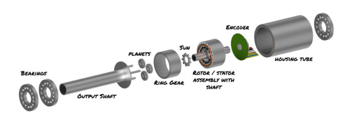
If you are trying to accurately control motion in a joint, this can lead to a bulky situation. In many applications you are going to need: a motor; a gearbox to reduce the speed or change direction of motion; an encoder to map the position; bearings to support radial and thrust loads; and hoses or wires to be routed external to the whole apparatus. What A Mess!
Well, that has all changed; for the better! The Solution: Frameless Motors
A Frameless Motor separates the components of a traditional motor and removes the housing (frame) and bearings. The stator and bearings are built into the structure removing the need for duplicate structure and bearings. A low profile encoder can also be added. The rotor is inserted and can be designed with a hollow shaft allowing hoses and wires to pass.
How Does A Motor Work?
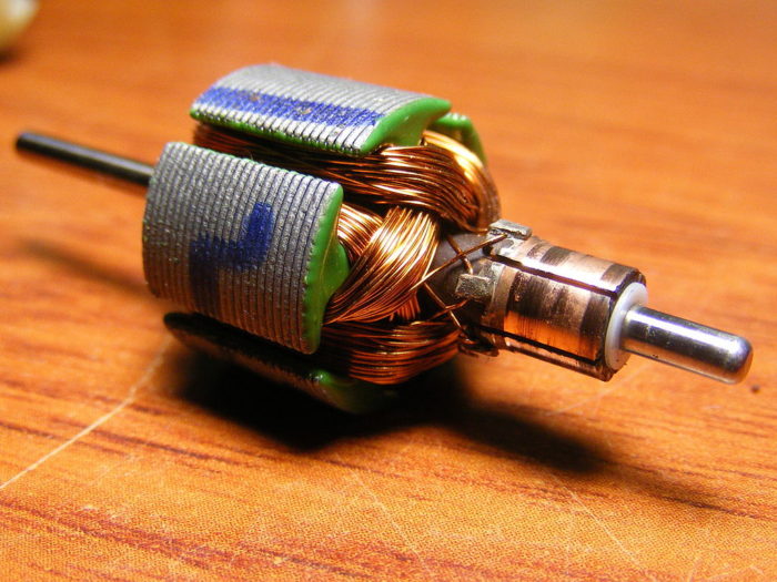
In a DC (direct current motor), there are electromagnets, minimum of 6, attached to a rotor (spinning part). The rotor is placed in a stator which has permanent magnets mounted on opposite sides.
On the rotor there are contact pads (on right). These contact pads are connected to two electromagnets having opposite polarity. Brushes are used to transfer the electricity to the rotor on the contact pad, which energizes the electromagnets. As a result the magnets will want to attract and turn the shaft.
As the shaft spins, one set of brush contacts will drop off as another is being turned on. This ensures that a DC motor will always be able to give full torque.
DC motors aren’t they only type of motors out there, but they are the easiest to understand how they work. AC motors are speed controlled by the drive frequency which is 60 Hz in the USA and 50 Hz most other places. There are also stepper motors and synchronous motors.
All motors have the same two components, the stator and the rotor. The stator is the stationary outside component and the rotor will turn when electricity is applied.
Traditional Motor vs Frameless Motor Application
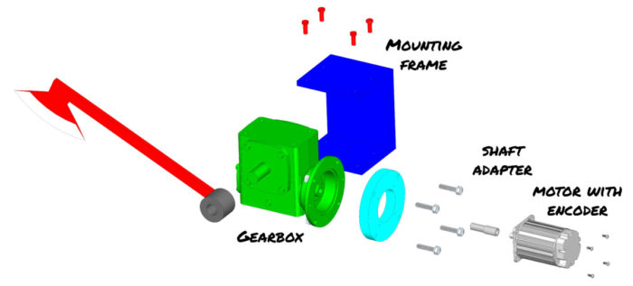
In a traditional style motor application you will have the components shown below. There is a lot of redundant structure and multiple bearings. Many times the motor shaft and gearbox shaft are not the same diameter and need a shaft adapter. In this case, we need the light blue spacer plate to compensate for the shaft adapter and to allow mounting to the motor. There is so much redundancy and we have little control over the components available.
In this traditional style motor powered axe application, there is a lot of redundant structure and components.
The gearbox also mounts oddly because it has a hole pattern on top and bottom. This means that it must be sandwiched in between two plates. As someone who designs welded structures, this is difficult to do as the welding process will distort the gap. Once welded, there is little opportunity for adjustment if the gearbox is misaligned.
In a frameless motor application, this is all changed. The entire assembly mounts the round tube on the right. If this is part of a robotic arm, you can weld the tube to the end of the arm and then bore out the tube. This will account for any misalignment.
In the diagram below, you can also see that all of the components will fit in a much smaller envelope (and it looks cooler).
Custom Artwork By Stephen Schandel
We have reduced the number of bearings from 6 (4 in gearbox, 2 in motor) to 3. This will result in less friction and greater efficiency.
Benefits of a Frameless Motor
Just because something is different, doesn’t mean that is it always better. With frameless motors, there is a significant benefit in many applications.
The main benefits of frameless motors are increased efficiency and productivity, reduction of components like bearings, reduction of structure, smaller footprint, and improved hose and wire routing. All of these combined lead to lighter weight and decreased maintenance.
A better way of saying this is a frameless motor lets you have control! As the designer, you have complete control over every aspect of the design including the form, fit and function. No more adapting a design to the motor’s frame size.
Let’s explore this more closely
Increased Efficiency and Productivity
Gearbox
Going to a frameless motor usually means using a larger diameter motor. This can be very beneficial because a large diameter motor can produce more torque. Traditionally, if you needed more torque, you had to use a gearbox to increase torque and reduce speed.
Gearboxes have inefficiencies from the gears meshing which is wasted energy. Unless you get a precision gearbox, there is an issue of backlash or slop. Backlash is a measure of how much the input shaft can be reversed without any change on the output shaft. If you are looking for precision positioning, this can be difficult if not impossible.
With the larger motor diameter, there will be greater torque generated from the motor and you can completely eliminate the gearbox. No more slop and it will run quieter. Think about it, noise is just wasted sound energy.
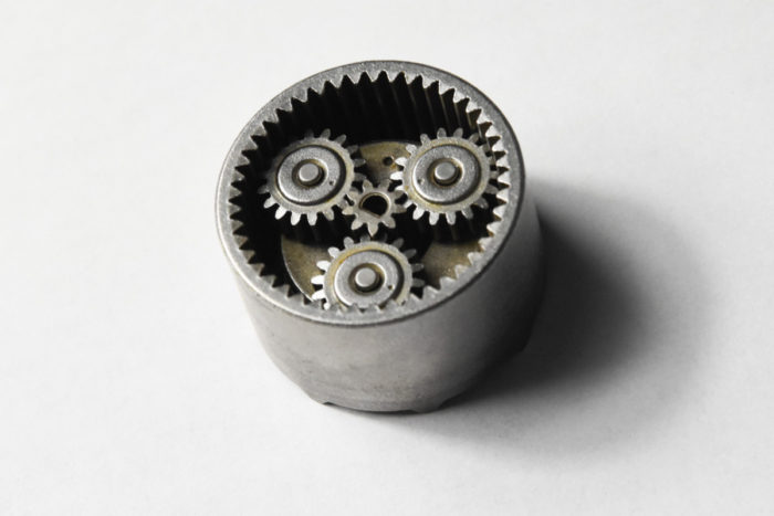
This simple 2 stage planetary gearbox provides a 36:1 ratio and easily presses into the same tube that houses the stator.
If you still need a gearbox to get the torque you need, consider incorporating a planetary gearbox into your design. The sun, in this 2 stage gearbox in this is a 36:1 system shown above, can easily fit onto a motor shaft and then be pressed into the housing. This can be done with the addition of only one bearing on the output shaft.
Bearings
Bearings are also a source of inefficiency. Each bearing creates resistance to motion and a traditional setup has lots of them. Think about it: there are 2 in the motor, 2 to 4 in the gearbox, and 2 more on the output shaft. Two more if you need an encoder. That’s a lot of bearings!
In a frameless design, we can remove the gearbox due to the increased diameter. We can also incorporate the motor bearings into the output shaft bearings reducing it by two more. The brains of an encoder are relatively small and there is no need for it to have any bearings.
We have now reduced our assembly from 10 bearings to 2. Yea!
Reduction of Components
All these components that we have eliminated contribute directly to increased productivity. First of all, we have eliminated the hassle of purchasing, managing, and storing multiple parts. This is a hidden cost in any design.
If we don’t have to buy these parts, we also don’t have to assemble them. Now we can produce more product in the same time.
Finally, when there are less components, there is less that can go wrong. This leads to the product having longer up times and reduced time troubleshooting when something does.
Reducing components directly leads to increased productivity and a more durable machine.
Faster Motion
Another way that production is improved is with movement. When using a gearbox, you may be limited in your input speed. If you have a very high ratio gearbox and you might have a slow output speed which means slow travel from one position to another.
If a gearbox can be removed, this will lead to faster settle times. This is the time it takes for the motor to hone in on the final position. I once had an apparatus where a motor drove a chain that controlled linear position. When it got close it would slow down, but as it did, it became jumpy.
By jumpy, I mean that it would move 1/8″ (3mm) and then stop for a second before jumping again. It was very difficult to position it closer than 3/16″ (5mm). The settle time on this was very lengthy (over 15 seconds) because the chain would oscillate on each side of the target multiple times. We ended up switching to a precision gearbox and increasing tension on the chain. This removed most of the backlash and we were able to get the settle time down to 2 seconds.
Reduction of Structure
If we buy the gearbox, motor and encoder separately, we are going to have housings for each of them. This is wasted material and money.
In a robotics application, this can be a lot more mass that needs to be repositioned. Since Force is mass x acceleration, we are going to need more force to move this. With more force comes larger structures, more weight and more energy to move it.
By combining the motor, encoder and gearbox into one structure, we minimize weight and footprint. This leads to less power needed and greater system efficiency.
Improved Hose / Wire Routing
I can’t say how difficult it is to route hoses and wires external to moving joints. As the joint moves, the wires will tighten and loosen. Too tight and they might snap or kink. Too loose they might catch on something. It is a delicate balance.
I did work on one aerial lift where the hoses were routed through a hollow shaft. This was a godsend because the unit was designed to work around trees and the hoses were well protected from getting snagged. As the joint changed position, the hoses rotated on the center-line, but never changed length.
A slip ring allows for continuous rotation of the wires without twisting. One side is mounted to the stationary end and the other rotates with the output shaft. The wires can run through the hollow shaft that a frameless motor allows. Servotecnica, CC BY-SA 4.0 https://creativecommons.org/licenses/by-sa/4.0, via Wikimedia Commons
The same can be true in a frameless motor. You can choose a shaft that is hollow and run wires and hoses through it. This protects the wires and prevents them from changing length. If your application is for non-continuous rotation, you can simply run the wire and hoses in the hollow shaft. However, if you need continuous rotation, you still have the opportunity to add a slip ring or rotary joint to the design. The hollow shaft is magic!
Decreased Maintenance
Improved OEE by increased machine life and reduced maintenance. Similar to the above point, each additional component in a system adds complexity and the need for maintenance. Since frameless motors use comparatively fewer components, they also require much less maintenance than traditional motors.
Summary
From increased productivity, reduced structure, size and components; frameless motors are here to stay! I can’t say enough how much having the ability to run wires in a hollow shaft is a major benefit.
The one main drawback is cost. Some of these components like the shaft and housing are going to be custom. This leads to parts needing to be machined.
Every situation is different and needs to be evaluated. Even in small quantities or one-offs, using a frameless motor with a lot of machining will still make sense when factors like size are important.
Well, the capstan just isn’t holding up well enough and the rope is wearing out. Its time to improve the design. Let’s look at one of the greatest launch systems in existence for guidance: Top Thrill Dragster.
Watch and see what happens when we modify the system.
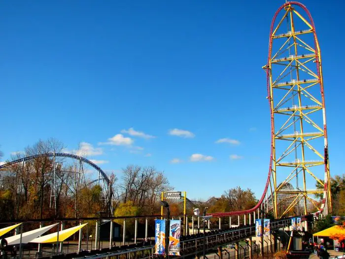
If you’ve ever ridden it, you know the mere 17 second ride on Top Thrill Dragster is nothing less than perfection. You are accelerated to 120 mph (193 kph) in under 4 seconds and then rushed over a 420 foot (128 m) top hat before spiraling vertically back to the ground. Breathtaking.
Top Thrill Dragster – Image Courtesy of Jeremy Thompson
Intamin Amusement Rides didn’t just build one, it coexists with its big brother Kingda Ka (Six Flag Great Adventure) and little siblings Storm Runner (Hershey Park) and Accelerator (Knott’s Berry Farm). I’ve ridden all of them except Accelerator. (Ironic, because I used to work there.)
Top Thrill Dragster has been dubbed the king of them all because it’s launch is a little more intense. (I believe that Kingda Ka would be better if they removed the over the shoulder restraints)
Top Thrill Dragster is launched by temporarily connecting the train to a “catch car” on the launch track. The catch car is pulled by cables along the launch and cables are wound and unwound on a large reel. The reel is powered by 32 hydraulic motors which are powered by a 2000 hp hydraulic accumulator system.
Launch Sequence
The launch sequence of Top Thrill Dragster is very complicated, but I will simplify it as much as possible. Please note that within each sequence hundreds of individual mechanisms need to be assessed before launch can occur (over 800 total). This means things like the loading gates are closed, all the restraints are locked, brakes are operational and the track ahead is clear. A good comparison is preparation for launching the space shuttle; every system has to give a “go / no go” for launch.
Once the passengers are loaded into the train, two trains advance out of the station. The rear train stops on a holding block section while the other heads to the launch section. At the launch section, the cable drive system will place a catch car under the train. At this point, an electromagnet will energize causing the launch dog on car 3 to lower. You will hear a clank when this happens.
The train brakes will release and roll back about 6 in (150 mm) until the launch dog mates with the catch car. The brake fins are lowered and a final system check is done before launch occurs, accelerating the train to 120 mph in under 4 seconds.
Once the train has passed, the brake fins on the launch will raise up in case the train doesn’t have enough momentum to clear the top. This is call a “rollback” and the train will slow on the launch track. The system will reset and launch will occur again. We will discuss this in more detail later.
Kinematics of Acceleration
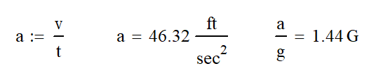
The forces involved to launch the train are nothing short of impressive. If we assume that the launch acceleration is linear or constant, we can calculate the G force is 1.44 times the acceleration due to gravity. Impressive for a launch. Lightning Rod at Dollywood is probably the closest launch to this, but it is aided tremendously by the grade of the launch.
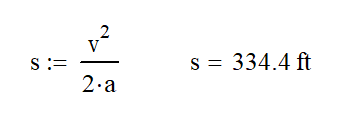
We can also use the following kinematic equation to determine the minimum launch length of 335 ft. We will actually need quite a bit of extra length in the launch for two reasons.
First, there will need to be some wiggle room in the system to tune the launch system. If the train isn’t moving fast enough we need extra launch to get over the top hat. Allowing for 30 ft to 50 ft (9 to 15 m) of extra launch length may do the trick. This section of track could also be used to monitor the train speed before it detaches from the catch car.
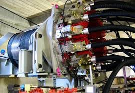
To put the system size into perspective, a team of maintenance workers are replacing one of the 32 hydraulic motors
Second, we also need a section of launch track for the catch car and cable reel to slow down. The cable launch reel is nearly 7 foot (2.13m) in diameter and carries with it large rotational inertia which can’t be stopped instantaneously. The catch car is also heavy and needs some time and distance to slow down. If we try to slow it down too quickly, we would get the same effect as if you threw a flag pole in your bicycle spokes; you’ll end up snapping a cable or stripping teeth off the gears.
Launch Force
The force involved for launch can be calculated since we know the acceleration using Newton’s Second Law: Force = mass x acceleration. Cedar Point has indicated that a train has a mass of 15 tons (13,600 kg) empty and we can calculate that the average loaded train weight is 16.6 tons (15,000 kg). At first, I couldn’t believe that the trains weighed that much, but then I realized two things.
First, the train brake system works on eddy currents requiring the use of large magnets which are mounted to the train. Magnets are very heavy. Second, Intamin probably wanted the loaded vs unloaded weight of the train to be fairly close so that the ride experience was consistent no matter how full the train was. Having heavy trains would make this difference smaller.
Working out the calculation, we find that the average launch force is 48,000 lb (213 MN).
Cable Drive Launch System
The cable launch system is comprised of a catch car, cables, a reel where the cables are wound and a tensioning device. Let’s look at each of these individually.
Catch Car
The catch car is a long slender component that rolls on a separate set of tracks in the launch system. In the video above, the launch dog attaches to the closest end. It is pulled by two cables for the launch and one cable to pull it back to starting position.
Cable Size
The catch car is pulled by a system of cables. There are two cables that pull the car for the launch and one to return it to the initial position. If the launch system take 48,000 lb, each cable would carry 24,000 lb. In order to safely carry this load, the cable would need to 1 1/2″ (38 mm) in diameter. Returning the cart doesn’t require anywhere near the force.
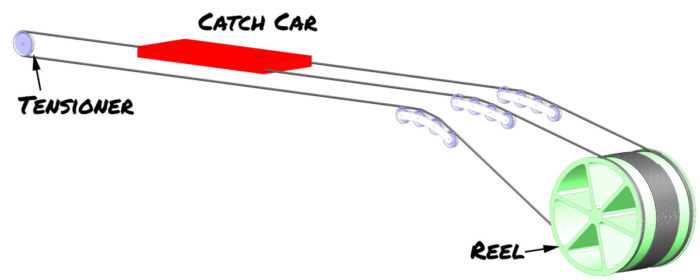
During launch, the reel will turn clockwise pulling the catch car and train to the right. The retract cable is unwound from the bottom of the reel at the same time. The tensioner sheave slides left to keep the cables tight.
Generally speaking, wire rope cables are designed to hold 4x the anticipated load, so we would need a cable with a 96,000 lb breaking strength. Also important is the diameter of the sheaves (pulley) the cables are wound on. A good rule of thumb is the diameter of the sheave should be 20 to 30 times the diameter of the cable. The sheave we can see under the train is about a 1″ cable and about 20″ sheave a (20:1 ratio). I estimate these values from several feet away so I might be off.
Cable Tensioner
The cables need to be tensioned to operate properly. If the cables go slack, the ropes will not wind and unwind properly. This could potentially lead to the cables getting tangled or catching on something they shouldn’t. At best, this results in ride downtime. It will most likely result in major structural damage.
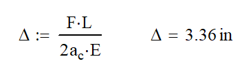
So the next plan is to tension the system and leave it alone. Wrong! Unfortunately, we are applying a very high load for a short time. The cables are going to stretch a lot. Using the formula below for calculating axial deformation (stretching). We find that in an active cable length of 450 ft, we would expect about 3.4″ of stretch at launch.
With cable stretching of this magnitude, we will need to do something more active to keep tension on the system. This is really nothing out of the ordinary. A chain or cable lift hill will also have a tensioning device. Most use weights because of the need for a quick response to changing tension and lack of maintenance. Check out this video if you want to know more.
A traditional weight could be used in this application, but the low distance to the ground creates a challenge. There are 3 possible paths forward; all of which use a sliding tensioner. These are springs or either hydraulic or pneumatic cylinders.
Using springs is the least likely scenario. While they would be the cheapest and lowest maintenance solution, they pose a large problem when maintenance needs to be done on the cable system. To properly tension the cables, you will need to have lots of stored potential energy in the springs. To safely work on the cables, you will want to remove this tension first. The other issue with springs is that they do not provide a constant force as motion occurs. This means that when the cable is longest, there is little tension on it leading to possible slack.
Top Trill Dragster Tensioner Sheave
Using a pneumatic or hydraulic cylinder solves the problem of constant force on the cable, provided there is enough pressurized fluid available. Let me explain. When quickly lowering a load on any hydraulic system, we can run into a situation where the volume of replacement oil needed is more than the system can deliver. This happens because gravity is lowering the lift faster than desired. When this occurs, the pressure of the fluid goes to 0 psi and no tensioning occurs. This is called overrun and it is bad.
In order to solve the overrun situation on the tensioner, we need to have a large amount of hydraulic fluid or compressed air ready to fill the cylinder at a high flow rate. The best way to do this is to have an accumulator tank nearby with a large hose running to the cylinder. An accumulator is basically a storage tank of pressurized fluid that is able to accommodate large changes in volume over short amounts of time while keeping the pressure fairly constant. You most likely have one of these in your house called an “expansion tank.” Check out this article for more information.
At the heart of the cable system is the giant 7 foot (2.1 m) cable reel where the cables are wound. As launch occurs, the two top cables will be winding onto the top of the reel. A third cable, which pulls the catch car back will be unwinding from the bottom of the reel. The reel will need to turn 20.5 times in the 3.8 second launch with a top speed of 540 rpm
The two cables on the top launch the train while a 3rd cable unwinds to pull the catch car back.
Sweet video of the reel while launching.
The drum has an external tooth gear on each end where 16 hydraulic motors are attached for a total of 32 motors providing power. Many think that this is a planetary gear system, but it lacks the internal tooth ring gear. In effect, it is one sun gear powered by 16 planet gears.
You will also notice the sound the gears make in the video above. This sounds like my 2000 Saturn SL when I back up. The sound is caused by straight cut (spur) gears. If the gears were helical, where the tooth angles across the face of the gear, the reel would run much quieter.
Total Horse Power
This is actually the wrong question. While spouting off a number might sound impressive, it is irrelevant. I compare it to sizing a light bulb. For so long, we sized light bulbs in watts, but that is not a measure of light, but power. Since compact fluorescents and LEDs came along using far less power, we now have to switch over to how much light or “lumens” the bulb creates. For most of us, this is a totally meaningless number.
Power is a function of Force and Velocity (must be in the same direction). At the speed and weight given, the peak horsepower of the train is 15,300 hp (11.4 MW). However, this power is only at the very last moment before the train and catch car separate. For the initial moment of launch, the power is 0 because there is no motion.
To further illustrate my point, I could power a launch with only one of the 500 hp engines, but it would extend the launch through Gemini and off the end of the island. Not very exciting.
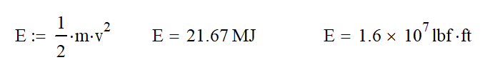
A better way to measure this to look at the energy in the system using the following equation to see that the train has 16 million pound feet of energy. Unfortunately, to most of us, this is a meaningless number.
One more thing to keep in mind here. We have not considered efficiency thus far. Generally speaking, there will be a 15% energy loss in the mechanical system. This is from friction of the cables as the drag on the rollers, the internal stresses of cable flex around the sheave and the rolling resistance of the train.
The hydraulic system may only have a maximum efficiency of 70% At high pressures, pumps and motors are hard to seal and they leak internally which is a loss of efficiency. The main loss is in the accumulator. When pressurized, the nitrogen creates a lot of heat which is released suddenly at launch. The heat radiated from the accumulators is never recovered. This would mean that it might actually take around 25,700 hp to launch the train.
Hydraulic System
As a Certified Hydraulic Specialist, Top Thrill Dragster makes me happy. It has the largest hydraulic system I’ve ever seen. There are 4 identical systems each having a 500 hp engine! The maximum pressure of the system is 300 bar (4350 psi).
Attached to the engine is a pump that constantly provides pressurized hydraulic fluid. When the ride is not launching, the pumps are resetting the catch car and pressurizing the large accumulators. The accumulators used here are piston style; you can imagine these as a cylinder with no rod. Hydraulic oil is on one side and pressurized nitrogen is on the other.
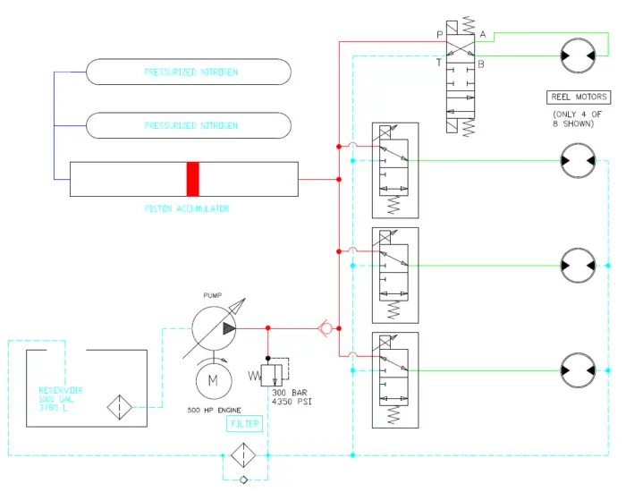
Top Thrill Dragster (Unofficial) Schematic. There are 4 identical units required for launch.
The accumulators are a critical part of the design. For the 45 seconds between launches, pressurized hydraulic fluid is stored here waiting for launch. This ride would not function as it does without them.
A piston style accumulator is definitely the right choice for this application, because it allows for easy expansion of the nitrogen gas. In this case, we can have the accumulator go from all the way full (piston at left) to all the way empty. In a traditional accumulator, there will always be some gas in the accumulator.
Having the pressurized nitrogen in separate pressure vessels leads to lower costs and easier placing of components (it doesn’t have to be in one really long component). Most importantly, it allows the pressure to be more even regardless of piston position.
Launch
Once the accumulators are full, the system can launch. At this point, cartridge valves open using an electric solenoids. Fluid flows from the accumulator and pump to the 8 motors on each subsystem. Most of this flow is from the stored fluid in the accumulators.
One of the coolest functions of a hydraulic system is the fact that oil is nearly incompressible. This allows for accurate control of the output (train speed) of the system. I’m sure that there is a rotary encoder on the reel that tells the computer exactly what position the catch car is in and exactly what speed it is going. This means that the computer can adjust the flow to the motors if the train is going too fast or too slow.
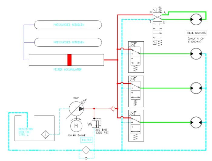
Valve positions at launch. Thicker hydraulic lines show the majority fluid flow.
At the beginning of the launch, there is no flow through the motors only pressure. This starts the rotation of the motor and reel. The flow will increase until the target speed is reached and the system will slow down. The pressure should remain the same for the entire launch.
To ease comfort for the rider, the control valves will be proportional. The computer will slowly open the valves at the beginning and slowly close them at the end. Once the train reaches full speed, these valves will start to close and the launch will stop.
Resetting the System
I’ll be honest here, I’m using my best guess on this section. As the catch car is moved back to the initial position, I believe that they use the hydraulic system to do it. Why would you want to introduce a new system here? The question is how.
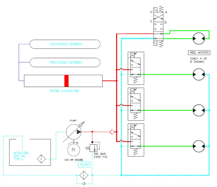
Valve positions for resetting. Only the top motor is used to reset. The others recycle the oil from the reservoir. Not using all the motors leads to faster cycle times on the ride.
Since there is not as much load to reset, you wouldn’t want to use all 32 motors to do it. That would be a waste of oil and would take much longer to get the system ready for launch. I speculate that only one motor per system reverses the reel. The rest of the hydraulic motors would free spin; recycling the oil from one port to another. This motor is also used to lock the reel while the others can free spin.
Rollback
One of the cool things about Top Thrill Dragster is that it can rollback if it doesn’t clear the top hat. Don’t worry, it is designed for that. As soon as the train passes, brake fins extend up to stop the train. These fins don’t actually contact the train, but slide between magnets located on the train. This phenomenon creates a magnetic field which creates an eddy current in the plate which resists the motion of the train. Since motion is required to create the current, the fins can never fully stop the train so another mechanism is needed to actually stop it.
One important thing to consider is that if there is a rollback, you don’t want the train to reattach to the catch car. That would probably destroy the ride and injure everyone on board the train.
The launch dog, mounted on car 3, is naturally held up either by spring or magnet so that it cannot make contact with the catch car. Before launch, you will hear a clang and then the train will rollback about 6 inches. The clang is caused by an electromagnet beneath the train pulling the launch dog down. Once down and engaged with the catch car, it is mechanically latched and the electromagnet deactivates.
Issues
As you can imagine, this is one complicated machine! It has it all: cables, wheels, hydraulics, giant spinning wheels, hundreds of sensors and a giant control system to go with it.
With each of these components and systems, there is a risk for malfunction which will shut down the ride. As you can imagine, this ride sees quite a bit of downtime. However, in the last decade, the maintenance team has become a well oiled machine and have been able to keep it running more often.
As the ride is nearing 20 years old, we hope that it will continue to operate for another 20 years! See you there.