

Steel design seems to be moving in the direction of self-fixturing where the weldment or assembly components will align with each other. When a tab or slot is added to a part, the stress flow is disrupted. These can lead to large stress concentrations. Tabs and slot joints should not be added in an already high stress area. Besides removing material, sharp corners in the slot can lead to high tensile stresses.
The reason self-fixturing has become so popular is that it removes lots of time from the assembly process. At a former employer, young manufacturing engineers designed a desk that was assembled using slot and tab design. The tabs had hooks on them so that once they were assembled, it would stay that way.
The design was pure genius: a desk that was made of laser cut sheet metal which could be completely painted in the powder coat system and assembled in minutes with a handful of screws. As a result, almost all desks on the shop floor where this design.
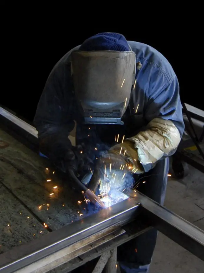
Self-fixturing has become very popular in welding as well. If components can fit together without external fixtures, there is a lot of time and money saved. If you can’t do self-fixturing, try having the fixture be self-fixturing.
Big Changes
Forty years ago, most components were cut in a shear press so designers could never dream of anything approaching tab and slots. It is only with the advent of CNC machining that self-fixturing is possible. New machines like laser and plasma tables or water jets have made this a reality.
Another change has happened just recently. In 2018, Solidworks added a “tab and slot” feature in the sheet metal menu. This allows the user to drastically speed up the process for the designer to add these features. Undoubtedly, this will lead to the proliferation of potential stress concentrations.
Did We Forget About Stress Concentrations?
Yes! Every tab and every slot carries several stress concentrations with it. The slot is most obvious with the 90° corners. But the tab can also have stress concentrations where it attaches to the parent material. These show up when the tab is in tension or bending on the weak axis.
The Battle
In every tab and slot design, there is a battle waging. On one hand, you have a tight fitting joint with only a few thousandths of play. With this you also have very small or nonexistent radii. Very large stress concentrations.
On the other hand, you have a loose fitting slot with radii that minimize the magnitude of a stress concentration.
As the designer, you will need to come up with a balance for this problem.
How to Properly Design Weldments: A Course for Engineers
Stress Flow and FEA
Unfortunately, stress flow is not something that can be easily taught in engineering school. It must be learned through years of practice. This is part of the reason that I am putting together a comprehensive course on stress flow available in the summer of 2020.
The common thought process for young engineers today is to shortcut the learning process by using FEA. There are at least three problems with this.
- FEA only shows you the result – It is important that the designer completely understands how stress flows. FEA is a very slow teacher and the lessons are forgotten quickly.
- The feature is left out – Most designers will leave these features out of the FEA model to speed up run time.
- Singularity – Most designers won’t spend the time to address the singuarity issue in the corners of the slot. FEA doesn’t handle stress making sharp angles well. If the FEA operator is not careful, the stress can be grossly underestimated or overestimated.
Not All Slots Are Equal
Longitudinal and Transverse Loadings
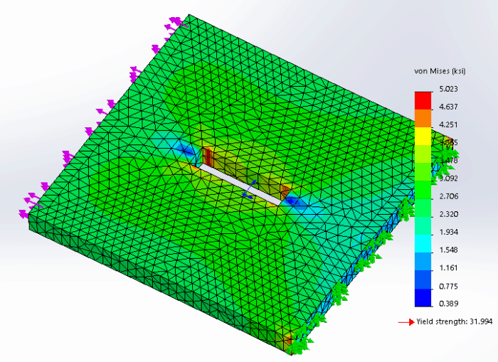
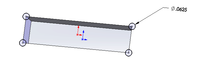
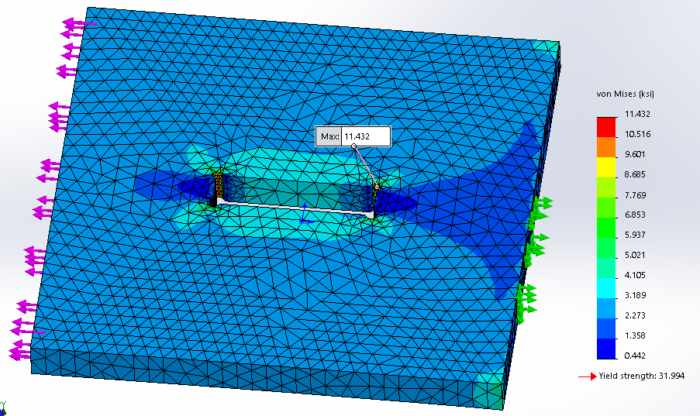
When adding slots, you will want to ensure that your slots are longitudinal, parallel, with the direction of stress flow. In the generic example below a plate is subjected to a 2000 lb load longitudinal to the flow of stress. You can see that most of the stress around 3 ksi. The peak load of 5 ksi occurs in the corners of the slot. The plot shows a fairly even distribution of load around the slot and through the material as a whole.
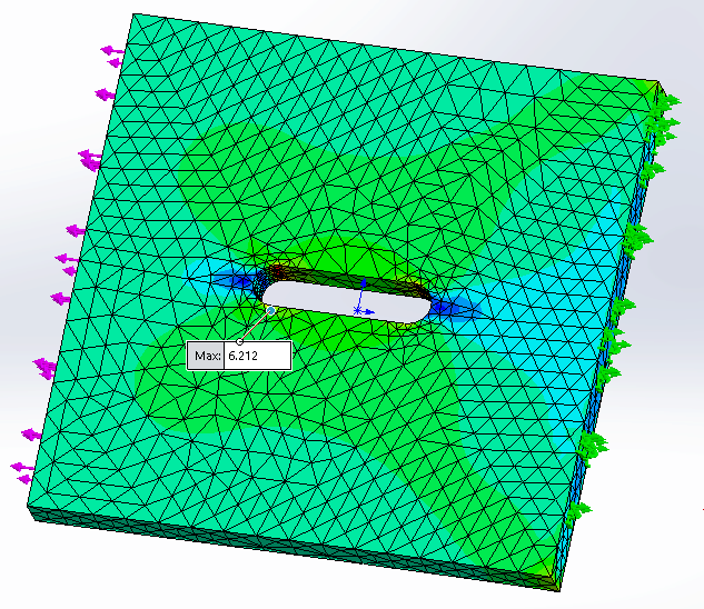
If we rotate the slot (or loading) so that the slot is now transverse, perpendicular to the stress flow, we get much different results.
Our nice, evenly loaded plate now has very hot and very cold spots. We also changed the peak stress to over 10 ksi! Twice as much as the longitudinal peak.
The logical conclusion is to avoid transverse slots as much as possible. It may be necessary to have two or more narrow slots instead of one longer one. As a rule of thumb, I would use the tabbed plate thickness as for the target slot width. This would make a square tab.
Radii Slot Designs
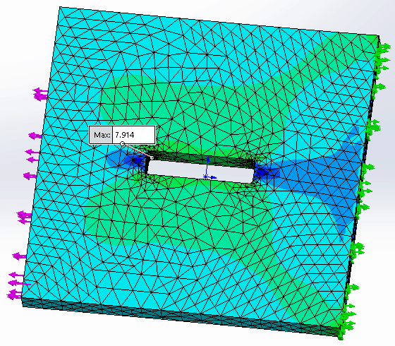
Adding radii in the corners of your slot are a must. This is where FEA and logic don’t meet up because of the singularity issue in FEA. Above, the maximum stress is 5 ksi, but when I add the radii in the corners, the stress increased to nearly 8 ksi.
In fact, as I add a tighter and tighter mesh, the stress will continue to increase. This is why FEA isn’t a good tool for evaluating stresses in some cases.
When adding radii, I recommend a radius of no less than 1/8 of the slot width. To ensure that the tab will not interfere with the radii, add twice the radius to the slot length. This will have a looser fit, but give more strength.
Full Radius Slots
My “go to” for slot design is the full radius slot. By increasing the diameter to half of the slot width, I can minimize the stress concentration as shown below. The other benefit is that I can accurately calculate the stress concentration because it is in most tables.
The major downside to this is that I lose even more lateral positioning accuracy. However, I have found in practice, that there are usually other parts that almost always add this accuracy back in.
The Dogbone
The Dogbone is a slot design that is used when highly accurate positioning is required. You will see this a lot in fixtures. This is usually used with a laser cutter because the tolerances are quite tight. A laser cutter will cut a very straight line, but as soon as it changes direction, you have imperfect corners. This is a problem in the corners of our slot.
The solution is to add a circle at each corner and then blend in with a radius. The radius will usually be equal to the corner radius.
As mentioned before, there is a battle between accuracy and strength. This slot profile is very accurate, but creates the largest stress concentration.
The dogbone slot finds its best use in the design of fixtures, but can also be used in low stress applications where high precision is needed.
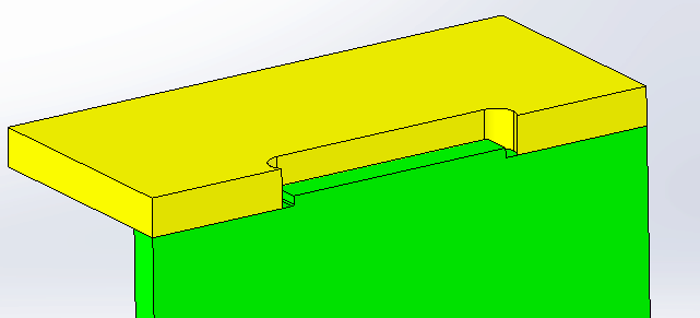
Tabs Aren’t Created Equal Either
Tabs are often overlooked for stress concentrations. In weldments where both sides of the plate are available for welding, it may not be an issue. However, in the case where only the tab is available for welding, there usually are very high stress concentrations.
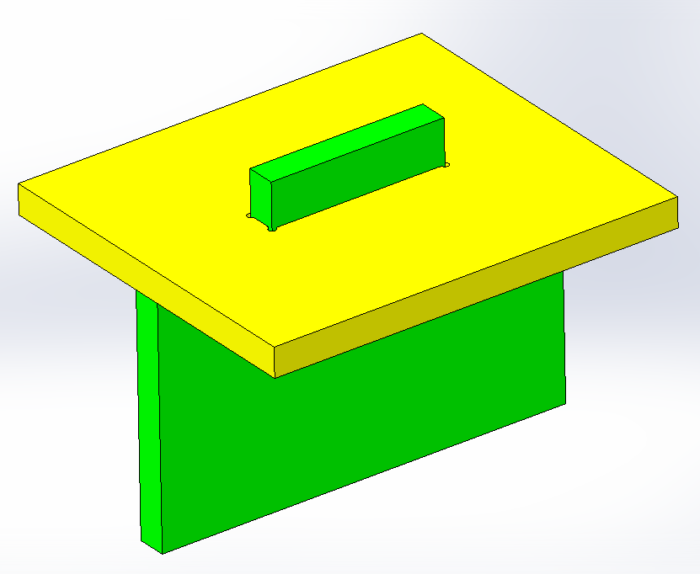
In fact, I don’t like to have tabs that stick all the way through the slot. Let me explain.
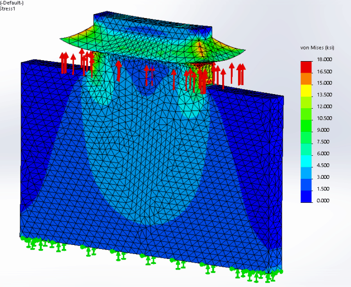
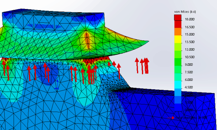
From the FEA plots above and below, you can see that there is an incredible stress concentration at the root of the fillet weld. This area is in tension and cannot be inspected. These are usually areas where fatigue cracks start.
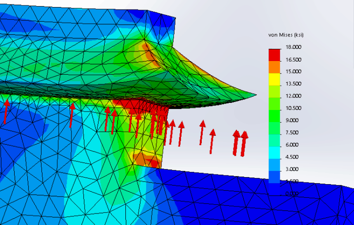
Many people like having this design because even if the weld does crack, it will leave enough welded material so that it cannot pull through the slot. This is foolish for two reasons. One, the wedging action will induce major stresses on the slot that could cause the slot to tear. Two, good engineers don’t design things that fail.
Here are two options that will make tab design much better.
Modified Tab
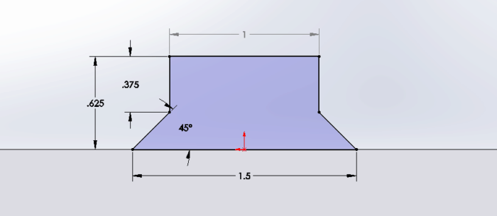
By modifying the tab to be larger at the base and smaller at the top allows for much better stress flow. As you can see from the design below, the base is 1.50 in wide. Over the thickness of the slotted plate material, it tapers at 45° to a tab width of 1″. In this case, the plate thickness is 1/4″. I like using 45° because it allows the top of the tab to narrow by twice the plate thickness.
When we look at the FEA for a plate with only the fillet weld, we can see that the stress concentration is still under the fillet, but the stress flow into the tab is much more consistent. This is a win because we are now directing the stress flow the way we want to.
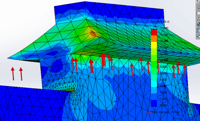
Now let’s take advantage of the cavity we just created by filling in the 45° taper with weld. That plug weld will give us a plenty of extra bonding between the plate and the slot and eliminates the stress concentration.
Minimal Tab
Even with the modified tab above, I have concerns about getting penetration deep into the bottom corners of the taper. My go to for a tab design is what I call the minimal tab. It offers the best joint for both the tab and slot.
As you can see below, the tab is very short in height and length. Usually it is less than 1″ long and 1/16″ high. It may need to be longer if the slot plate material is thicker than 1/4″ material.
By adding a plug weld in the entire slot, we ensure maximum penetration between the tab and slot. This fills in most of the slot with weld and removes most stress concentrations.
General guidelines for a plug weld is for the width to depth ratio to be greater than 1.5″. For example, a 1/4″ wide slot should have a maximum depth of 0.166″
Don’t Believe That Filling in Gaps with Weld is the Solution
So a common misconception is that filling in the slot will regain the full strength of the parent material. Not True! While is may be true in a few situations, an engineer should never rely on 100% penetration of a weld. Instead, you should assume that there is no penetration on fillet welds and as little as 70% on bevel or plug welds.
There are many factors that go into this. The laser cut can leave debris, contamination or hard spots on surface making a poor bond with the weld. The welder can be having an off day and not position the nozzle correctly or not have the part “in position”. Using the wrong wire material, having the weld gas off or incorrect settings can lead to a poor weld.
Of course, you can grind out or plasma cut a fillet weld, but it is very difficult to clean out the inside surfaces of a slot or a bevel. For these reasons, we should never assume that our welds will fill in all the empty space of a slot.
Watch for Interferences
As a final warning on your tab and slot designs, you need to watch for interferences. Most of these interferences happen because the radius is ignored on both the tab and the slot. If the radii contact each other, the parts won’t sit properly. The general habit of a fabricator (including myself) is to hit that thing with a BFH (Big [um] Freaking Hammer) until it fits.
Since the interference is most likely caused by radii in contact with each other, you have probably mashed the nice smooth radius into a jagged surface. You just created a much larger stress concentration than the one you were trying to solve.
Make sure that there are no interferences on the tab and slots. Most 3D CAD packages have an interference detection module that points these out quickly.
Further Study:
How to Properly Design Weldments
Why Fatigue Cracks Start at a Weld and How to Diagnose the Cause
In Summary
All tab and slot designs are large stress concentrations. Follow the following guidelines and you can expect much better results.
- Determine the prevalent stress flow on your slots, run your tabs longitudinal to that.
- If your stress flows transverse to the needed slot direction, minimize the length of the slot.
- Be aware of the battle between tightness of joint and stress concentration factor. One must be sacrificed for the other.
- FEA doesn’t give you the best results because it assumes 100% penetration welds and singularity is almost always an issue.
- In highly stressed areas, use a fully radiused slot and a tab with minimal heigh
- Add radii to all corners and watch the interferences.