

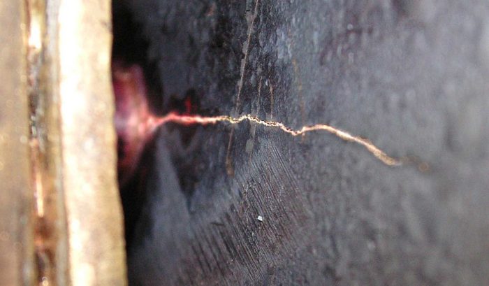
On many occasions, I have had to diagnose the cause of cracking. Many cracks started in the welds rather than the parent materials. I needed to find out why. Field fatigue cracks in weldments often start in welds rather than the nearby parent material due three causes. They are imperfections in the weld, poor joint design and residual stresses from the welding process.
If your welds are cracking within hours of welding, you do have a fabrication problem. The underlying culprit is trying to weld a material that has lead or too much carbon. The most likely causes are using incorrect welding rod material, not preheating, or cooling too fast.
If you are experiencing these types of cracks, consult an AWS Certified Weld Instructor for guidance.
Now, let’s explore each source of how weld cracks.
Residual Stresses
Every weld has residual stresses. These are stresses that form when the welds cool. It is what causes the parent material to deform in the process.
Let’s look at a typical example. If we have a Tee joint and add weld on each side of the web plate, the hot weld material will fuse with the top plate and cool. As it cools, the material contracts (reduces in size). The top plate tries to resist this and is put in bending.
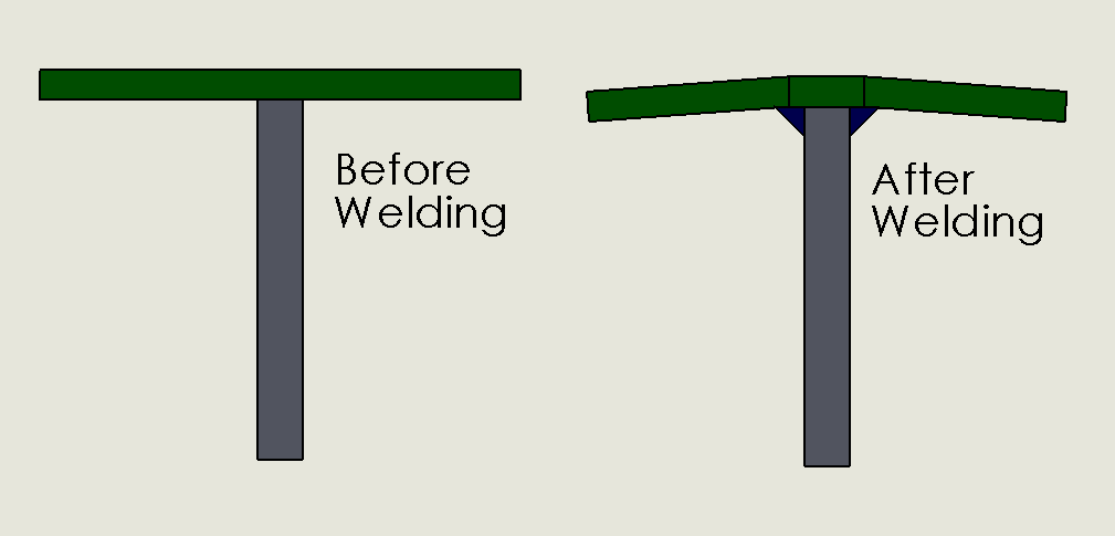
When the weld is finally cooled, the top plate has a residual bending stress in the top plate and a tensile stress in the welds. Because there is clear deformation in the weldment, these stresses have to be at yield.
How Ductility Plays a Part
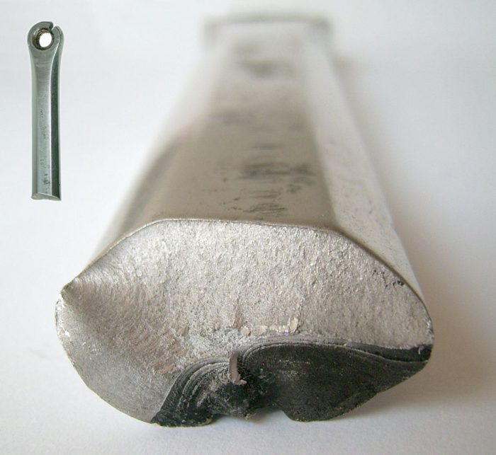
This occurs in every weld, it doesn’t cause widespread problems in steel because readily weldable steels have great ductility. Your higher alloy steel and aluminum materials are not as fortunate because their ductility is low.
In fact, I never recommend the use of welded aluminum in high impact or high fatigue cycle loadings.
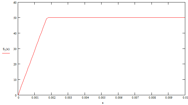
Let’s unpack this a little more. In an ideal ductile material, this is what the stress strain curve would look like. There would be the steep sloped linear region quantified by Young’s Modulus. After that, it would transition to a horizontal region where the material would stretch without the addition of more load. At some amount of strain it would fail.
So at this point, you should be scratching your head as to why ductility matters.
Classical stress analysis assumes linearity. If we assumed that there were no residual stresses in the material, we would assume that additional load translated into additional stress.
This is not the case for welding. As mentioned, our welds start out at yield stress. If our weld material is already at yield and we now load it up to the machine’s maximum induced load, we are going to be operating in the horizontal area of our stress-strain curve. This means lots of strain, but not much change in stress.
When the load is released, the material behave according to the Young’s Modulus and the stress will lower below yield.
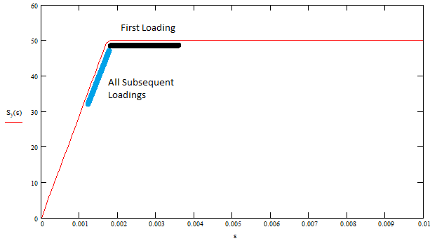
Let’s work an example to hammer in this point. Let’s assume we have a Tee joint of 50 ksi yield strength material. After welding the material, the welds will be at 50 ksi by definition. This is the residual stress.
If we induce a load through the welds of 15 ksi, the first loading will not show and increase in stress. The stress would still be at 50 ksi in an ideal ductile material. As we release the load, the stress will follow Young’s Modulus and reduce to 35 ksi.
Every time the load is applied, it will increase to 50 ksi and return to 35 ksi.
Why the Crack is Likely to Start in the Weld
While the stress in weld is elevated, the stress in the parent material is operating according to classical stress calculations with a low of 0 ksi and a high of 15 ksi.
The mean stress is a large component in fatigue calculations. The higher the mean stress, the lower the alternating stress can be.
As we look at the mean stresses in the parent material vs the weld material, we can see a drastic difference. The parent material has a mean stress of 7.5 ksi [(0 + 15 ksi) / 2]. The weld material has an average stress of 42.5 ksi [(35 ksi +50 ksi) / /2]. What a difference!
Both have the same alternating stress of 7.5 ksi, but with the drastically different mean stress. The weld is much more likely to crack first from fatigue. It will take far fewer cycles to crack the weld than the nearby parent material. This is the main cause for cracks to start in a weld.
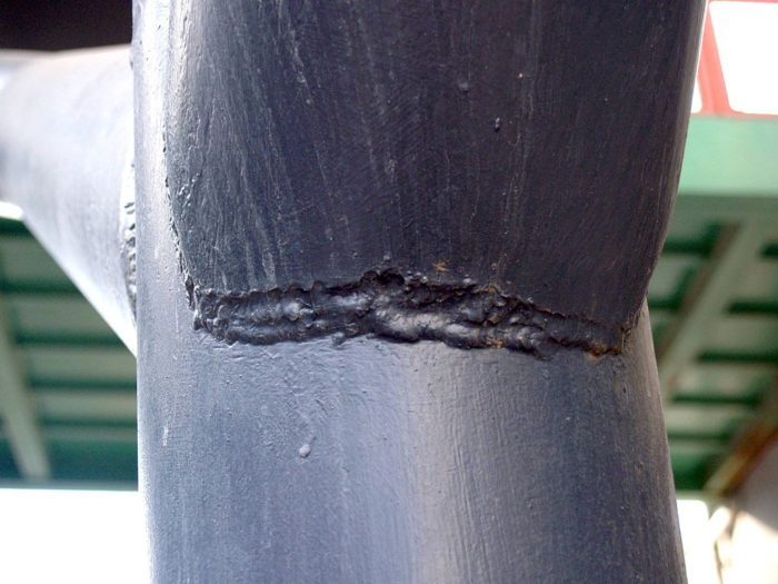
Lokilech / CC BY-SA (http://creativecommons.org/licenses/by-sa/3.0/)
One thing to keep in mind is that this design has a 3.33 design factor in it. For most steels, this is way over designed and fatigue should be the furthest thing from our mind. However, fatigue is an issue simply because the residual stress in the in the weld.
Reducing the Residual Stress
One way to get your stresses away from yield is to overload the unit the first time it is operated. Many times, tests like these are required which is cool because it works to our advantage.
As you saw before, when the unit was loaded the first time, it only saw strain and not additional stress. At the end of the loading, the stress was reduced from 50 ksi to 35 ksi.
Now imagine that we had to load up to 1.5x the working load and the applied stress increased from 15 ksi to 22.5 ksi. This means that the structure when relaxed is 27.5 ksi and not 35.
Overloading helps us improve the life of the welds by lowering the stress levels away from yield. This loading doesn’t have to be the absolute first loading of the machine. The closer it is to the beginning of the machine’s life the better.
Imperfections in the Weld
The most obvious cause of fatigue cracks in weldments is poor workmanship. This can be caused by a variety of causes including:
- Poor root penetration
- Excessive undercutting
- Too high or too low voltage
- Too high or too low travel speed
- Wrong welding rod material used
- Porosity and other voids
- Incorrect welding technique
- Lack of Fusion
- Burn Through
Generally speaking, these are easy to spot visually and correct. The one exception is poor root penetration. This one usually requires destructive means to determine root quality.
If there is clearly a bad weld, this may be the only culprit. Fix it and move on. However, a good engineer should investigate to see if there are other underlying causes. There usually is.
Alu.cz / CC BY (https://creativecommons.org/licenses/by/3.0)
My general rule of thumb is if there is one unit that cracks and a weld defect is found, it’s probably just that. If a crack is found on two or more units, you have a deeper problem.
Poor Joint Design
Poor joint design is usually to blame for welds that continually fail. Many times joints fail because there is bad stress flow built in. When a weld cracks, it is likely seen as the suspect, but in many joints, it doesn’t matter how good your weld is, it is destined to fail.
Many engineers are not trained to identify good joints from bad joints. It is not something that is taught in school and needs to be learned. This is why I created my Advanced Stress Flow Course. This course is a must have for all engineers who design any type of structure.
Understanding how stress concentrations, balancing forces and weld angle affect the stress flow is essential. It breaks my heart when I see young engineers have the reflex to “Run a quick FEA” when a few simple calculations will give the same result.
Very valuable information. Thank you.
From Magnolia, Texas