Recent Posts

How to Select a Washer in a Fastening System

Selecting a washer for a fastening system is an important, but often overlooked step in designing a fastening system. Washers need to be selected based on the load in the joint, the materials in the joint and, as always, the environment.

Yellow Zinc Plated SAE Washers

Can a Washer Be Installed Backwards?  

Interestingly, the answer is YES: many people do not realize that washers can be installed backwards. 

I often get strange looks when I explain this to young engineers. They think that I am playing a joke on them.

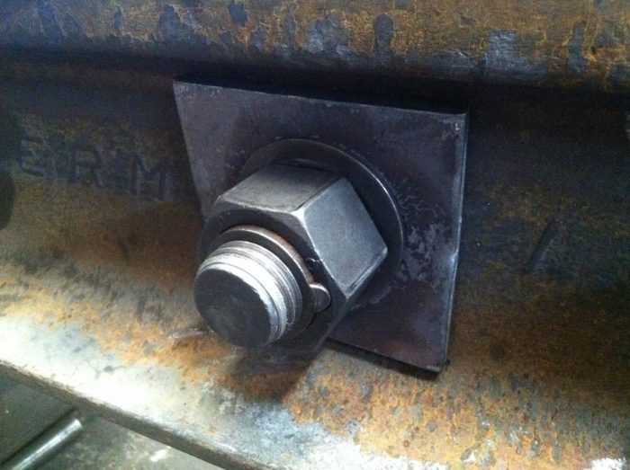
Since washers are formed from a stamping process, only one side will have a radius because they are only formed on the top leaving a sharp edge on the bottom.

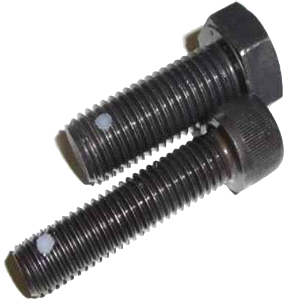
If I look at a hex bolt it will have a slight radius between the head and the shank.  We want to have the radii of the washer and the bolt mate. Having the sharp corner of a washer poking into the bolt’s radius can cause a dent which impedes stress from flowing from the shank to the head. This creates a large and unnecessary stress concentration leading to premature failure.

To tell which way the washer is to be installed, run your finger over the hole on each side. The side that is smoother has the radius and should face the head of the screw / bolt. It doesn’t matter on the nut side, but I usually install it with the smooth side facing out.

Washer Types

In general, there are several different styles of washers.

  • USS (Large, Wide or Type A) – Good for general use. Have a large outside diameter making them good for use with softer materials like wood, plastic and fiberglass. This is a good general use washer.
  • SAE (Narrow) – When fastening stiffer materials, like steel, this is my go to fastener. They are strong and smaller then the USS washer (both OD and ID). When using near welds or bends, you can get a hole closer with this washer.
  • Fender – These are huge washers that cover up imperfections, often used in sheet metal applications. These are thin compared to a USS or SAE washer so if you need to transmit a larger load, use it with a USS washer.
  • Split Lock Washer – These are washers that I have a slit cutout and are formed sprung open. When load is applied, they will flatten and keep the fastener in tension. These have a tendency to deform under high loads and are not recommended for structural joints.
Split Lock Washers
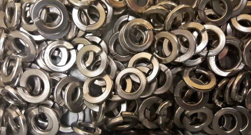
Image Courtesy of Needpix.com
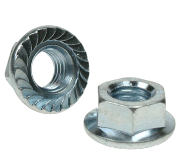
  • Serrated (Star) washers – These washers are great for sheet metal applications such as household appliances and grills. However, it is intended to scratch surface paint to lock in place so there will be corrosion. Not the best choice if you are using it outside on steel.
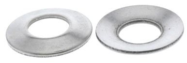
  • Countersunk or Finishing Washer – These washers are taller than the other washers because they are countersunk to allow the head of a countersunk screw to be flush when installed.

In my mind, this kind of defeats the purpose of using a countersunk screw in the first place. Countersunk screws are used so that there is nothing sticking up past the parent materials surface.

If the material is too thin too accept a proper countersink, adding this washer isn’t the solution. I would switch to a button head capscrew instead. This will eliminate the need for a countersink while giving the minimal amount of a head height.

  • Spherical Washer – This two part washer allows for angular adjustment if holes aren’t perpendicular to the fastener. Rather than adding a bending stress to the screw, the spherical washer adjusts so bending stresses are eliminated. A tolerance of 3° to 5° can usually be accommodated.
  • Bellville Washer – These magnificent creations are cone shaped washers are the split washer’s “big brother.”
Bellville Washer

A Bellville washer offers more resistance to screw loosening because when tightened, it flattens the cone.  These washers have other uses as well; I once designed a limited slip differential using a series of these. 

If you want more compression force, you can stack these as they would naturally stack.  If you want more travel, you can stack them so that the top of the cones touch.  You can arrange these in multiple ways so that you can get the system characteristics you want using standard off the shelf parts.

When Selecting a Washer Keep in Mind These Rules of Thumb

  • The softer the material, the larger the washer needs to be.
  • Have approximately the same stiffness for all components of the joint.

The Softer the Material, the Larger the Washer Needs to Be

It doesn’t take much insight to realize that a steel washer can easily be drawn into wood leaving an impression if over torqued. The same applies to plastics, rubber and fiberglass. Rubber and plastic is pretty forgiving, but an indentation in wood or fiberglass will cause the material to be weaker.

The solution to this is to increase the washer diameter. Wooden joints should have at least a USS washer. If possible, use a USS washer with a fender washer underneath to get the maximum amount of contact surface area.

Have Approximately the Same Stiffness for All Components of the Joint.

As your load increases, ALL the materials in your fastening system need to be equally as stiff. There have been major structural failures, like the Kemper Arena collapse in 1979, that were caused (in part) by fasteners bolting non-similar materials.

Bolting steel with rubber, plastic, and / or wood for a load bearing structure is not recommended. If non-similar materials are used, fastener load can fluctuate with applied load, weather, humidity etc. leading to loss of preload and increased fatigue load.

The Kemper Arena failed because 1 of 4 bolts in a pattern that was repeated throughout the structure lost preload. This caused the remaining bolts to take the load, but it also added a prying action that was unintended. This overloaded the remaining fasteners and eventually caused the ultimate failure.

Washers are available in both hardened and non-hardened materials.  It is important to match high strength bolts to high strength washers.  In practice, you may want to have a hardened washer if the washer has a large hole to cover or spans a slot. 

Environmental Concerns

When considering a washer, we have to be concerned with not only the corrosion protection of the washer, but also galvanic corrosion between the materials.

Galvanic Corrosion

Galvanic corrosion exists between dissimilar metals as small currents of electrical energy are naturally created. (This is what makes thermocouples work.)

If we have a fastening system of zinc washers and cadmium plated steel bolts and nuts fastening aluminum to steel, we are going to see that the contact between: zinc and steel; and cadmium and steel will be subject to degradation due to galvanic corrosion.

However, there will be almost no interaction between the aluminum and cadmium and only mild interaction between aluminum and zinc or steel.

There is a lot more to cover here which I will do in a future article. You can read more here for now.

Recommendations

My first recommendation is to make sure that the bolt, nut and washers are all the same type of material and have the same plating.

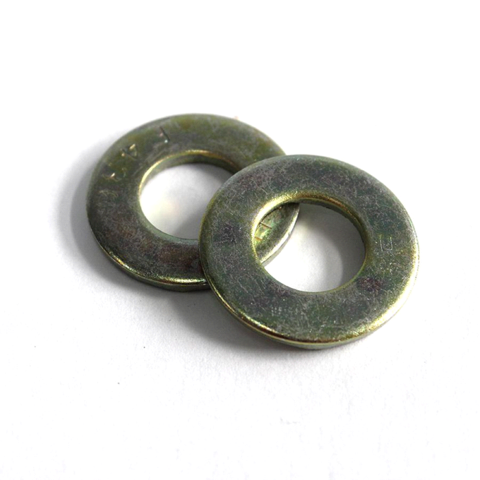
For a long time, zinc has been the go-to material, but it doesn’t offer a great resistance to corrosion.  The next bump up is zinc with added trivalent or chrome to increase the salt spray life.  You will find this “white zinc” plating on most fasteners in your hardware store. They rust quickly, avoid these where possible.

My next plating recommendation is the hexavalent chrome version, also known as “yellow zinc”, offers far better protection (like 3x), but it has landed on the RoHS list and will be impossible to get in the next few years.  You may remember that the movie Erin Brockovich was about the use/misuse of hexavalent chrome (it’s a good movie, I recommend it)!

Conclusions

Selecting the right washer for your application depends first on selecting the right type of washer for your materials and application.

You’ll want to keep all of your fastener materials and plating the same to maximize life span.

You will also want to maximize the contact surface area for softer materials by using USS and / or fender washers.

Finally, removing soft materials from structural joints so that preload on the fasteners can be maintained.

Easy Guide to Selecting the Spider and Jaws for Shaft Couplers

This post is a continuation of a how to determine the torque needed for our coupler. Click Here to view it.

Jaw type shaft couplers are a lifesaver. These wonderful pieces of machinery allow for torque transmission between two different items and account for radial, angular and axial misalignment. It also has built in shock absorption that diffuses impact loads, like from reversing loads, and start up loads.

Jaw shaft couplers do this by having a mechanism, the spider, to connect two jaws. One Jaw connects to each shaft and the spider slips between the jaws. Great reasons to use jaw couplers include the following:

  • Allow for some misalignment (let’s face it, it is tough to get shafts to align right!)
  • Thousands of options for shaft size, torque transmitted and spider material
  • No metal to metal contact
  • Resistance to dirt and oils
  • Nearly maintenance free
  • Smaller sizes are readily available (no 8-12 week lead times). You can even buy them on Amazon.
  • Fail-safe. If the spider fails, the jaws will still make contact with each other. There will be metal on metal contact there, so be sure to replace the spider when this happens.

Spider Materials

The spider gets it name from its shape…sort of. Obviously, the legs on it look like a spider except for one thing. Spiders have eight legs not six! Insect may be more appropriate, but spider sounds much cooler.

L90 Urethane Spider

Selecting the right spider material is imperative. It must be able to handle the torque applied and provide adequate shock absorption.

It is also important to consider operating temperature. Be sure to keep in mind if the local temperature of the coupler will be higher than the ambient temperature.

A general principle when selecting a spider material is that you are trading shock absorption for torque. A rubber material will definitely offer more shock absorption, than bronze, but bronze will handle much more torque. Let’s take a closer look at the most popular materials:

NBR Rubber

  • This common material is used in almost all hydraulic and plumbing seals.
  • Inexpensive
  • Readily available
  • Highly flexible
  • Oil resistant
  • Great shock absorption
  • Good temperature range of -40° to 212° F (-40° to 100° C)

Urethane

  • Has 50% more torque capacity than NBR
  • Good resistance to oil and chemicals
  • Good shock absorption
  • Operating temperature range of -30° to 160° F

Hytrel

  • Flexible
  • High torque
  • Greater operating temperature range of -60° to 250° F (-51° to 121° C)
  • More expensive

Bronze

  • Highest torque rating
  • Available in oil-impregnated metal
  • Very low speed (keep below 250 rpm)
  • Very little shock absorption
  • Not affected by water, oil, or dirt
  • Highest operating temperature range: -40° to 450° F (-40° to 232° C)

Selecting the Spider and Jaws

Continuing from the example in the previous post, we will use the 5 HP engine running at 2500 RPM and came up with 126 in-lb. of torque. Our service factor was determined to be 1.5 bringing our required torque to 190 in-lb.

Sizing the Spider

It is easier to select the spider first and then the jaw set. Looking at the table below, I can choose:

  • L095 for NBR
  • L090 for Urethane
  • L075 for Hytrel or Bronze. 

Because Hytrel and bronze are the most expensive and least flexible alternatives (not to mention that the speed is too high for bronze), I will not consider the L75 as viable options.

The choice is now down to NBR and Urethane.  If I choose NBR, I will pay more for the jaws, but less for the spider.  The main benefit that I see is the urethane has a higher torque rating (216 in-lb.) at the smaller size than the NBR has at the larger size (194 in-lb.).  This will lead to increased life of the spider.  In fact, it may never need to be replaced. 

With all of that said, I will select the L090 with the urethane spider.

We will go ahead and select the actual part numbers we need. Remember, we have determined that the coupling size will be the L90 series. Now it is time to find the spider type that fits our application.

I prefer to use a type with an open center so that the shafts can go into the space that the spider occupies if needed. Looking at the listing we will need to find the Urethane (open center) spider type and then the intersecting column under the L90 coupling size. Where these two meet we find our part number which in this case is 11075.

Real World Update

Since I inherited the log splitter used in this example, the existing coupler was an L90 size, but with a NBR coupler. This was enough to handle the torque without the service factor.

It wore out and you could hear the metal on metal clicking as a clear identifier of the problem. I have replaced it with a urethane L90 coupler. Time will tell if it ever needs to be replaced again.

Selecting the Jaws

Now we can find the jaw part number needed for our application. First off, we need to know what shaft size is appropriate.

Our pump has a 1/2″ bore shaft size, we will want to match this up in the part listing. Looking at the chart, we will find where the L090 series column and the 1/2 bore with keyway intersect to locate the part number 26087.

Notice that we have a keyway on this which is 1/8 wide and 1/16 tall. Normally the height will be one half of the width for the keyway so that a standard square key can fit.

We will do the same for the other shaft which has a 3/4 inch bore size and keyway will 3/16 wide by 3/32 tall. Referencing this size on our chart, we find the L090 column and the part number which will be 10773.

After determining and selecting which parts are needed, we will need to go ahead and place an order for:

  • L90 Urethane Spider 11075
  • L90 Jaw with 1/2″ keyed – 26087
  • L90 Jaw with 3/4″ 3/16 key – 10773

I will mention that a great benefit of Lovejoy couplers is the presence of product distributers on Amazon. This makes the ordering process easier and the shipping faster.

Final Thoughts

Finally, I would strongly recommend applying anti-seize to all parts before assembly in order to prevent rusting. This is a huge help if you ever need to take them apart (at some point you will) and it is nearly impossible to do without breaking parts if rust has occurred.

For example, I recently had to do this on a project and ended up having to cut a gear in half to remove it from the shaft. Make sure you take this simple step to help prevent the hassle of rusted parts. In the end it will help preserve the parts and aid in the process of disassembling if ever needed.

I hope this information has been helpful in the process of selecting the right parts for your own project.  The intent of this article is to familiarize you with jaw couplers, be able to calculate the torque and service factors and finally be able to select the jaw size and spider materials right for your application. 

Happy designing!

(All images/charts courtesy of Lovejoy Jaw Type Couplings Catalog)

How to Determine Torque Ratings of Shaft Couplers

Jaw type shaft couplers are a lifesaver. These wonderful pieces of machinery allow for torque transmission between two different items and account for radial, angular and axial misalignment. It also has built in shock absorption that diffuses impact loads, like from reversing loads, and start up loads. Jaw shaft couplers do this by having a mechanism, the spider, to connect two jaws. One Jaw connects to each shaft and the spider slips between the jaws.

Great reasons to use jaw couplers include the following:

  • Allow for some misalignment (let’s face it, it is tough to get shafts to align right!)
  • Thousands of options for shaft size, torque transmitted and spider material
  • No metal to metal contact
  • Resistance to dirt and oils
  • Nearly maintenance free
  • Smaller sizes are readily available (no 8-12 week lead times). You can even buy them on Amazon.
  • Fail-safe. If the spider fails, the jaws will still make contact with each other. There will be metal on metal contact there, so be sure to replace the spider when this happens.

Determining Torque

The first thing that we must do in selecting the proper jaw type is to calculate the torque and application service factor. Torque is relatively easy and straight forward to calculate. It can be done with the following formulas.

Pretty simple.

Service factor

Now that we have this, we need to look up the service factor from the manufacturers chart.  Simply multiply the calculated torque by the service factor to get the torque needed to size the jaw.  The service factor is an essential element that accounts for impact loads that will be seen on the coupler.

Example of Typical Service Factors

For example, something powered by an electric motor will generally have a lower service factor than one powered by an internal combustion engine.  In single cylinder 4 stroke engines, every other rotation contains an impact load when the cylinder fires so there will be lots of torque for a brief moment.  Electric motors have much smoother operation. 

Every manufacturer has one of these charts. Look for two or three cases that describe your application. If they have different service factors, always pick the highest factor.

The reason for this because is while it a much better position to difficult to justify upfront costs if you can avoid future failures. Field failures are costly; there is lost production, diagnosing, engineering and fabrication costs, etc. that need to be considered.

Generally speaking, when a field failure occurs, there is way too much labor put in to solving the problem which adds up quickly and leads to a lot of costs. It gets worse if you are mass producing this item, because you may now have to add in the costs of field repair or worse, the cost of lost customers. So please, size it to the larger service factor.

Once you have the required torque value, you are ready to select your spider and jaws.

Learn how to Select the Right Spider and Jaw Set

Application Example

In my world, things without a practical application are worthless. So, I wanted to use the log splitter power train as an example.

The power source is a basic Harbor Freight 5 HP gas engine that will meet our needs.

Even a Harbor Freight engine should last for years if given proper maintenance and kept covered so that exposure to moisture does not get inside and cause it to rust. These few steps can help you extend the life of a motor and save you money in the long run.

Our pump is a Haldex two stage gear pump with a ½” keyed shaft. Right off the bat, we are going to need something to handle the difference in shaft size. A jaw type coupler will be perfect because we can use two different jaw parts.

Ok, let’s get started. I have had great success using Lovejoy L series couplers for applications such as these. We first need to size the jaw part of the coupler and we do this by calculating the torque. We will use the 5 HP engine running at 2500 RPM and come up with 126 in-lb. of torque required.

After finding the nominal torque, the next thing we want to do is make sure we are using the correct service factor. This is an added design factor based on the application.

Looking through the Jaw Application Service Factors guide we do not find a listing for hydraulics. Instead, we will need to find the section where we can locate the proper pump. For this application, we will be using a Rotary Gear Vane Pump and will want to use a higher service factor. In this case, I am going to go ahead and use the 1.50 service factor which will bring our torque to around 190-inch pounds.

Typical Services Factors for Jaw Couplers

Happy designing!

Learn how to Select the Right Spider and Jaw Set

(All images/charts courtesy of Lovejoy Jaw Type Couplings Catalog)

How to Count the Coils on a Compression Spring

Springs are essential to life. In fact everything on the planet acts like a spring, which follow Hooke’s law (F = k *x) . When force is applied to an object, it will deflect. If more force is applied, it will deflect more.

Count the total coils of the spring starting at one end and move toward the other end. This number does not have to be an integer. For an Open spring, this is the number of active coils. For a Open and Ground spring, subtract 1. For Closed or Closed and Ground, subtract 2 to get the active coils.

Counting the number of coils on a compression spring can be tricky.  There are two variables that specify the number of coils.  The value Na is the number of active coils and Nt is the total number of coils.  Only in the case of an open spring is Na equal to Nt.

Counting the coils in compression springs are tricky because not all of the coils count. First of all, you cannot count any coils where the coils are closed or touching.  These are inactive coils which don’t allow the spring to be a spring. 

The image below has common compression spring end types. The most common spring type is closed and ground which allow for stacking and even load distribution. The disadvantage is they take up more space.

Start counting each coil from one end to the other, starting where the section first opens.  (Indicated in image above) For an open end spring, this is the first coil.  Keep counting until you get to the other end of the spring.  Generally speaking, coils are counted as full turns, but half and quarter turns are also widely used.  Many spring manufacturers will allow two digits of precision on the number of coils.  For torsion springs, like clothes pins, you will specify the end condition in degrees.   

In the examples shown, each spring has 6 coils even though the closed end spring has 8 total coils.  The table below shows the relationship between active coils, total coils, the solid height and the pitch of each spring type. 

Note: It is customary to allow a 3% tolerance on the solid height of the spring to account for the end conditions, wire diameter tolerance and helical wind waviness.

How to Select the Right Type of Lock Nut

Nuts are the basic counterpart to bolts and screws. Most folks do not realize that nuts have grades just like screws. Typically, these grades will be stamped on the nut and need to match the corresponding bolt grade. For instance, if I take a grade 8 screw which will be between Rockwell C33-C39 the nut will be between C24-C36.

The highest selling screw is grade 8. Unfortunately, not many designers know that grades need to match because the highest selling nut is a grade 5.

The distribution of load on the nut is important as well. In general, the load is distributed on the first four threads of the nut.  This means that a structural nut needs to have at least four threads of engagement.  If the nut is the wrong grade, it will take more threads to distribute this load.  A standard nut does not account for this.  Match your Screw and Nut grades. 

When mismatched grades fail, it will look like the nut is trying to be rolled inside out until the screw can no longer engage the internal threads.

Types of Lock Nuts

Making sure a thread will stay engaged is essential to a good fastening system.  Locking nuts provide a great mechanism to do this, but there are other options we will discuss.

Serrated Flange Nut

The first type is a serrated flange nut, which, when tightened has ridges that grab onto the parent material, providing a locking effect. However, these can cause issues with rust as the teeth lock onto the material scratch away paint or other coatings.

Unlike the others, it locks onto the mating surface and not the bolt. For this reason, it is not recommended in high vibration applications. Finally, never use these with a washer underneath.

Nylon Insert Lock Nut

The next type is a nylon insert lock nut or ‘nylock’ which looks like a regular nut, except for the crown on the top of it. The blue part shown is a piece of nylon and it is inserted into the crown.  When the bolt is inserted, it interferes with the nylon causing it to lock the nut in place.

In all honesty, I do not like these nuts because if you use an impact wrench or nut driver that tightens quickly, it will melt the nylon and make it impossible to remove the nut.  Well, you can cut it off…but you get my point. 

At this point, it is impossible to check the torque on the bolt because you are only testing how well the nut is attached to the bolt. If the nylon and screw do become fused together, your joint may become loose over time.  Unless you can see a washer move, there will be no way to ensure the fastener is under tension.

These fasteners are not reusable.

Oval / Distorted Thread Lock Nut

So my preferred locking nut is an ovulated (oval) lock nut.  This is a standard nut where the top of it is squished to provide the locking mechanism.  The most common is to have the squish (yup, technical term) on the top, but it can also be in the middle.  The oval nut overcomes the deficiencies mentioned earlier with the nylon lock nut.  It also doesn’t interfere with the torque required to get proper clamping load, but you will need wrenches instead of your fingers to get it snug.

Unfortunately, these nuts are not reusable either so throw them in the trash if you need to replace them.

It is also important to note that the nut must always be a softer material than the screw. If the nut is harder, it will destroy the threads on the bolt. This will strip the bolt before it locks onto the fastener. For this reason, you should match metal types when using this type of lock nut.

Jam Nuts

Jam nuts are just regular hex nuts but not as thick. They are used by applying a standard hex nut on the bolt and apply the desired torque. Then screw the jam nut behind it. Holding a wrench on both the standard and jam nut, torque the jam nut to 1/4 to 1/2 of the torque on the standard nut.

Jam nuts are one of my least favorite locking methods. In high vibration situations, the nuts can easily break apart and possibly fall off. They are good solutions for tie rods in steering axles so that the alignment can be changed without disassembling multiple parts.

Another reason, I stay away from them is they require a longer bolt length. I’m paying for more for the bolt and the extra jam nut.

Castle Nut

Another type of lock nut is the called the Castle Nut. These feature a taller nut with recesses, usually six of them.  The intent is to tighten the nut until it lines up with a cross drilled hole in the recesses.  A cotter pin is then inserted, preventing the nut from ever backing out.   This nut also has a few short-comings.  First, there is increased cost with cross drilling the hole in the fastener and it requires additional time assembling. 

The main reason I don’t like them, is there is a good chance that when this is at the proper torque, the hole and recesses will not align.  You will either need to over torque or under torque.  This problem can be eased by using fine threads instead of course threads. I would consider using a castle nut only if it was an application where the fastener could be loose but cannot come out.

Locking Mechanisms That Don’t Use Nuts

Micro-encapsulation

There are several locking systems which can be used alone or in conjunction with other mechanisms. A common one is called thread locking or micro-encapsulation.  A locking compound, usually nylon is placed onto the screw itself. This type mechanically locks the fastener by pressing it against the side of the tapped hole. With these, you can torque them about three times before the patch is worn out and the fastener needs to be replaced. 

Thread Adhesives

Another type of thread locking method uses an adhesive.  A chemical adhesive is applied to the threads of a fastener just before it is installed and torqued.  These fasteners need to be installed in a certain amount of time before reapplication is need. There are many different adhesives used and then are available in both permanent and semi-permanent formulations with the latter allowing you to re-torque the bolt.

The Best Guide to Building a Backyard Roller Coaster

Since I was a young kid, I’ve been fascinated with roller coasters. I have build many functioning model and Lego roller coasters over the years. In fact, after a trip to Six Flags Magic Mountain, I decided to build my own!

While that attempt didn’t work well (sorry Emily), I did go on to become an engineer and know a lot more about the mechanics of roller coasters.

https://youtu.be/wxaVr74OMLE

Now that my kids are older, they are starting to share my love of roller coasters as well. So I thought, why not build one for them…..(and me) to enjoy in the yard.

I also wanted to expand this to everyone else by showing you exactly how I will be designing and constructing all aspects of the roller coaster.

And so, planning began on a backyard roller coaster named the “Black Widow” (My kids have a sudden love of spiders.)

As with most things, I stand on the shoulders of giants! There have been many other backyard roller coaster enthusiasts out there who have paved the way for me. I would like to point out Paul Gregg as a backyard roller coaster researcher who has opened the door to many non-engineers creating their own back yard roller coasters.

I wanted to share this channel playlist with you in the video link below. Enjoy!

Black Widow Roller Coaster Image Gallery

Learn More!

Please subscribe by entering your email on the right. This will keep inform you when new videos are released.