Planetary gear systems can be intimidating to understand. There are so many types of motions and reductions possible that it can be overwhelming.
The motion of planetary gear systems is expressed clearly in the Plantetary Train Equation: -S/R = (ωr-ωa)/(ωs-ωa). Once this is known, the speeds of the carrier arm, sun and/or ring can be calculated. Multiple series of planetary gear systems can be used to get multiple speeds and directions.
Planetary gear systems are used everywhere. Some examples are:
- Automatic transmissions
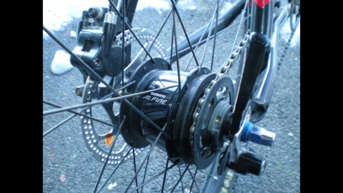
- Internal bicycle gearboxes
- Pencil sharpeners (I bet you didn’t see this one coming)
- Winches
- Hand drills
- Camera lens focusing
- Truck differentials
Planetary gear systems are primarily used for one or more of the following reasons:
- Reverse Motion
- Transmit more torque than one gear set will allow
- High reduction rates
- Use with other sets for multiple speeds
- Input and output need to be coaxial
Planetary Gear System Components
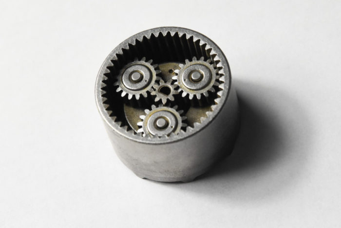
Planetary gears sets have 4 major components: sun, planet(s), ring and the carrier or arm. The planets are assembled onto the arm. The planets mesh with the sun and the arm rotates around and on the same center line of the sun. The planets also mesh with the ring gear.
Generally, either the arm, ring or sun will be fixed in rotation so predicatable motion will occur. In rare cases, the input and output are linked together so that there is no relative motion between the sun, ring and planets. Automobile transmissions use multiple systems and sometimes the sun and the ring will turn to provide power to the arm.
Sizing the Gears
It is important to size each of the gears so that they fit properly. There are two simple formulas that will help you choose the right gears.
First off, all of the gears must have the same diametric pitch in order to mesh. Next, the following equation will relate the number of teeth on the sun, ring and planet. The variables could also represent the pitch circle of the gears, but most use the number of teeth to quickly evaluate if the meshing will work.
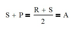
For example, if your sun gear needs 17.5 teeth from the calculation above, your system won’t work because teeth always need to be an integer. This is a little more difficult to see when using the pitch circle of the gear.
Calculating the Number of Planets
One of the main reasons to use planetary gear systems is to increase total torque. Every planet in the system adds a new path for force to flow. So where you may be limited by tooth strength, adding planets will allow you transmit the torque through multiple teeth. Genius!
Another benefit of having at least 2 planets is that it will balance the radial forces (force pushing the gears apart) on the shafts leading to smaller shaft designs.
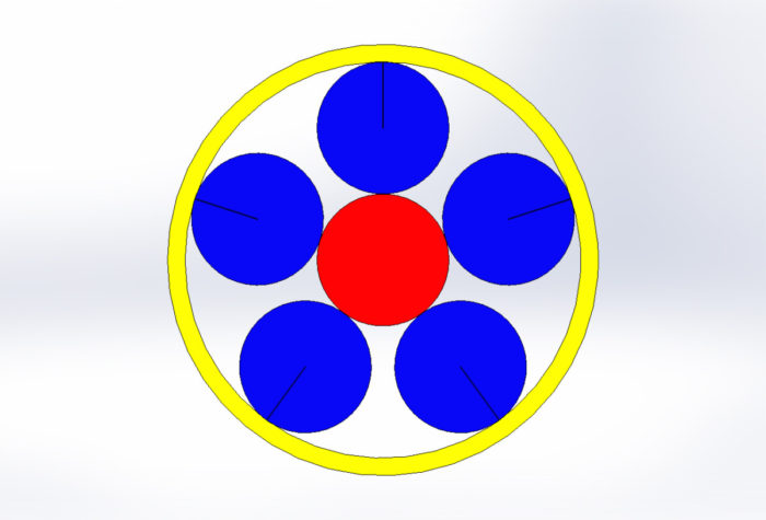
The number of planets for an system is limited first by the space available for the planets to occupy. A system with a small sun and large ring will have less planets even though there is more space available than a system where the ring is only 50% larger than the sun.
The other limiting factor is the teeth meshing properly. This can be determined by the following equation.

planetary gears
The result of this equation must be an integer for proper meshing.
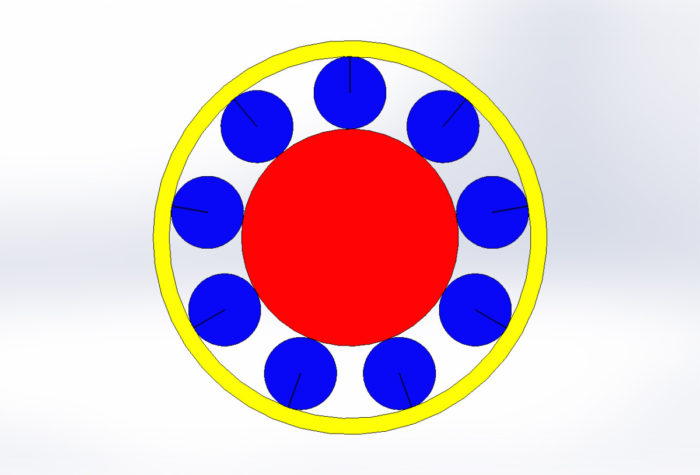
The top example has an R – S of 30 where there could be 1, 2, 3, 5, 6, etc. planets We find out that the spacial constraint is 5 planets.
Similarly, the second example has a R – S value of 18 leading to 1, 2, 3, 6, 9 and 18 planets. This design can support 9 planets.
Calculating Motion of the Components
Generally speaking, we care about the motion of the carrier arm, the sun and the ring. Usually, one of those will be fixed, but there are many times that they may all be moving. Automatic car transmissions are a great example of this. The following equation relates all the components together.

Where S is the number of teeth on the Sun, R is the teeth on the Ring, ωr is the speed of the ring (usually rpm), ωa is the speed of the arm and ωs is the speed of the sun.
For example if we take the second example up there with R = 45, S = 27, P = 9 we can find out the relationships:
| Fixed | Input (1 rev) | Output (rev) |
| Ring | Sun | Arm 0.38 |
| Ring | Arm | Sun 2.67 |
| Sun | Arm | Ring 1.60 |
| Sun | Ring | Arm 0.62 |
| Arm | Ring | Sun -1.66 |
| Arm | Sun | Ring -0.60 |
Multiple Planetary Sets

You can also apply this in steps to get multiple reductions. For example consider the reduction a drill I recently disassembled. (R – 45, S – 9, P – 18) There are two stages in the reduction, where the arm on the first section drives the sun on the next section.

In the drill, the ring is held fixed except when the torque is greater than the desired setting. At this point, the ring will slip and no output motion will occur.
To calculate the output speed, we will need to use the equations below. It is the universal equation used twice and the speed of the first section’s arm is set equal to the second section’s sun

Since the gears have the same number of teeth in the first and second sections, we will have the same reduction in each section which is 1 : 1/6 (input/output) or 6 input revolutions to 1 output revolution. When both sections are combined the ratio multiplies to 1 : 1 / 36 or 36 : 1. Gearbox ratios are commonly referred to as input to output revolutions.
Calculating Torque
This 36:1 ratio gives a tremendous mechanical advantage because it allows the use of a small and fast electric motor to have tremendous torque on the output.
The ratio of input to output (N) is 36:1 for the drill. The relationship of speed and torque can be calculated using the following equations:

As in normal gear equations, as speed decreases, the torque increases. With normal spur gears, you can only transmit torque through one set of meshing teeth. However, you can multiply the available torque by the number of planets in the system. This is provided that the gears and other components involved have a high level of precision.
Conclusion
Planetary gear systems can be intimidating, especially if there are multiple sets. Break them down into smaller sets and tackle them one at a time. Count all the gear teeth and then run the equations to confirm that you counted correctly. These systems can be simplified greatly with just a little analysis.
For Further Study
If you want know more about gear system designs, read the article below. To calculate the torque that a gear can transmit, the section on gear tooth forces begins about half way through.
How to Use Gears – What You Really Need to Know
How to Achieve High Ratio Planetary Gearboxs


