

In college we learned all about torsion and the polar moment of inertia. However, school can be over simplified at times. A colleague and I learned this the hard way.
We were designing a 20 foot (6m) lattice structure with 4 angle irons running lengthwise. About every 24″ we ran a cross member making a rectangle to hold the section together. We also added in diagonal angles to carry the moment load on the lattice.
I suggested that we do a torsional calculation like we learned in school to figure out if it was strong enough. We used the section properties in Solidworks and it boasted a high Polar Moment of Inertia and low torsional stress. We continued with our design.
A few weeks later, we starting running Finite Element Analysis on the design and the structure lit up like a Christmas tree! At first we thought it was an error in the loading, but we quickly realized the problem. The torsional deflection was excessively high.
We went back and calculated our torsional deflection again and found no issues. Now, it was time to summon to “old guy” to come help us out. It didn’t take but 2 minutes for Marvin to set us straight; the traditional formulas for torsion just don’t work on open sections.
The Polar Moment of Inertia is a member’s ability to resist twisting from torsional loads. Resistance to torsion is based entirely on the shape of the section and not the material properties. The Polar Moment of Inertia can be used to calculate shear stress and torsional deflection.
Traditional Polar Moment of Inertia Formulas
The traditional formulas for the polar moment of inertia work only for closed or continuous sections. These are sections like round bars and tubes. If a section has a few holes or a short slot in it, it is still considered closed. However, if the slot is substantial in length, you now need to consider this as an open section. Knowing if the slot is substantial depends on the beam shape and length, slot length and torque applied.
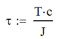
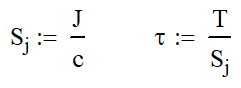
There are two main equations where the polar moment of inertia is used. The following equation will calculate the shear stress in a section. τ is the shear stress, T is the torque applied, c is the distance from the centroid to the outer fiber and J is the polar moment of inertia.
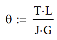
The other equation is for finding the torsional deflection. θ is the angle of deflection in radians, L is the length of the member and G is the shear modulus of elasticity of the material. G can be looked up in reference tables or calculated from Young’s modulus and Poisson’s Ratio
Calculating Polar Moment of Inertia
If you have 3D CAD modeling software, you can easily “calculate”, er…find the polar moment of inertia. If you are using Solidworks, first select the end of the section. Then go to Tools->Evaluate->Section Properties.
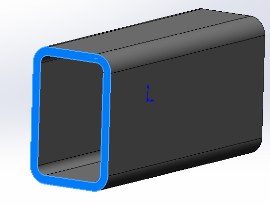
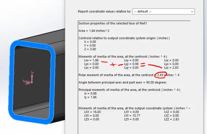
This will bring up a lot of information. Don’t get overwhelmed because we don’t need most of it. The circled number is the polar moment of inertia at the centroid. In the section above that, you will get 9 numbers and 6 of them will be zero. The ones that aren’t are the area and polar moment of inertia.
One thing to note is that the two are moment of inertia will add together to give you the polar moment of inertia. This means that it will always be the largest number there, which prevents confusion when your coordinates may be in a different orientation.
Every major 3D CAD software has a method to look up the section properties. Take a few minutes to do a web search. If you don’t have 3D CAD, why not? I guess we will have to do this the old fashioned way. No not calculus…look it up in tables.
The table below has the polar moment of inertia for common shapes. Here are the Polar Moment of Inertia on common shapes. I have add a column for the “Torsional” Section Modulus, Sj, which is a term that I have come up with. It is similar to the section modulus for bending, but it is used with torsion. In many cases, it will speed the calculation process along, but in others it will only make it more cumbersome.
I just want to reinforce that I have not seen this method formally taught, and I made up Sj. If you have a better denotation, please share it with me. My contact information is in the footer.
Torsional sections with thin walls are susceptible to buckling and denting. Soda cans are strong in torsion, but dents cause stress concentrations and buckling with shrink the enclosed. Both reduce the torsional capacity of the section.
| Shape | Image | Polar Moment of Inertia | Torsional Section Modulus | Stress Formula |
|---|---|---|---|---|
| Round Bar | 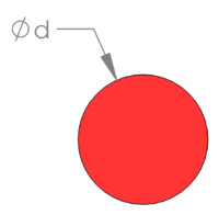 | 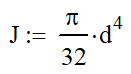 | 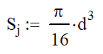 | 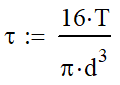 |
| Round Tube | 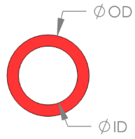 | 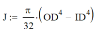 | 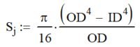 | 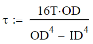 |
| Square | 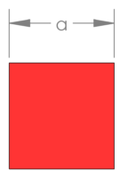 | 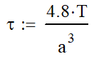 |
||
| Rectangle | 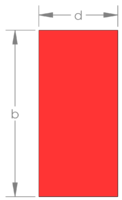 | 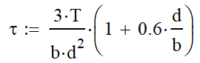 |
||
| Rectangular Tube | 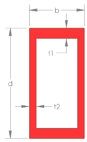 | 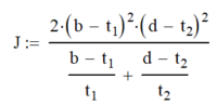 | 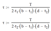 |
|
| Hollow Blob | 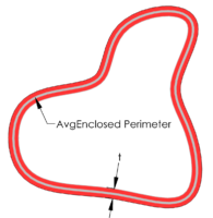 | 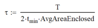 |
When Not To Use the Polar Moment of Inertia Formulas
The situation above taught me a lot about torsion and how unique it can be. In the first weeks of my strength of materials class, we learned that the maximum shear stress occurs about 45° from the maximum axial stress. This gives great insight how to visually see torsional stresses in beams.
If I think about an axial stress wrapping around the outside of my section at a 45° like the candy cane below, I can see where there is a clear path and where there isn’t. These are what we call closed and open sections, respectively,
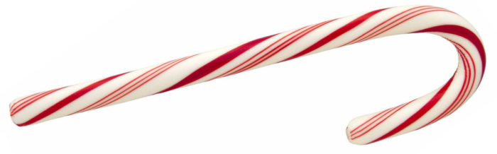
The lattice boom is a clear example of an open section. Using the candy cane method, the flow of stress quickly falls apart. There is no clear and direct path for the stress to flow. Open sections need special care and there aren’t many clear cut formulas .
Traditional Stress-strain calculations for torsion only work for closed or continuous sections. Open sections, like a lattice structure, need to be analyzed by torsional resistance. Omer Blodgett’s Design of Weldments gives a great method to calculate torsional resistance.
Wherever possible, try to use a closed section like a bar, or tube. Even if you have an open section in torsion, there are ways to improve the torsional rigidity in a member. The following article details ways to minimize torsion in common applications.
In order to design a better section for torsional deflection consider using closed sections like bars or tubes; avoid plates and structural shapes. You can also box in open sections, thicken walls and apply bracing.
At a former job, we frequently encountered this following issues when a torsional load was applied to a round tube with a hole in it. As we made the hole larger, this became more of an issue. We solved it by making the hole a diamond with rounded corners. The forced the candy cane stress to pass easier where it could and reduced the maximum stress.
Featured Image Courtesy of Paul VanDerWerf