

There are many times in my design career that I needed to translate an object without rotating. Lifting an object on a table is a great example of this. At an airport we may see a baggage loader using a scissor lift to load and unload your personal items. In most cases, we want to maintain level with the ground, but often we just need to keep the same angle. I once designed a holder for a seam welding robot that needed to keep the tip at a specific angle relative to the part. It was not horizontal.
There are five main ways to move items without rotation. They are:
- Parallel Links
- Chain and Sprocket Leveling
- Scissor Lifts
- Hydraulic Leveling
- Electronic Leveling
All of these have their strengths and weaknesses and we will discuss them. Let’s explore each one more.
Parallel Links
Parallel linkage is probably the most recognizable method of keeping level. Two equal length parallel links are hinged to fixed pivot points. The line drawn between the two pivot points is the line we will remain parallel with as we rotate the links. Please note that the links do not have to be straight. They are two force members (like a rope in tension) so if they are not straight, you will have additional moments to calculate. It is also self-evident that you cannot get continuous rotation with this system because the links will interfere with each other.
There are two main things to consider about designing a system of parallel links. They are load magnitude and load placement.
The placement of the load has no effect on how hard it is (for the cylinder) to lift up the load. It seems backwards, but the cylinder is only responsible for lifting the magnitude of the load. The placement of the load is managed by altering the force in the links. This is why you often see small cylinders lifting large loads. Let’s dive deeper into the math.

So, I’m going to prove to you that the placement of the load does effect something, but it doesn’t affect our cylinder load. For my first case, I’m going to put one hundred pounds right over the pin, and calculate the tension in the member left link. Doing the statics you need to sum the forces at the pin where the load is applied. The moment is the load (100 lb) times its moment arm (0 in) divided by the distance between the bars (11.26 in). Anything multiplied by zero is still zero, so there’s no force in that link. It’s kind of along for the ride and it’s just making sure that the bar maintains level.
I will now move my load out 20 inches and recalculate. I’ve now got a moment of 100 pounds times 20 inches or 2,000 in-lb. If I divide that by 11.26 in, my force will be 178 lb. So, I’ve increased the link load significantly by moving it out 20 inches. The tension member is very easy to calculate, but the compression member is a little more complicated because of the cylinder. The statics on the compression link is a little out of the subject so I won’t cover it in this article. It isn’t too difficult to calculate anyway.
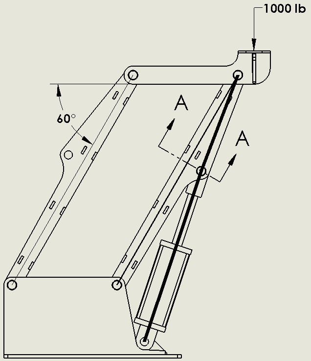
Now let’s move onto the calculation of the cylinder force. It is largely a function of what the moment is at Section A-A. This moment is equal to the distance (12.56 in) times the load (100 lb) times the angle between the two (60°) which equals 628 in-lb. Because of the pivot point at the end of the link, there will never be an increase if the load doesn’t increase. To say it another way, the shear load in the top member is always 100 lb, but the moment load changes. We are only concerned with the shear load in this calculation. (Please note that the moment at A-A will change as the angle changes, so be careful). With linkage, you can get away with a relatively small cylinder to lift heavy loads because of this principle.
Load placement is critical for designing a system of parallel links. You can actually double the loads in a link if you are not careful. In the example above, I may have a load that centers on the pin and through its travels, the load may actually slide to the left or right. If we were using this to load baggage onto an airplane, we would have loads that shifted from roughly the center to the edge of the structure. I mention this because we always want to have the cylinder interface with the compression link and we always want the compression link to stay in compression.
The reason that it matters is simple statics. Looking at Figure 2, the stress flow is clear. Our cylinder is in compression (if I remove it, the structure will fall to the right). As long as the link is in compression, the stress will flow nicely as shown with the thick line. However, not all of this load will flow through the cylinder (especially as the angle changes) and a small amount will be directed to the link. The point is that we will have a smooth stress flow throughout the link and cylinder.
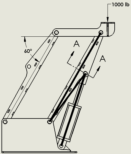
If I move the load further left of the left link, I will change the direction of force in the right link. The link with the cylinder is now in tension. (Note that if the load is between the links, both will be in compression). Now the cylinder is still in compression as it tries to hold the load up. If we look at the modified stress flow in Figure 3, we see that the primary stress flow is between the two pivoting pins and it is in tension. However, the compressive load of the cylinder needs somewhere to go. It wants to go up to the top pivot, but there are no forces to balance with. It then needs to make a U-turn (it’s quite awful) and flow back to the lower pivot. This stress from the lower pivot to the cylinder mount is a tensile stress and will add to the tensile stress of the link. The result of the link being in tension is an amplification in stress. Also note that stresses don’t like making U-turns. By definition, it is a large stress concentration and will have you pulling out your hair in FEA (yup, been there). As a rule of thumb, always try to have your loads biased so that the member of the cylinder is in compression so that your links can be small and effective. In the rare case where I couldn’t prevent the reversing of loads, I was usually able to minimize the effects by limiting the offset distance and the magnitude of the load.
Parallel links are powerful tools and are used in many different types of machines. The benefits of using small cylinders to lift loads are self-evident and allow the lifting of heavy objects at longer distances.
Chain and Sprocket Leveling
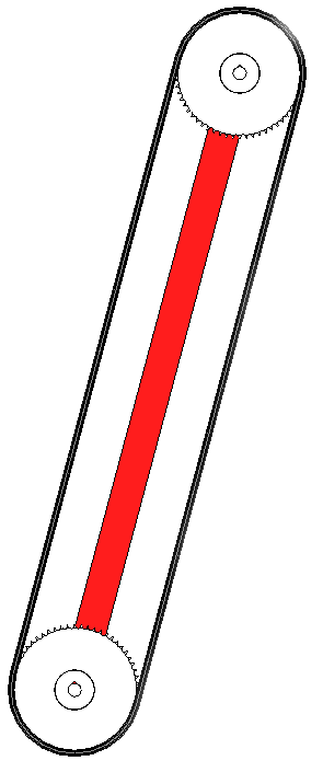
One of the limitations of parallel links is that you cannot do continuous motion. In fact, the practical limits of a parallel linkage system are usually below 125°. Of course, there are always exceptions. Now if articulation is a limitation that you need to have eliminated, going with the chain and sprocket form of leveling is a better idea. A chain and sprocket leveling system or ‘chain leveling’ works by having a bar or link of a fixed length and mount a sprocket on each end. The sprockets must have the same number of teeth to work properly. A chain then goes around the two sprockets. The sprocket that is mounted at the pivot is usually fixed. So, as you rotate the link around, the chain winds on one sprocket and unwinds on the same amount on the other sprocket. The result is the free end sprocket staying in the same rotational position throughout its motion. Also, if you setup the geometry so that the components don’t interfere, you can go 360 degrees around this if you need to and you could do it continuously – not just single rotation!
As you can imagine, backlash and chain slack is important so having a method to tension the chain is needed. This can be done by adding a chain tensioner or even making the link adjustable.
Chain leveling is also a great choice if you need to electrically insulate the ends. By changing from chain (and link) to a non-conductive material it is possible to have each end of the device at different electrical potentials. When you do that, you lose the ability for continuous rotation.
When calculating the loads on a chain and sprocket system, we run into a few issues calculating the loads. We immediately notice that the chain will act as a couple (two parallel forces in the opposite direction but equal in magnitude and separated by a perpendicular distance [obviously]). However, chain doesn’t handle compressive loads and will slack under any compressive load. Once the chain goes slack, we now have to create the couple in the tension side of the chain and the link.
Let’s work a small example. A chain leveling system will have a sprocket 20 inches in diameter and a preload of 1000 lb on the chain. A moment of 30,000 in lb is applied and then removed.
To solve this we must load the system in two steps. Step 1 is to unload the chain on one side until the applied moment is equal to the chain pretension. At this point the tension side will have the same load as the pretension value, but the other side will be completely slack. It is important to note that there will be no increase in load on the tension side at this time. We are just unloading the slack side. In our example this is a moment of (20 in)*(1000 lb) = 20,000 in lb.
In Step 2, we have to load the remaining 10,000 in-lb by using the center link as the distance for our couple which actuates at half the sprocket diameter. So 10,000 in-lb / (20 in / 2) = 1,000 lb. When we add this to the preload, we find that the tension in the chain will increase from 1,000 lb to 2,000 lb as the moment is added.
 In practice, we want to minimize the load induced in the Step 2 calculation by having a good amount of preload in the chain. This will prevent fatigue from being a failure mode.
So one neat thing with chain leveling is that you can route the chain however you want to, as long as the sprockets on the ends are the same size. You can route the chain over as many other sprockets as you need to. You can even have the two chains running right next to each other! I’ve seen cases where a large sprocket is needed, but it will not fit into the tube. The solution was to have the chain run across plastic wear pads and ‘dog bone’ into a smaller tube.
One benefit of chain leveling over parallel links is that we can rotate the bottom sprocket and make the top one rotate as well. This is useful for periodic cleaning; when the bottom sprocket is rotated, a once horizontal surface at the top sprocket is now vertical and debris or collected water can easily be removed.
There are two other drawbacks of chain leveling systems. The first is there is a practical limit to the moment that can be handled. This is limited by the size of the sprocket and the size of the chain. The other limitation is the same as parallel linkage. The translation is at a fixed radius and the motion is limited to polar coordinates. This means that there is no linear motion, just angular.
Scissor Lifts
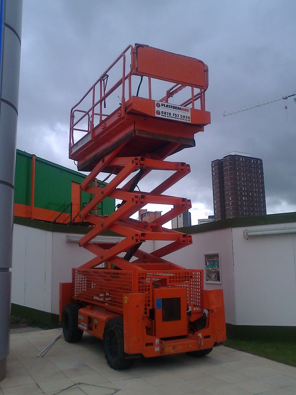
If you need linear motion in one direction, scissor lifts are your “go to.” The structure is named after the well known cutting tool and they will cut or at least smash your hand if you get too close. They are the predominant method of lifting materials in a linear fashion to heights far exceeding the collapsed height.
Scissor lifts seem pretty obvious as to how they work, but they are more complicated then they appear. First of all, calculating the forces on the system is extremely complicated. In fact, some scissor lifts are statically indeterminate based on how the cylinders attach. As an approach, each link will need to have a separate Free Body Diagram and many sets of equations are needed to find all the resultant forces.
A scissor link will have five main components: links, a base with sliding surface, a top with sliding surface, sliders and a cylinder. Two cylinder locations are shown but more are possible. The angled one is the most popular because it allows the cylinder to be in compression thus creating more force. 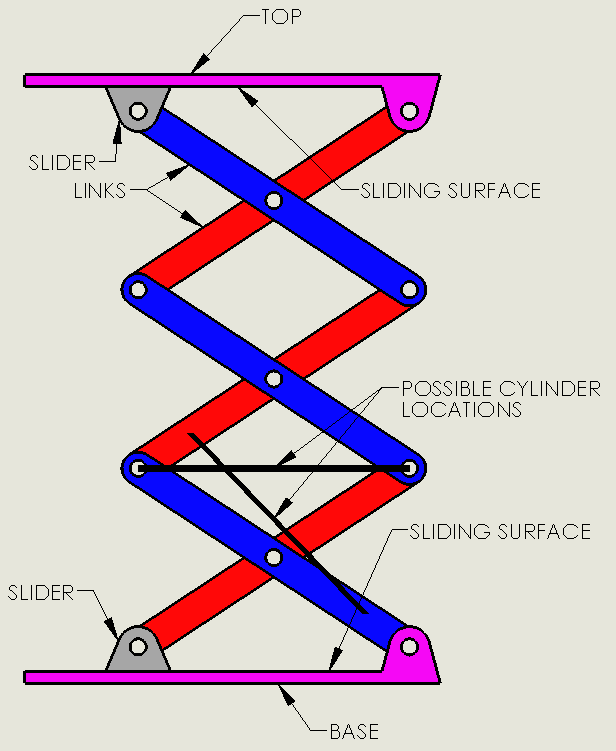
Some things to consider in a scissor design is how the top member is loaded. If the sliders ever get into tension, there will not only be slack in the system, but you will need to have a way to retain the sliders to the top and base components. One way to minimize or eliminate that is to bias the loads so that they are closer to the slider reaction point than the pivot points. You will definitely want a way for the slider to remain connected to the top or base even if it is only able to take incidental upward loads.
Another thing to watch for is chatter. Chatter will often come from the sliding surface being too far from where the slider pivots. Minimizing the distance or maximizing the slider length can help. Often times, the use of cam rollers for the slider is a great design.
One great thing about scissor lifts is how readily available they are! You can easily find versions powered by electric, pneumatic, spring and hydraulic actuation.
Hydraulic Leveling
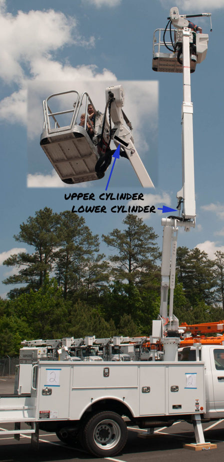 Hydraulic leveling is the most complicated mechanical method of keeping a surface level because there are many components that need to be factored in. The traditional use is for platform leveling on a man lift. At the platform, there would be an upper hydraulic cylinder between the platform and the boom. This cylinder is driven by a similar lower cylinder between the boom and the riser or knuckle. It is important to note that the lower cylinder does not raise and lower the boom, it is there to tell the upper cylinder what to do.
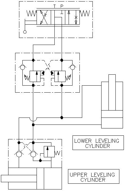
How it works: Looking at the schematic below, we can see that there are five main components: The upper and lower cylinder, a load holding valve on the upper cylinder, a dual counterbalance valve and a directional control valve. The directional control valve and dual counterbalance valve are for retiming, so we will ignore them until later in the article.
We will illustrate how the system works by going through a cycle. We will start by having a boom in the lowered position so that the lower cylinder is retracted and the upper cylinder is extended. When the boom is raised, it will force the lower cylinder to extend. Oil in the rod section will be forced to leave and travel into the upper cylinder where it will build up pressure and pilot open the counterbalance valve and enter in the rod section there. Oil from the bore section of the upper cylinder will be forced out and travel to the lower section. When we lower the boom, the opposite happens.
 To design good hydraulic leveling, you will want to consider six factors:
- Cylinder Size: The first thing that you will want to do when designing hydraulic leveling is select cylinders with the same geometry. The bore and rod size and the stroke length must be equal. If there is any difference, you are not going to get good results.
- Extra Stroke: It is recommended that you allow for at least ¼” of extra stroke on each end lower cylinder. You don’t want to get into a situation where the boom lift cylinder is not quite all the way extended, but the lower cylinder is extended already. As you can imagine, the boom lift cylinder is much more powerful and it is going to pull the lower cylinder apart. Very bad things will happen. You also want extra stroke so that variations in fabrication don’t stack up and cause problems.
- Load Holding: Hoses occasionally break, so you also want to add on load holding right on the upper cylinder to prevent any unintended motion of the platform. Counterbalance valves with 3:1 or 4.5:1 ratio should do well in this application. Be sure to set them at least 15% higher than the system pressure.
- Limit Pressure and Fluid Velocity: In order to keep these cylinders timed we need to limit the pressure and fluid velocity. First off, you are going to want to look at the velocity of oil that’s exiting the cylinders and keep it to a velocity of less than 10 feet per second. This would be the same as you would have for a standard hydraulic return line. The reason for this is that you don’t want to have large pressure drops just to move the fluid back and forth between the cylinders. You want the fluid to do the work of maintaining level and not just trying to get out of a counterbalance fast enough. Increase your hose size to remedy this. Keeping your working pressures low is also important. You will want to be working with pressures about 2/3 of the system pressure. For a 3000 psi system, we will want to have our cylinder operate at 2000 psi. The reason for this is we don’t want sudden pressure spikes causing the counterbalance valves to open and level to change unintentionally. As a result, you will need to increase the cylinder bore and stroke length on both cylinders.
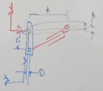
- Account for Deflection: This is probably the most overlooked criteria because it is not obvious. In an ideal world, designing the cylinder geometry exactly the same on both ends will work perfectly. Making geometry the same would require that the dimensions (A, B, C, and D) in the picture here are the same for both the upper and lower cylinders. Keep in mind that the rotation of these components can be changed. However, this is the real world and booms will deflect. When the boom is loaded in a horizontal position it may deflect 5° but when I have the boom near vertical, it may only deflect 0.5°. If we don’t account for that, the platform will not track correctly and be out of level. To account for this, the cylinder geometry must cause the platform to rotate 4.5° more than the boom rotates. This causes the cylinder geometry to be slightly different on each end.
- Manual adjustment: Hydraulic leveling isn’t perfect and from time to time, you will need to adjust the platform level. In the schematic above, we will need to add a directional control valve for two reasons. The first is obvious; to occasionally adjust the platform level. Second, we need a way to prime the cylinders and hoses. Air is not a friend in any hydraulic system, so getting oil in and air out is important. Closed systems like this one are difficult to get the air out so I recommend cycling the platform fully when the boom is up and down twice.
Direct use of a direction control valve with closed center work ports presents two problems. First, if there is a pressure spike, flow back to the tank is blocked so the system will need to absorb the excess pressure. The second reason is that while the schematic shows the ports being blocked, in reality the valve does have small amounts of leakage. This is due to the valve spool having a small amount of clearance in the hole that was bored. While this amount of fluid is small, it is usually measured in drops per minute. Leaving a unit setup overnight might yield a dramatic change in platform angle.
Placing a dual counterbalance valve in between the directional control valve and cylinder circuit solves both of these problems. It will make a no-leak seal on the cylinders but also allows for relief from pressure spikes as well as thermal induced pressures. These counterbalance valves are purely for load holding so using a higher ratio valve is appropriate. I recommend a 10:1 valve set at 15% higher than the system pressure.
Hydraulic Leveling
Type 2
There is another type of hydraulic leveling where a level switch activates a directional control valve when the platform is more than a few degrees out of level. This type of leveling is simple, but very jerky and has a ratcheting effect. I mention it only to round out the picture because this type of control has been replaced with electronic controls.
Electronic Controls
Electronic control systems for leveling systems are where the industry is going. An electronic control system will monitor an analog sensor or encoder based level indicator and make adjustments as needed. Using a PID or equivalent control system, hydraulic cylinders are actuated by proportional directional control valves. Using proportional valves allows for near seamless leveling control and includes the possibility for controlled acceleration and deceleration. Electronic control systems can also control leveling in two directions.
Conclusion
Lifting objects is an essential part of engineering. Keeping them level throughout the lift is a welcomed challenge but can be stressful. After reading this article you should be able to select several practical methods of lifting without rotating. You should also be able to take initial steps to designing each type of system.
I am not an engineer but have an idea I think these parallel links might work for. In the garage have 6′ cabinets and 12′ ceilings.
If I could make a shelf that could pivot from the floor to above the cabinets to say store a snowblower.
You mention “It is also self-evident that you cannot get continuous rotation with this system because the links will interfere with each other.”
What if 1 parallel bar say the back was inside and had a little cutout in the back of the shelf and the front parallel bar was on the outside?
Jake, it hard to say from your description. Do you have a sketch you could send to me? My contact info is at the bottom of the webpage.
I am in a pumpkin carving contest (my family & we each have remote partners doing a separate design). My dad is an engineer & inventor & he is now my competitor! I have a design in mind & no idea how to pull it off! Any chance you can help? I am carving a witch out of a smaller pumpkin (5-6” round hopefully) and a cauldron out of a much bigger pumpkin. I want the witch head to ROTATE AND RAISE UP out of the cauldron, which will be equipped with dry ice. The top of the cauldron can double as the witch’s hat if possible. I have a cornhole board that has table legs standing about 3.5’ high (which my dad built & painted, one board is a day scene of a “scary house” & the other board is a night scene of the “haunted house”). I thought about using this table as the hole in it could be perfect for placing the cauldron with any mechanics through the hole hiding under the table. I can make this happen manually or electrically… do you have ANY suggestions on how to get this corkscrew effect? I’ve thought of stand mixer, upside down, ice cream machine & even thought about a drill. But that’s for the rotation. How do I also raise the head up while rotating & not too fast?? I know this is probably the most random message you’ve ever received! But if you have any ideas I would be so grateful!
Thank you!
Janna Abele
jannaabele@att.net
Janna,
Cool project. With your deadline, I would investigate https://www.frightprops.com/ or building something out of Legos. Thanks for the inquiry!