As engineers, we want accurate model for finite element analysis, but with more accuracy comes longer run time and difficulties meshing. The method shown below is a way to gain maintain accuracy while reducing run time.
To get an accurate Finite Element Analysis results for a weldment with shorter run time follow these steps:
- Model each weldment as one part
- Add in welds as chamfers
- Make cuts where needed
- Apply mesh controls on welds
Mesh Singularity – Before we get too deep into the
weeds here, I want to point out the mesh singularity may or may not be an issue
here depending on the model’s particular geometry. Since there are a sharp corners in the model
there is the possibility of mesh singularity and divergence in results. Divergence is when the mesh is refined more
and more, but the stress at a particular physical location usually increases
dramatically as the mesh is finer. This
makes interpreting the actual stress very hard.
Mesh Singularity and Divergence require a whole article of their own and
are out of the scope of this one.
Welds – The main part of what makes a weldment is welds. Naturally, the stress will flow different through a weld than if we just had the parent materials present. Therefore, we need to model the welds and their proper sizes to get trustworthy results. In a previous role, a colleague did not model welds and modeled a doubler plate as part of the primary structure. A plate was attached to the doubler and a load was applied that pulled the doubler away from the primary structure. Since no care was given to the weld or doubler, the section was modeled twice as thick and FEA showed no high stresses. The welds cracked quickly in an endurance test. The point of the story is that welds matter in our FEA models so we should spend the extra time here to get the model right.
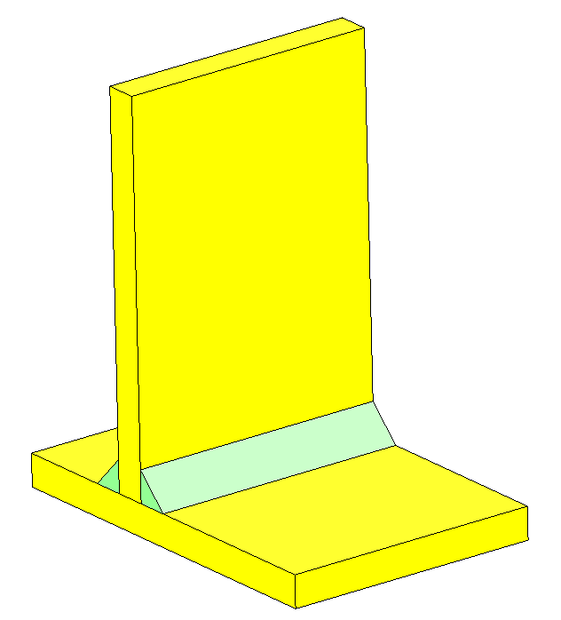
Most welds factor into 2 categories; bevel and fillet. (By the way, I have no idea why a fillet weld looks like a chamfer; should we not call them chamfer welds?) Fortunately, a bevel weld does not need any additional modeling done. The fillet weld is more difficult because it requires additional material and then special consideration for how the parent materials behave. Looking at the figure here, the yellow plates are joined by two fillet welds. These welds need to be modeled and then the contact between the two yellow plates needs to be addressed. One method is to use a no penetration contact and the other is to use a distance mate to separate them slightly. Both of these are ideas that don’t move us toward our goal, so we won’t pursue them further. Let’s get on to the plan.
Model Each Weldment as One Part
This is where the time savings comes from. The main benefit of modeling a weldment as a part comes with the meshing headaches you will avoid. When meshing lots of parts in Solidworks Simulation, the parts that touch need to have all the same mating nodes. This can be very difficult for the software to do. One trick for this is Solidworks sorts the parts alphabetically and meshes in that order. You can reorganize the meshing order by renaming parts A_, B_, etc. so that the most complex parts are meshed first and get to set mesh parameters for the simpler components. This has saved me many headaches over the years.
The other way that modeling a weldment as one part helps to reduce FEA run time is it allows you to remove any contact sets from the analysis. This removes a lot of run time from the solver process. In the figure above, most designers would add a no-penetration contact between the yellow plates, but this adds so much time to the analysis. See the data in the tables below for run times by model type.
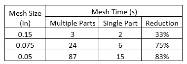
We can see here that the main benefits with switching to a one-piece weldment is reduced run time by removing contacts and less headaches from meshing failures.
Now I know that you are all thinking, “It is going to take more time to model this.” And you would be right; well, kind of right. You see with the two benefits mentioned above the time savings in FEA are well worth the time setting up the model. However, I would challenge you to go one step further and model it as one piece as you are designing it. This will save even more time! If you model as one piece from the start, all you need to do is make a few tweaks for FEA. You can also send it to a drafter and he or she can break down the model into piece parts. This has proven effective because the drafter will not only have a great template to go by, but he or she will know where all the welds go and what size they need to be. This one step can be a tremendous time saver for the whole design process!
Add in Welds as Chamfers
So one of the awesome benefits of modeling a one-piece weldment is that you can easily add welds to the model via the chamfer option. This allows Solidworks to process very complicated geometry with very little effort. I usually choose a weld with equal legs rather than one with a leg length and an angle. I do this so that even if the welded components don’t meet at right angles, the weld will be modeled correctly. I also label the chamfer with the size so that I can easily see what size welds I need (i.e. 25-chamfer). This way I can add or remove welds from different features as they change sizes.
Make cuts where needed
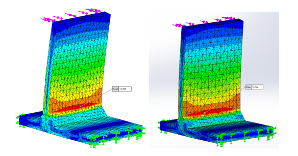
In the figures below, we can see that the stress flow is different when we go from the no penetration multi-part model to the single part. Our run time has been reduced dramatically, but our accuracy has gone down a lot. The model is loaded with lateral 100 lb. load and the two ends are fixed. When calculated by hand, the stress should be 13,221 psi in the high stressed area. The left figure is the multi-part model where the stress moves around the no penetration contact. The right figure shows the stress flowing through the center where the two plates intersect. Obviously, this is not a proper stress flow path.
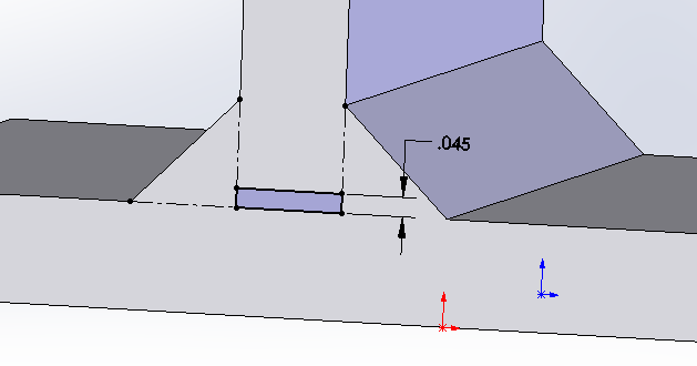
To remedy this problem, we need to make a cut in between the two plates. There are three ways to do this: make the cut go up, down or split the difference. The choice you make will depend on your situation. Going up might be more accurate in one case, but less accurate in another. One thing to mention is that the location of the cut will affect the results, but it will have very little impact on the run time. The cut below is shown going up with a gap of 0.45” and is as wide as the vertical plate. The 0.045” gap is a gap that Solidworks seems to like when meshing. There are situations where you may need to go up to 0.0625” if meshing fails.

The table here shows the results for the multi-part, single part with welds and then adding the cut up or down. As you can see, the results are very accurate for the coarser mesh of 0.15” but get worse as the mesh is refined. This is the problem of singularity I warned against earlier. To minimize the error, I recommend getting three elements (4 nodes) on the face of a weld. For a right-angle fillet weld, this is as simple as mesh size = weld leg / 2.13. In our case the ¼” weld gives a mesh size of 0.117”. This is a good rule of thumb and it is not always exact. You will need to inspect the critical welds for three elements along the face. Going less than that is just too coarse of a mesh and small gives untrustworthy results. For example, the figure below (single part with the cut going up) has 6 nodes on the face of the weld.

A word on accuracy – As engineers, we need to make assumptions and judgement calls all the time. This is one of those times. In my first FEA class, the instructor opened up with the statement, “All FEA is wrong.” He is right. You may have noticed that I went and did a simple hand calculation to get a reference for what the magnitude should be of the stress. I highly recommend that when you see FEA results you don’t like, do a hand calculation to see if your design is sufficient. Many times, simple calculations like this can save you a tremendous amount of time and frustration.
In this problem, I used my formula to get a mesh size for the weld which was 0.117”. The results from the multi-part run were 5.7% higher than the calculated stress. The cutting down model gave us the best results of 13,654 psi which is off by 3.3%. To be honest, I am generally happy with FEA results that are 5% to 7% off of the calculated (or measured) valve. I get that good, warm fuzzy feeling when the FEA results are also higher than the calculated value, this means that when I design for the stresses in FEA, the design should have inherently lower stresses. If your hand calculation stress ends up being higher than the FEA results, check your mesh at the weld. You can adjust this as necessary to get better results.

A doubler example – The fillet weld example is the primary complication experienced when changing from a multipart weldment to a single part weldment. The other complexity is the doubler plate. This one is a little simpler in the approach. Simply model in your doubler with an extra 1/16 inch in height and add the welds that secure it in place. You will then make a cut on the inside of the doubler that is 1/16” think in the shape of the doubler. This will give you the proper weld size and plate thickness.
If you doubler is designed to take loads normal to its surface, you may run into issues. If the load is compressive in nature and pushes the doubler into the primary structure, this cannot be modeled without the aid of multiple part weldments and no-penetration contacts. While this may be a tendency for some engineers, I would recommend against it. There is no guarantee that the plates used will be perfectly in contact with each other after welding, or even before welding. This would then require the doubler to deflect some amount before coming into contact with the primary structure. You are a better engineer than I am if you can predict this.
Instead, I recommend that you assume that the doubler takes all the load. If the doubler absolutely needs to utilize the primary structure, add plug welds near the load application point will make a huge improvement.
In our example we have a 2.5” OD tube welded to a doubler and that is welded to the primary material which is a round disc with the edge fixed. (In practice, this is poor practice because it puts the root of the weld in tension. Since you can’t inspect the root of the weld, we can’t see any cracks until they have propagated all the way through the weld. Some plug welds could remedy this issue.) As you would expect, the tensile loading on the tube pulls the doubler away from the primary material.
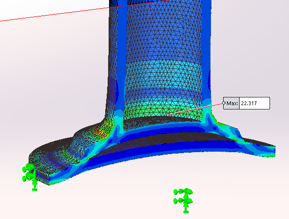
If we model this as a single part with no gaps, the two plates will act as one causing the stresses to be greatly reduced. This is what got my colleague in trouble.
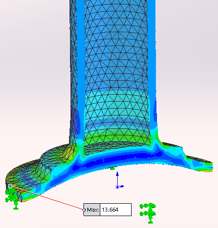
To remedy this, I added a 0.45” cut upward into the tube. I also thickened the doubler plate and added a cut that is 0.625” up into the plate. You can adjust the cut going into or out of the tube, but the cut should always go into the backside of the doubler plate.


Apply mesh controls on welds
To further reduce your run time, you can specify different mesh sizes in different areas. In this example, a global mesh of 0.10” took 17 seconds to run. If we change our global mesh to 0.25” and apply a mesh control to the weld surface of 0.10, our run time is reduced to 4 seconds without any degradation to the area of concern.


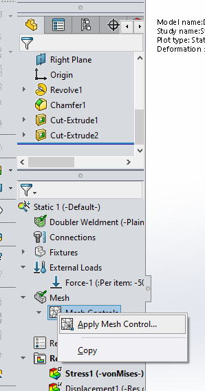
You can apply mesh controls by right clicking under Mesh and selecting Apply Mesh Control. Then select the faces that you want. I’ve selected the two faces of the welds and the small cutouts inside the part as well as the bottom of the tube. If you don’t like how quickly the mesh transitions from the smaller to larger size, you can decrease the a/b ratio. A value of 1.5 is the default, meaning that each element size can only be 1.5 times larger than the one next to it. This can be reduced so that the transition takes longer.

Check your model and look for deflection
As FEA engineers, we need to be thorough in our modeling and give it a check before performing FEA. The best method I’ve used it to look at sections of the model looking for the areas that need to be cut behind the weld.
Once you have your first run of FEA, be sure to check the deformation. Make sure that it is deforming according to what you would expect. Many times, this can be done by visual inspection.
The next step is to take sections of the model and inspect for high stresses on the internal surfaces of the model. The doubler example above is a great illustration of this.
Conclusion
Following this simple 4 step process can greatly reduce the run time and headaches of doing FEA on large weldments. This process also allows you to run larger models with multiple weldments without absorbing extra processing time. Just remember to:
- Model
each weldment as one part - Add
in welds as chamfers - Make
cuts where needed - Apply
mesh controls on welds
When applying your mesh control strive to have 3 elements (4 nodes) across the face of the weld for accurate, trustworthy results.

