In the midst of my first time specifying and installing a closed center hydraulic system with piston pump for a client, there arose 2 issues that I had not come across before, excessive heat generation and hydraulic shock. The heat issue was addressed in another article, but the solution used mitigated both issues.
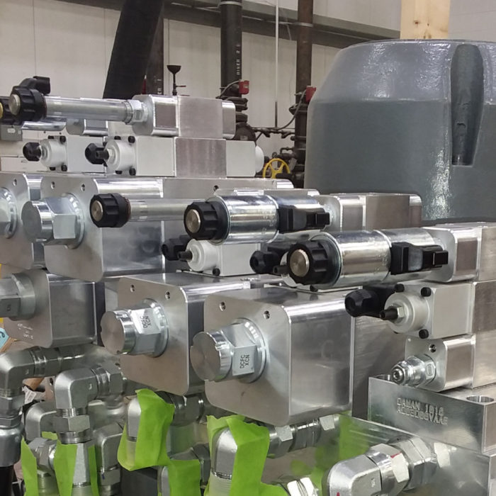
Hydraulic shock in closed center industrial systems is caused by the sudden reduction in pressure when valves open. This often happens when the pump is at standby pressure. To mitigate the shock, we can use load sense, tandem center valves, soft shift valves or reduce the standby pressure.
Let’s look at all of these. But first, let’s examine the problem a little more.
The Problem
The shock issue, sometimes called jolt, was clearly apparent when the pump went to the standby pressure of 3000 psi and then a valve was opened. The immediate release of pressure, shocked the system and created high forces on many of the machines components. Hoses jumping was prevalent.
Hydraulic shock is mainly an issue with industrial valve systems because of two reasons. They use closed center hydraulics and they lack load sense capabilities.
Industrial hydraulic systems are controlled with bar style manifold blocks. The manifold design requires the use of a closed center hydraulic system to operate multiple valves simultaneously.
Open Center Systems
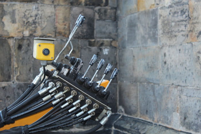
Open center hydraulic systems avoid the shock when a valve opens because there is little pressure to suddenly release. However, it will shock the system when a valve is closed suddenly at high pressure. In most hydraulic systems, this wouldn’t happen every time nor at full system pressure.
Closed Center Systems
Closed center mobile hydraulics tend to have a load sense capability where the pressure needed for the current function(s) is sent back to the compensator on the pump. The pump will output the required pressure plus a little extra. The extra is called the margin pressure and it typically is around 150 psi to 300 psi depending on the application.
The benefit of the load sense is that when no functions are activated, only the standby pressure is available. Therefore shock is minimized.
The Solutions
Load Sense
As mentioned, this is a common feature on mobile valves, but has yet to permeate the industrial valve market for various reasons. If this is a major concern on your project, consider using a mobile valve for your application.
Tandem Center Valves
A tandem center is a center arrangement where the Pressure and Tank lines are connected together. When multiple valves are used, the tank line is plumbed from one valve is connected to the pressure valve of another.
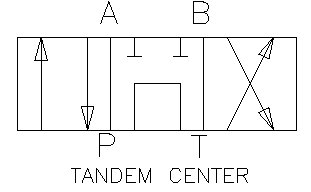
While this is an available option, I don’t recommend it for two reasons.
First, it will fundamentally change the system from closed center to open center. This means that all of the directional control valves will need to be placed in series. The series alignment of valves mean that certain valves will be given more priority in the system as each valve will alter the flow for every valve downstream.
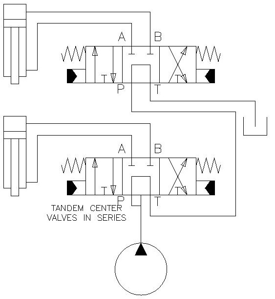
Second, plumbing multiple valves in series can result in lower, higher or no pressure if multiple valves are activated at the same time.
For more information on this issue, please read the following article.
Soft Shift Valves
Soft shift valves are gaining ground in the market place at an increasing rate. This valves have a middle position between two positions. The middle position usually has all the ports tied together with bleed notches so that when flow is reversed, there is not a sudden hard shift.
Having the bleed notch on the pressure line will gently let the standby pressure down when shifting the valve. Hydraulic shock will be reduced.

soft shift 2 position 4 way directional control valve
While soft shift is available, I have not seen it in a 3 position 4 way valve yet. This can be a non-starter for many control systems. Please let me know if it is available by sending an email to contact@mentoredengineer.com
Reduce Standby Pressure
In some hydraulic systems, you just don’t need the system pressure you designed for. As a good designer, you have calculated your pressures and flows for less than what is available. As a result, you may be able to reduce the standby pressure, but only minimally.
I say minimally, because there isn’t a drastic reduction in shock with this one. However, you know your machine better than I do, so maybe there is more energy savings here.
Going along these same lines, maybe we can reduce the standby pressure only at certain times. Let’s see how we can do that.
Adjustable Compensator Relief Valve
This option is the most expensive and most efficient. By using an electro-proportional relief valve (DO3 P to T relief valve for industrial applications), you can set the compensator pressure for exactly what you need for the current function. As the functions change, the compensator pressure changes.
Hydraulic shock is eliminated by having the compensator pressure reduced to 0 psi when the system is idle. No standby pressure!

This is the most expensive option because your PLC system is going to have to output an analog signal (usually 0 – 10VDC) to control the electro-proportional relief valve (also expensive). As a good designer, you will also want a pressure sensor to provide feedback on the system.
However, this system is fully customizable and can act similar to a load sensing mobile system. Through careful programming, you can tailor your pressure setting to what that function needs at any particular time.
This function would also allow you to gradually change pressures from function to function thus preventing hose jumping.
Be cautious, the programming can get very complicated. It may not seem to be a big deal now, but will cause headaches in years to come when you or others will need to service the machine.
Multiple Preset Compensator Relief Valve
This is a much simpler version of the adjustable compensator option above. In this scenario, we would have two or more compensator relief valves switched on or off by non-proportional solenoid valves.
In this system, there would be one relief valve (main relief below) tied directly to the compensator and other relief valves are separated from the pressure line by 2 position, 2 way, normally closed solenoid operated valve. The main valve must be set at the maximum desired pressure so that if all else fails, the system will have a direct path of pressure control. The other valves can be activated, one at a time, to control the pressure for certain pressures.

This system cost is also reduced from the adjustable relief valve option because it eliminates the needed analog control system and extra programming for the PLC.
Additionally, the system can be made to look quite neat as well. Having a multi-section DO3 manifold with the pressure port connected to the compensator will provide the foundation. Often, you can get the main relief valve already incorporated into the manifold which is a big bonus. You can then add solenoid valves on as the first row. On top of those valves you can add the individual relief valves.

If none of the sections are energized, the pump will create the maximum pressure which is set in the manifold relief valve. If one or more sections are activated, the pump will create pressure to the lowest set active pressure. In the schematic above, you can adjust the compensator pressure to 600 psi, 1200 psi, 2200 psi or 2750 psi depending on which sections are activated.
With this setup, you can customize the needed pressure while saving money, preventing heat generation and minimizing hydraulic shock.
Dump the Flow to Tank
This can be a subset of several other options. If your system idles for long periods of time, you can just have a 2 position, 2 way, normally closed solenoid valve dump the pressure to tank. This will destroke the pump and not create any heat or shock.
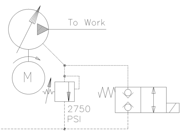
Which one did I choose?
To minimze heat generation, I put a two minute timer on when the system is in normal standby. There is also a 25 minute timer when the system is in the cutting mode.
I also added a 500 psi relief for a low pressure standby option. The system will standby at 500 psi but once a valve is opened, the system will also be triggered to go to the higher pressure. I accomplished this by adding a second compensator relief valve that is activated by a 2 position 3 way valve.
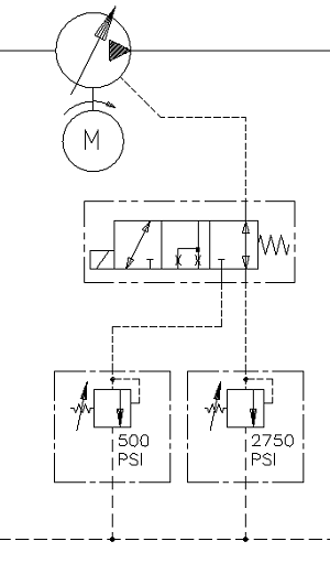
Reducing the standby pressure from 2750 psi to 500 psi also had added benfits of reducing the power needed by 82%. Sweet!
Conclusion
Closed center hydraulic systems are prone to excessive heat generation and hydraulic shock. There are several ways to minimize this effect. Adding a load sense system, soft shift valves and reducing the standby pressure are all methods of accomplishing this.

