

With the wide spread use of sliding systems in industry, I thought it would be beneficial to create a design guide for wear pads for sliding applications. Sliding applications is one aspect of my designs that started off very poor and is now pretty solid. I would like to share these tips with you.
A well designed sliding system will address all the following items thoroughly.
- Wear Pad Retention
- Contact Stress
- Sliding Speed and Duty Cycle
- Torsional Loadings
- Wear Pad Placement
- Planning for Manufacturing Tolerance
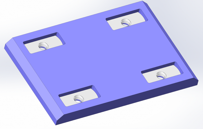
Wear pad design is critical for the success of your sliding project. The first thing to address is chamfers on the slide pad. There should be a lead in chamfer of at least 1/8 inch and no steeper than than 45° in the direction of motion. The wear pad should also be longer (in the direction of travel) than it is wide.
Narrower pads give an advantage in several ways. First they can reduce the number of fasteners needed to retain the pad. Second, you can get better material per sheet usage.
Finally and most importantly, you can place the loads where you want them better. If your inner member is a structural tube with corner radii, placing two pads on the outside is a far better design than one large pad along the middle. There is no benefit gained by pressing on the middle of a hollow tube.
Wear Pad Retention
Screw Retention Methods
Most wear pads are retained by screws. I highly recommend using this method on all your slide pads. The other main retention method is using an adhesive which may fail and prevents easy replacement of the pad. So, use screws.
Make sure there are at least 2 fasteners per pad and push the fasteners a close to the edge as possible.
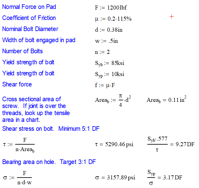
Perform a calculations on the wear pad screws to ensure that they have a design factors consistent with the equations below. If there a persistent problem insists, look into the design. You may have an interference or other issue that is causing higher loads.
There are two main ways to use screws. You can either insert the screw from the wear side of the wear pad (say that 5x fast) and add a nut or have the screw insert from the other side. Both have their advantages and disadvantages.
Assembling Screw From the Wear Side of the Pad
Inserting the screw from the from the wear side of the pad is great for two reasons. First, you can evenly distribute the load to the wear pad using a countersink fastener. This is important so that the wear pad has more contact area and won’t pull out of the material. Second, it allows you to have predictable head clearance on your fastener.
Unfortunately, you will need to access the head of the screw in order to change the wear pad. This can be an issue for service since you many need to remove the entire inner section to have access to your screw heads.
The other main draw back is that countersunk set screws can get clogged with debris making it much easier to strip the head.
It may be necessary to fasten your wear pads in this manner if your inner section is too small to gain access to from the inside or if you need to fasten into a tapped hole.
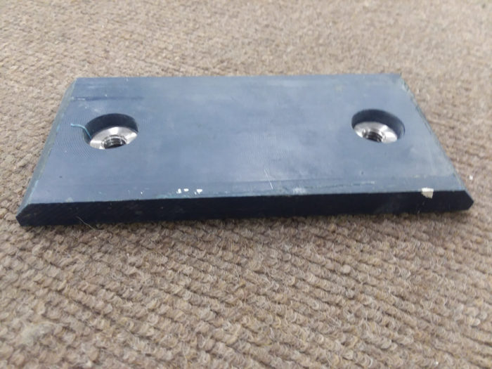
Assembling Screw From the Rear of the Wear Pad
The other alternative is to assemble a standard hex capscrew from the rear or back of the slide pad. This is my preferred method, but it has it’s drawbacks as well.
Do do this, we will need to add a retention method into the design of the pad. There are some steel hex inserts that can be pressed into round holes cut in the wear pads. The inserts have a tapped hole in them for the screws.
However, I prefer to use weld nuts because they won’t strip in the soft plastic like like the hex nuts inserts do. Using a small bearing press, you can press weld nuts into a hole that is slightly smaller than the weld nut. You can also add a few drops of super glue if you don’t trust your press fit.
I like this method because it removes the countersunk socket screw from the design and therefore access to the top of the wear pad. This translates into easy change out of wear pads for 95% of applications. A side benefit is that you don’t have screw threads sticking out to catch your sleeve or cut you.
Assembling a standard hex head capscrew from the rear of the slide pad is my preferred method.
The major downside is that you will need to plan for clearance on the screw more carefully. This roughly translates into the weld nut being recessed 0.25″ (6.3 mm) from the wear side of the pad. I get to 1/4″ because there should be at least 1/16″ (1.6mm) for wear and screw thread sticking out. Most wear pads will be retained by screws that are less than 1.00″ (25mm) and come in increments of 1/8″ (3.1mm) for when we need to set up in size. The sum of these numbers is 1/4″.
Assembly can be an issue especially if shim pads are needed. The assembler will need to know when it is necessary to increase or decrease the screw length. Be sure to stock fasteners in 1/8″ (3.1 mm) length increments.
Entrapped Retention
Also known as U-shaped retention, entrapped retention is a method that allows for a larger bearing area for the wear pad to contact. We do this by adding another piece to the assembly. As shown below, the wear pad will have a side profile in a U-shape (hence the name) where a metal, usually steel, bar will fit. The steel bar is retained by two or more screws.
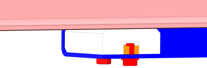
You will notice that the wear pad is not direct fastening of the wear pad to the anything. It is held in by gravity so it should only be used in applications were there is constant contact and gravity will keep it in place. Futhermore, you will want the width of the U to be just larger than the steel plate for easy assembly. However, you don’t want it too big in order to minimize impact loading when the direction of travel reverses. Usually 1/16″ (1.6 mm) is adequate to accomplish both. Much more and you can start hearing chatter as well.
This type of joint is used for highly loaded joints where you cannot insert enough screws to get your bearing area to an acceptable level.
Screw in “Puck” Design
The screw in design is my least favorite. I personally have never tried it and have very little experience with it. The puck design is used for less loaded bearings which are usually on the side of the extension.
The concept is simple: thread the outside diameter of a piece of round UHMW or Nylon. The diameter may be 2 (50mm) to 3″ (75mm) to get enough bearing area. You can then machine a smaller hex on one end to turn it. A less expensive option is to drill two holes in the end and use a spanner wrench to turn the puck.
The mating component will have the same thread as the puck and you screw it in until the depth you want. One neat thing about this design is that as the puck wears, you can screw it in a little further thus replenishing the wear pad.
The major problem with this is that the pucks have an tendency to loosen easily and fall out. You then are at risk for metal on metal galling. To minimize this risk, I recommend that you have at least two pucks per joint.
You can also use retention methods such as thread locking compounds. Be sure they are plastic compatible. You can also try jam nuts with low torque or a plate that will fit over the hex and prevent it from rotating.
Contact Stress
The pressure on a standard linear bearing is super simple to calculate using the traditional formula pressure = force / area. It is important to use only the area in contact with the other surface. As a result, the area will be reduced by the lead in chamfer and holes for retaining screws.
You’re 3D CAD software should be able to calculate your contact area by selecting the surface. Easy peasy.
In general, I look for the maximum contact pressure to be 10% of the tensile strength or a 10:1 design factor. I do this because I assume that only 50% of the pad is actually in contact with the mating surface and then add a 5:1 design factor so that the wear rate is minimal.
Low Bearing Pressure
Noise is always an area of concern with slide pads. With sliding wear pads, the noise usually comes from a wear pad that makes light contact.
Noise usually comes from a wear pad that makes light contact
The Whale (Sometimes I still hear it in my sleep)
At a previous job, we had an articulating cylinder (rotational motion) that had two cylindrical bearings. One of the bearings was directly under the load needed to articulate the cylinder. The other bearing was equal sized but had nearly no load on it.
As a result, the no-load bearing sounded like a irate whale and could be heard from a quarter mile away. No joke…it was loud!
The solution was two part. First, move both bearings laterally a little so that the load was distributed better. Second we narrowed up the no-load bearing so that the pressure increased. The noise vanished!
Recommended Minimum Design Pressure
I tell the story so that you think about bearings in terms of the maximum and minimum loads while moving. As mentioned, I look for the maximum contact pressure to be 10% of the tensile strength or a 10:1 design factor. I do this because I assume that only 50% of the pad is actually in contact with the mating surface and then add a 5:1 design factor so that the wear rate is minimal.
I also look for the minimum load on the bearing to be 2% of the tensile strength or 1/5th of the maximum allowable contact load. Keeping this minimum load in mind will increase your chances that noise will not be an issue.
Contact Stress Through Tubes with Corner Radii
If you are using a steel square tube with corner radii in your sliding joint, you are starting at a disadvantage. Since the internal radii will be 2 – 3 times the wall thickness, you are automatically causing the corner and side of the tube to take moment. This will limit the amount of normal force that the tube section can take due to localized buckling.
Ideally you want the load from the pad to be able to be translated directly into the vertical member of the tube. This is the best design for stress flow because it eliminates localized buckling.
There are basically two courses of action to increase the strength. First you can thicken the tube wall. Doubling the thickness of the wall will quadruple the strength of the corner. However, it adds a lot of weight so it might be impractical.
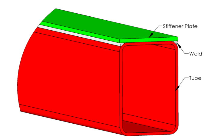
The other option is to add a plate on the contact side of the tube. This adds less weight than thickening the tube wall. Sometimes it will allow you to thin the wall up leading to a reduced weight.
The downside is that you will need to weld the plate solid for the entire length where contact is made. This can be a lot of weld and you will probably need to worry about weld distortion. One way to avoid this is to make them in pairs with the added plates touching.
Plug welds should also be added down the length of the section to allow the added plate to act more like it is one solid piece with the tube. A plug weld should have a diameter of at least 1.5 times the thickness of the added plate. Be sure to grind it flush so that you don’t have high spots for the wear pad to run over.
Sliding Speed and Duty Cycle
Wear pads are friction members. If extending under load, they produce heat! Since they are usually plastic, they can melt pretty easily. They need time to cool off in between cycles. If your PV (Pressure * Velocity) is higher than the material allows you can usually get away with it if your duty cycle is less than a 25%. Otherwise you will need to switch to roller bearings.
Also, the maximum speed of the tube is critical. Depending on your material speeds of up to 10 fpm to 25 fpm are acceptable.
Some manufacturers of wear pad materials will publish the maximum pressure, velocity and PV ratings. Experimentation in your application will be necessary.
For example, UHMW has a limiting PV of 750 psi * ft /min with a maximum velocity of 15 ft/min. Nylatron GSM boasts a much higher PV limit of 5500 psi ft-min
Torsional Loadings
Many extension aerial lifts have buckets that rotate from side to side causing a torsional load to transmit through the sliding joint. Whether or not you like it, there will be some amount of torsion on every extension joint.
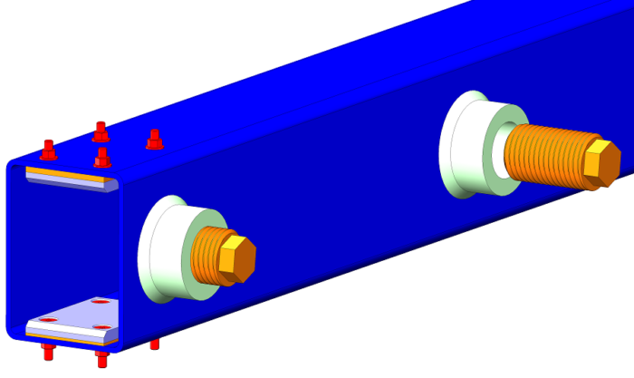
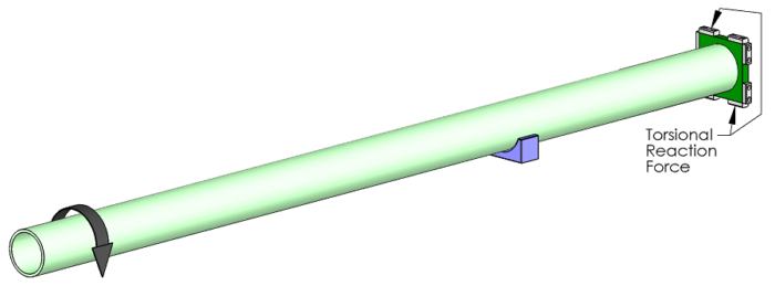
On round extension systems, there will need to be a separate system to handle this. Commonly, a rectangular plate will be welded or bolted to the end of the extension that is inside the outer tube. Wear pads can be placed on this plate to take the loading.
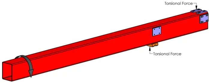
With rectangular extension systems, there is built in resistance to torsion. There are many ways to approach how to do this, but we need to always look at the worst case scenario.
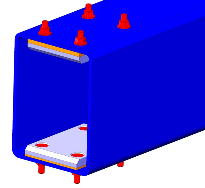
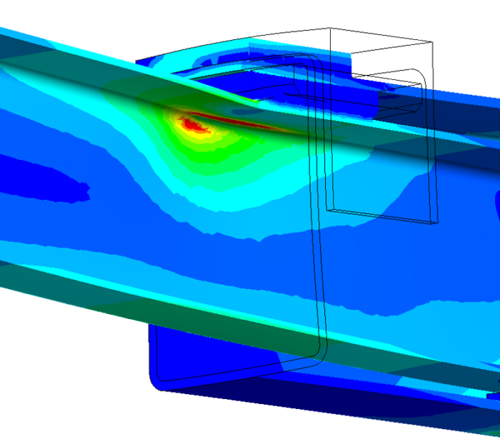
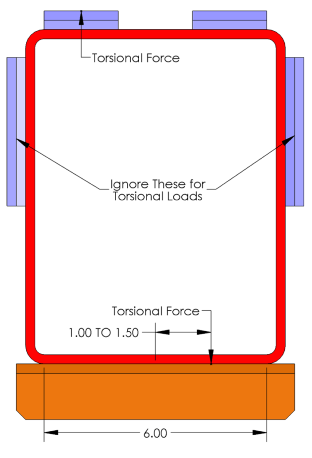
A good sliding joint will have the the torsional loading add to only the highest loaded pad on each end of the reaction. In most cases, the extension is taller than it is wide. This means that the the moment arm for resisting torsion will react on the narrow dimension of the extension.
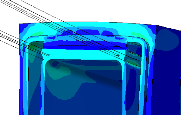
For example, the picture below has the two pads that will take the torsional load highlighted. One is on the outer reaction to the lower left and the other is on the inner reaction on the upper right. If the design had two wear pads, assume the pad is evenly loaded. If it is a single pad, assume the load can be offset to 1/6 to 1/4 the pad length off center.
This is the worst case. I like it because you will never go wrong here with insufficient retention or higher than expected loads. Sure other wear pads, like those on the sides, may take more load, but we are good engineers and plan on the worst case.
Wear Pad Placement
When planning your wear pad placement, you want to have them as close to the end as possible. The benefits are threefold: you minimize normal forces, which minimizes friction, which maximizes bearing life. Boom!
As an added benefit, placing the wear pad flush with the end will greatly help when aligning holes. This is a critical step in making your assemblers happy because they will be able to hold the pad comfortably.
If using a hollow inner tube, you will want to get the contact forces to the corners of the tube. This minimizes the bending load seen on the tube wall and reduces weight. The best way to accomplish this is by splitting the wear pad into two pieces and placing then as close to the corners as possible.
Planning for Manufacturing Tolerance
Shims
Most sliding systems are not designed to be perfect. This will show up when you mass produce the design. We need to have a plan going in. For most of us, this plan will contain shims. Great!
However, when we often fall short is engineering in a condition where we can still be too tight when there are no shims. Oops!
I have been burned on this one. Luckily it was found in the prototype phase and we were able to correct it before production started.
The solution is simple; always plan on using at least one shim on each pad. I usually plan on 1/16″ (1.6 mm) to 10 ga (0.1345in / 3.4 mm) per side. This gives me plenty of room to adjust the shims as needed.
Crooked Sliding
Many times, you will find that the inner tube is crooked in the outer tube. Not only does this look bad, you can actually load up your bearings higher than expected.
If you think about it, this will always happen to some level; even if you need a microscope to see it. This is why I recommend using the 10:1 design factor. The good news is that the wear pads will wear in the high contact levels and distribute the load to more of the pad over time.
One solution to this is to have machined shims that are faced at an angle (wedge shaped). This is very expensive to manufacture but will work. Another solution is to have two different thickness shims under the wear pad. This works best for shims that have at least four screws and with small changes in thickness.
Assembly
This is where most young engineers blow it, myself included. You have to have a plan for assembly! Here are some things to consider your wear pad design.
- Not thinking through how the unit is assembled – Oh boy has this burned me! Tube in tube joints usually have a specific way that they need to be assembled. You need to go through each step in the assembly process one component at a time and insure that each step can be completed. I’ve known many people who can do this in their head. For the rest of us, hiding parts in 3D CAD will do the same job.
- Not leaving room to tighten fasteners – There is nothing more frustrating than tightening a fastener by flipping a combination wrench over each time or only hearing one click on a socket wrench. Design in more room please!
- Reaching inside tube really far – If you need to reach inside a tube more than 18″ to insert a part, something is wrong with your design. I do admit that I have had the occasional design where a bolt spring was needed to install a carriage bolt. It is one thing to reach in to install a bolt, but another to have to hold it during torquing.
- Wear pad replacement – Your wear pads may need to be replaced from time to time. As you are assembling this, ask “How many parts need to be removed to swap out the wear pads.” It was always a requirement for me that the wear pads could be replaced by only removing a cylinder pin or other component. I liked to be able to slide the inner tube out the opposite end so that those wear pads could be replaced easily.
Awesome post! Keep up the great work! 🙂