Designing a roller coaster can be a tedious challenge. Where do you begin? So many decisions to make is daunting to anyone. We’ll, how do you eat an elephant? One bite at a time.
In order to design a good roller coaster, you must consider the proven track designs and select one. Also, consider the terrain available to make your layout unique. Finally, use design the layout so that it will give you the forces you want.
Common Track Types
If you look at modern roller coasters, it seems that each ride manufacturer has their own unique track design. Each has benefits and drawbacks for a backyard roller coaster.
This video explores some of the popular ones and I select one for my roller coaster.
Every yard is different so get creative on how to use it. Is there an existing structure that can be incorporated? Is there a small pond or pool? Trees you can miss or fly through? Think about such things as you start developing your track plan.
Laying out your course can be a daunting task. This spreadsheet will aid you in your design by removing most of the math needed for a successful coaster. The spreadsheet will allow you to calculate the velocity, energy and G forces at any point. I selected only the critical points, but you can add points every foot or meter if you’d like!
The main unknown here is your coaster’s efficiency. The Black Widow had a 6% coefficient of drag, but I only knew that after it was built. Unfortunately, I planned for 5% so the cart doesn’t make it all the way back to the station. I recommend that using multiple coefficients of drag for your design to ensure a complete loop.
Plan on a worst case 6.5% efficiency so that the cart makes it all the way back around. Then use a 4.2% to see if the ride becomes too violent for your taste. End up somewhere in the middle (5% to 6%) for what your actual coaster may do.
New to Solidworks? It is a complex and daunting piece of software. Let’s explore this powerful tool in 1 minute bites. We’ll start at the beginning, with sketches.
After multiple failures with the first drop, we are re-imagining the Black Widow. But first we need to make space and reuse some of the track sections.
Routine testing caused a failure in the same spot on the Black Widow backyard roller coaster. It is here by canceled. But hold out hope! We are going to reimagine it.
The 1990’s movie Speed is a classic! And it has some wonky engineering stuff in it too. Let’s separate fact from fiction and give some good engineering tips too.
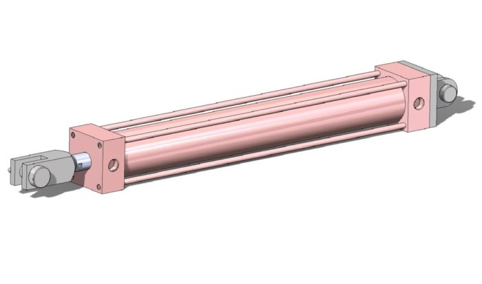
Pneumatic cylinders can work best in the fully extended or retracted positions. Midstroke position can’t be held due to the compressibility of air
If you have any experience using pneumatic cylinders, you know that they don’t hold a midstroke position at all. You design them to be fully extended or retracted. So, what if you need the cylinder to stop at a position in the middle? This is a very difficult proposition. Well, here is a trick to maintain two midstroke positions with high accuracy despite the load.
In order to hold a midstroke position using only pneumatics, place two cylinders of varying strokes barrel to barrel. When the stroke of both cylinders is added together, it should equal the total stroke required. To achieve the midstroke position, extend one cylinder while retracting the other.
A number of years ago, I ran into a situation where I had a pneumatic clamp. The clamp was high cycle and the client was concerned about air usage since they were nearing the system capacity. So, we wanted to keep the air usage a low as possible.
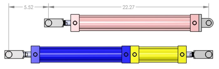
Using two cylinders, we can now hold two midpoint locations. Note the longer dead length of the cylinder. With 2″ bore cylinders, the dead length is increased by 5.52″
I noticed that the at each end of the long workpiece we needed a lot of clearance (about 12″) to unload the old and insert the new. However, when we were in the middle, we only needed about 2″ of stroke to make contact with the workpiece, making a total stoke of 12″. (We went with 14″ just to be safe). If each cycle was the full 12″ we would be wasting a lot of air when we only needed 2″ of stroke.
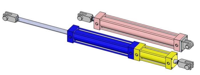
After scratching my head for a few days, I thought about using two cylinders, placed back to back. They would have strokes of 10″ and 4″. When were were changing out the workpiece, both would be retracted. Once we were ready to run, we would extend a 10″ cylinder. When we would clamp, we would extend the 4″ cylinder. Only the 4″ cylinder would cycle until the end of the workpiece when both would retract to give adequate clearance.
When we weren’t changing the workpiece, the blue cylinder (10″) was extended. We would then cycle the smaller 4″ (yellow) cylinder.
In this case, I only needed 3 positions, 0″, 10″ and 14″. But using this design, I would also have a 4″ position.
This design saved air usage and lowered operating cost, which lead to a very pleased customer. The system did require another valve to control the second cylinder, a little more login in the PLC and some additional support. These additional upfront costs were quickly surpassed by the savings from reduced air usage.
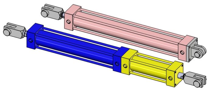
One note about this design, is that the cylinder barrels will move, which can make hose routing difficult. Be sure to leave room for flexibility or use a hose carrier. If your cylinders have different strokes, mount the shorter stroke cylinder to the base of your apparatus. This will minimize the distance the hoses move.
Another note is that it works well in a situation where the cylinder has a pinned clevis at each end. If you are intending for the cylinder to be mounted at the base as a fixed joint, it won’t be able to support the weight of the cylinders and is likely to buckle or bend. As a result, you will need to support the cylinder barrel with some sort of sliding mechanism.
How do I attach them?
There are several ways to attach the cylinders together. The main way is to add in two identical plates (flange plates) between the cylinders. The plates will have countersunk screws that mount to the base of each cylinder. They will then have another bolt pattern that will allow you to bolt the plates together. Many cylinder manufacturers have these as a standard part.
If you want more of a challenge, you can attach them by replacing the tie rods with longer ones. This is a riskier operation and should only be done by a qualified person. Take the tie rods out of each cylinder and then insert the longer rods. Torque the rods evenly using multiple passes. This process can be very tricky if one or more of the end blocks is tapped and needs to be drilled out.
Leave Your Comments
If you have ever designed a system that used two cylinders like this, let us know in the comments. What were the benefits? What were the challenges?