The real challenge of engineering is making good decisions especially when we don’t have all the data.
Here are several keys to making a low stress decision:
Have a clear objective
Set a short time limit
Limit the number of decisions you make
Don’t make the same decision twice
Know when to bring someone else into the decision
Don’t overthink the problem
Choose the simpler solution
Commit now, but decide later
Use a decision matrix
Sleep on it
Pick at random
Embrace Failure
Yes, as an engineer, you will make lots of decisions every day. Most of these decisions are quick and easy so we won’t discuss those here. Our education has taught us a lot of knowledge and analysis techniques. Sometimes those tools lead us directly to a solution, but many times, there are two or more equally good solutions. This is where experience and wisdom come into play.
In the engineering world, we are definitely caught between being the first to the market and having a quality product from the start. Poor quality can be improved upon, but there are cases where extremely poor quality has given that market a black eye. One example that comes to mind is the use of fiber optic controls on outdoor equipment in the late 1980s. The quality of the system was so poor that fiber optics were pretty much a four letter word until all those familiar with it retired. In the meantime, computers and other related technology made significant strides, but still could not be used in this market.
I’ll be honest, there are times when I don’t want to make a decision, but it needs to be made.
Let’s explore each of these items.
1. Have a clear objective
This by far is the most important step in making a decision. The better you can describe what the ideal solution is the easier your decision will be. If you have no idea what a good or bad idea looks like, you will never get close to making a decision. Spend time analyzing exactly what works in similar designs as well as what won’t work and be very specific. Come up with a list of important criteria and set weights to them.
Typical criteria are:
Effectiveness
Robustness
Simplicity
Cost
Time to implement
One part of an objective that is often overlooked is how the solutions line up with your company’s values or mission statement. Be sure to consider this with every decision.
2. Set a time limit
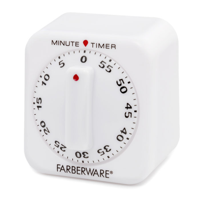
First off, this is more for little decisions although having a time limit of something like, “I will decide this by the end of the week”, will work as well. Having a time limit prevents you from procrastinating or spending too much time on small details.
If you are like me, I hate it when I come back from vacation and there are now 200 emails that I need to sort through. This is precisely where the timer comes into play. I will look through each email for 15 to 30 seconds at most. If the item can be completed in that time or added to a list etc., I do it. Then the email is archived or deleted. If it requires more time, I mark it as unread and leave it alone.
In about 30 minutes, I could get through all 200 emails and be left with around 20 to 40. I would then repeat the process and give somewhere between two and five minutes for each email. This generally left me with usually 1 to 5 emails that would take a considerable amount of time to handle. On average, I think that I could handle the overwhelming majority of emails in 90 minutes.
3. Limit the number of decisions you make
Honestly, we all make too many decisions every day. I once saw a number of 35,000 which makes sense, but wow – that’s a lot! Luckily, the vast majority are very minor and can be ignored. However, if you are continually making many large decisions each day, this will likely lead to fatigue.
If this is the case, you need some help. If you have the ability to delegate, do so. If the person you can delegate to isn’t qualified to make a decision, have them do research so your decision is easier. If you can’t delegate, talk to your boss. He or she may be able to help.
4. Don’t make the same decision twice
This one is a sneaky son of a gun. I you have decided on a matter, but haven’t committed to it, you are going to keep rethinking the decision until you do. This is the very definition of stress. Once decided, lock it in immediately and forget the other options.
5. Know when to bring someone else into the decision
This is easy, but often overlooked. Make sure that you have a trusted group of advisors that you can bounce ideas off of. They don’t even have to be engineers, in fact sometimes it is better if they aren’t.
Let me explain. New and untrained eyes on the problem will force you to explain the problem in great detail and how each potential solution addresses solves the problem. There have been multiple times where just in explaining the problem to someone else, the solution presented itself.
6. Don’t overthink the problem
Paralysis by analysis is a real thing. Sorting out what data is important or not is imperative. Often time having less data is more helpful in making a decision. In general, engineers want to be 100% confident that our solution will work, but that is never the case. We can always run more tests, try other solutions and consider more variables, but we are just prolonging the decision. Know when you have enough information to make a decision.
7. Choose the simpler solution
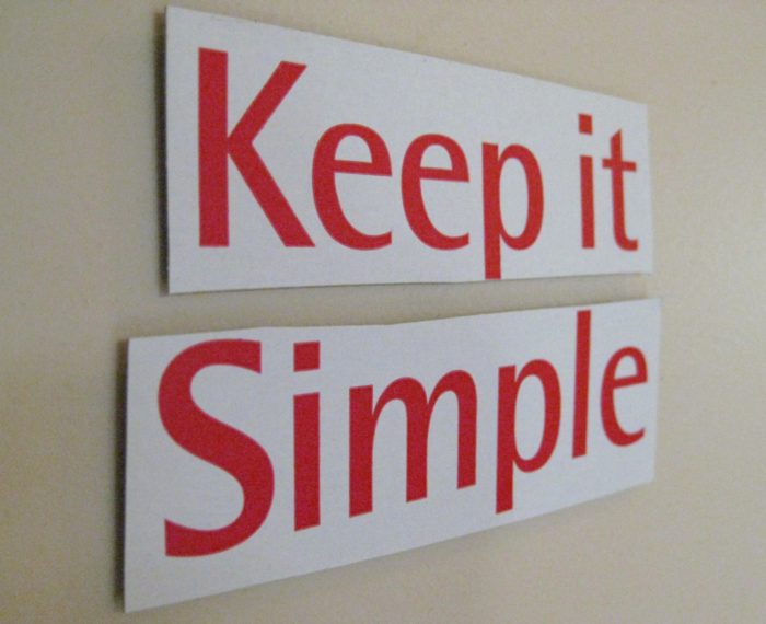
Yes, if you have two solutions that are pretty much equal, choose the simpler one. In my experience, there is less that can go wrong with simplicity. I know the adage of the engineer is “if it isn’t broke, it doesn’t have enough features,” but not everything needs to have every feature. I prefer “not broke” over features every day.
8. Commit now, but decide later
This is an interesting approach that I was just made aware of recently. Make no mistake, this is not procrastinating, but rather a method of getting you in the habit of making quicker decisions without the fear of regret.
It works like this: your boss asks if you have decided whether Solution A or Solution B is the way to go. Solution B is clearly the better choice, so you say we should proceed with that. However, you also add that you would like to run a quick test on Solution B to confirm that it is the best choice.
What you have done is instill confidence in your decision to your boss, but left an ‘out’ in case the test fails. We do this when buying a home where we put a little money down at the offer, but we can back out after we run our tests, namely a home inspection, before we close. There is tremendous benefit in expressing commitment, but deciding later.
I will caution you that your test should be brief when compared to the decision timeline. Otherwise, you are just procrastinating.
9. Use a decision matrix
A decision matrix is a tool that allows you to visibly weigh multiple criteria against multiple potential solutions. This is done by assigning certain weights and values for each solution against those weighted criteria. When done right, either by yourself or with a group, certain solutions will come to the front and others will retreat.
However, if you have one option that scores slightly higher than another, it doesn’t necessarily mean that it is better. This is a tool and it still needs interpretation by you, a qualified engineer.
10. Sleep on it
Ok, this also is not procrastination as long as you set a time limit. Our brains are amazing computers, but we need time and often a change of scenery to process the decision. Sleep and “windshield time,” (the time spent driving to and from work looking through a windshield) are miracle workers when it comes to clearing out your brain and making good decisions.
11. Pick at random
Yes, it seems ridiculous, but if all the solutions are equal, pick a solution at random. Write the option on sticky notes and pick them from a hat.
12. Embrace the Fear of Failure
We knew this one was coming. Yeah, we are all going to make a bad decision and some of them will be big ones. Notice the title says, “the FEAR of Failure,” and not failure itself. Failure is not eminent! This is often the cause of dragging our feet or not making a decision at all.
Personally, I have a goal to fail for one reason. When you fail you tend to learn more, after all, you will learn more from one failure than from a thousand successes.
Engineering disasters like the failure of the Tacoma Narrows Bridge or the oil spill from the Exxon Valdez taught us far more than a hundred good bridges or oil transport successes. My point is that failures are something we learn from and we should not put off making decisions because of fear. Failure will occur, give it a big hug and learn from it.
There have been several times in my engineering career that I have needed to limit the force a mechanism can produce, but still allow for unpredictable amounts of deflection. This is very useful in cyclical testing when the test piece needs to have a certain load applied to it over and over. Usually in situations like this, you want to be able to setup a test machine and let it run continuously without the need for babysitting it.
Generally speaking for an application like this, using a rotating motor with a cam makes the most sense. The cam would then be attached to the test piece as shown. However, I can only produce the correct force when the test piece, link, motor and cam are all perfectly spaced when the cam is at its apex. Even if I could get this right, the nature of machines is that they wear.
If my test component needs 100 lbs. applied repeatedly, I could set that, but by cycle 1000, I could have worn multiple parts and lost most if not all my initial force. The cause of this is simply increased distance or deflection. At this point, you could design a complex control system to monitor the force and make adjustments to the spacing or the cam offset, but that sounds like a lot of work and money to me. I’m just not interested in that and you shouldn’t be either.
So here’s the solution:
We need to have a way to insert some flexibility into the system. The obvious place is to look at the link. The solution is to replace a fixed link with a rod and tube connected by springs. Yes, springs are the key to all this. So we may remember that a spring follows the formula F = k * x. Where F is force, something we are interested in, k is the spring constant and x is the deflection.
The mechanism shown below consists of several parts: the outer shell, the springs, the rod and some hardware. It is a pretty simple mechanism, but the most important and difficult part is selecting the springs.
What kind of springs do I use?
This is a great question. So this device will be used in tension, so we will need to use compression springs or perhaps Bellville washers. If springs are chosen, be sure to select closed and ground so that they can stack easily. To select the right spring, we must first decide what our load range is. Generally this should be about +/- 5%, but we can bias this. In our example of a nominal 100 lb, are we ok with 95 lb. to 105 lb.? We could also bias this to be 100 lb. to 110 lb.
For this case, we will have the maximum load at 110 lb. We should definitely select the maximum loading of our spring to be at least 10% more than our capacity. We also want to look for a relatively low spring rate. In this case I looked at McMaster Carr and selected 9657K451. This is a spring with 124 lb. max load, a spring rate of 127.3 lb. /in, a free length of 3.50 in and a compressed length of 2.49 in. This spring should do fine.
How do I plan for deflection?
To estimate the deflection, be sure to consider all the components involved because they will all add up together. If we estimate this at a quarter inch, I would plan to double that in our calculations. With this apparatus, it is much easier to minimize deflection than to add.
In this case we will use half an inch as our delta, Δ. So let us look at what kind of deflection we anticipate. Using the spring equation, we will solve for x using the differential force required.
110 (lb.) -100 (lb.) = 127.3 (lb. / in) * x (in); x = 0.078 in
As you can see, there is very little deflection. What we need to do now is put multiple springs in series so that the deflections add up, but the force remains the same. We can now calculate the number of springs needed.
Δ = 0.50 in = n * 0.078 in; n=6.4
So we will need seven springs in series to give us the characteristics we want.
Designing the Housing
We are ready to start designing the rest of the machine. From our spring catalogue, we see that the outside diameter is 0.625 in and the inside diameter is 0.385 in. For the rod, threaded rod is the best choice. It is easily available in a variety of sizes and grades. This will be the piece that we set our target force with so we want the infinite adjustment it gives. The logical choice here is using 3/8-16 threaded rod because it is 0.010” smaller and provides a great pilot for the springs. The pilot is important because it ensures that the springs stay stacked properly.
The outside housing is a little more difficult.
We have to be strong enough to carry the load, be able to assemble it and most important, we don’t want to have to machine a bunch of parts. The best solution I’ve found is using threaded pipe with pipe end caps. It allows for items to be assembled and requires no additional bolting or machining.
In our case, a ¾ schedule 40 pipe will work well because it has an ID of 0.824 in. Since we are using seven 3.5” long springs (24.5”) pieces, we need to have at least that length of housing, or do we? Ok, so we can cheat that a little in this and many other cases. In this case, I would choose a 2 foot length of pipe since it is commonly available in most hardware stores.
A little fabrication
So we now need to drill a hole in the end of each end cap, I recommend doing this on a lathe to keep the centers aligned, but in a pinch, doing it by hand will work. Just make sure you mark the center well and punch it first. The hole should be sized slightly larger than the threaded rod.
Assembly and calibration
From the drawing you can see that a few nuts, washers and eyebolts complete this assembly. If eyebolts don’t fit your application, you may need to do a little more engineering work. Once assembled, you can calibrate by hanging the housing from the crane or other structure.
Apply a known weight, in our case 100 lb., to the end of the threaded rod. The rod will extend until equilibrium is reached. Adjust the two nuts on the rod until it is snug with the housing. Jam the nuts together to ensure they don’t move. You can then add another 10 lb. to the existing weight and see how much the nuts extend. It should be just less than the ½” we planned on.
If you would like to build this version of a force limiter, this is the bill of materials to do so. All of these parts are available at McMaster-Carr.
A few final thoughts.
I mentioned using Belleville washers instead of springs. While Bellville washers will work, you can really only use them with very small deflections. A good candidate for this application has a deflection of about 0.008 in at rated load. This would require around 600 washers to get the ½ in of deflection that we needed. It would also cost and weigh much more and have a longer length. It is recommended that Bellville washers only be used with deflections that are less than 1/16 of an inch or less.
It is recommended to use a rubber washer in between two larger washers on the threaded rod. When the link is unloaded, it will make a loud thud otherwise. I realized this on the first one I built when we needed to run a test that lasted several hours and it annoyed my fellow coworkers (not to mention the headache I got).
Finally, I recommend using this in only tension applications. You can use it in compressive applications but you need to worry about buckling and eccentric loading. This is a headache due to all the calculations and tolerances you will need to consider. You just don’t want to go down that road.
If your application needs to be in compression, I recommend getting a cylinder and maintaining constant pressure on the extend port. The other benefit is that if you use a cylinder, you can also make a simple controller for it to cycle the load as well.
Conclusion
In conclusion, a force limiting device like this is easy to design, assemble and fabricate. It can make life much easier in situations where you need to apply controlled loads repeatedly. You can also impress your friends with your smarts at the same time.
Best Guide to Understanding SAE Shafts and Mounting Flanges
It is not uncommon that we will need to couple pumps, motors and/or engines together. Jaw-style couplers help with joining shafts together. With the use of these couplers, we can adapt and fit many different types of shafts together, but interestingly, there are so few choices! Granted, there are lots of choices in the catalogue, but it seems that there should be many more shaft sizes, spline cuts and keys to choose from. Why aren’t there more? Also, what about the outside of the parts? They look like they were designed to be mated with something.
Your questions are not unfounded. There was a standardization that took place years ago. SAE led the way with standardized shafts and mounting flanges in SAE J744. The standard takes a seemingly infinite number of combinations and boils it down to a manageable number of combinations. The fewer the choices, the easier it is on engineers. Plus, manufacturers can often bring a product to market quicker since there aren’t many custom options.
Mounting Flanges
The Society of Automotive Engineers (SAE) has standardized the mounting flanges for hydraulic pumps and motors using a letter codes and the number of bolts used. The sizes are already designed to be able to properly carry the load with medium strength fastener (Grade 5 or equivalent)
SAE J744 specifies the flanges by a letter and a bolt count. In a two bolt pattern, the two bolts and center pilot are all in line. Two bolt flanges (black) come in AA, A, B, C, D and E configurations. Each one gets successively larger. The four-bolt ones have the center pilot surrounded by four bolts arranged in a square around it. These four-bolt (blue) configurations are available in B, C, D and E configurations. These flanges are constructed so that the center pilot will take the main x-y loads and the bolts only take the torque load. Below, is a table for the two bolt configurations. It contains the pitch circle diameter, PCD, which is the diameter of a circle drawn centered at the pilot and intersects the center of the bolt holes. It also has the size of the bolt holes and the pilot diameter.
Keeping your pump and motors on the same center and parallel is critical and often difficult to do. It can mean the difference between a long-lasting system and one that constantly needs maintenance. The example here, a log splitter, is almost exactly how not to do this. Let’s take a look at several problems:
The pump (left) is mounted on a thin piece of flat steel and cannot be adjusted for angularity.
The motor is mounted on a piece of wood. As temperature and humidity change, so will the height and angle of the engine.
The aligning of the shafts is entirely done by positioning the engine. There is limited flexibility. Washers were used to shim and they have discrete shimming heights which limits adjustment.
Even if we get all of these things perfectly aligned, which didn’t happen, if the jib is loaded to this side, the stiffness of the frame causes these to shift. Each loading of the jib changes the alignment if only for a few seconds.
This is not ideal and will definitely wear out the spider coupler faster. However, there are three options to get great alignment with a pump or motor.
If you go the route of designing something yourself, make note that it must be machined after any type of welding. I’ve tried to create weldments that use fixtures and heat-controlled welding processes to make pre-machined parts align. It just doesn’t work. Many times, it takes a large weld just to carry the required torque load so heat can only be minimized to a certain point. I’ve also had parts warp in the heat of a powder coat oven. No, if you want to design an interface yourself, it needs to be post-machined or machined after welding. Designing something yourself is a good idea for large run quantities and custom interfaces. If this is a ‘one off,’ a much better choice is to:
Buy a pre-machined coupler
Many times you can buy a pre-machined cast aluminum coupler if you are coupling an electric motor or gas engine to a hydraulic pump. Grainger, McMaster Carr and many others have these products online. They are wonderful because they ensure that the shafts will lineup perfectly and have an added safety feature. They usually shield all the way around except for a small opening so that you can tighten set screws in the jaw coupler. Some even have options for a plastic or rubber plug to fill this hole. I always opt for this option. Be sure to mount with the opening on top so that the plug does not fill with water and debris or the vibrations cause it to fall out.
Shaft Standardization
SAE has standardized shaft configurations to use keyways and splines to attach components. This limits the number of choices for each shaft size to one key and one spline. This makes it easy for the customer to specify mating components and the manufacturer to minimize component configurations.
You may have noticed that I skipped over close coupled arrangements. I did that because I wanted to discuss SAE shafts first. We will address that later in this section.
Shafts come in two varieties: Keyed and splined. We are probably all familiar with keyed shafts because this type is predominant in the industry. A keyed shaft has a small recess where a key is placed in. This assembly is then inserted into a hub. The main purpose of a key is to transmit torque, but prevent larger component failure when things go wrong. Keys are made of high strength steel, so if the key does break, diligently inspect all aspects of the system before replacing. Also, if your key breaks, be sure to inspect the shaft and hub for damage. Rolled edges from a broken key simply will not work correctly and must be replaced.
Keyways are designed in proportion to the shaft diameter. The intent here is to offer the maximum strength on the shaft while balancing the shear stress on the key. To put it another way, if we enlarge the key, the shaft will be inadequately designed. If the key is smaller, it won’t be able to transmit the rated torque. If you are designing a shaft or hub for a key, be sure to consult your Machinery’s Handbook for tolerancing guidelines.
The keys can be rounded (shown on shaft), square or a ‘woodruff’ cut (shown). As with anything, you can actually have many sizes and variations of each one including; oversized, undersized, stepped, and high profile. A stepped key will adapt between a shaft and hub of different sizes.
These shafts come in letter sizes A, B, C, D and E with double letters AA, AH, BB and CC. Each one specifies the shaft diameter, shaft length and total length. The key width is also specified and the depth is ½ of the width.
A splined shaft is much different. The full description is SAE 30° involute spline shaft, but in practice if you say splined shaft everyone will know what you are talking about. In appearance, they look like gears and essentially that is what they are. As you can guess, they do not have any mechanism to deal with over torque like a keyed shaft does. So these also have the same SAE letter codes available as a keyed shaft. A sizing table will have the spline details, nominal diameter and total length. Spline detail are displayed as 11T 16/32 DP. This is similar to how a gear is specified. In this example, the spline has 11 teeth and 16 teeth per inch of diameter (DP, diametric pitch). I’ll be honest; I do not know why the 32 is there. It seems redundant to me. The bottom line is this; if the teeth and diametric pitch match, the shaft and hub will fit together.
Yes, finally to the close coupling. This is when we fit our pump or motor to have either a splined or keyed hub instead of a shaft. This allows us to eliminate the entire issue of shaft alignment and jaw couplers by inserting the electric motor shaft inside the pump. In the image here, you can see that the pump is directly connected to the motor and there is no housing or coupler. This is a great option if you are driving multiple pumps from the same power source. In this case, you can have the pump that attaches to the motor with a hub on one side and a shaft on the other. You can then attach your second pump. Granted, having a hub instead of a shaft is more expensive on the front end, but it may end up paying for itself quickly if you can eliminate jaw couplers, machined framework and the time it takes to assemble.
In figuring out the specifications of our parts, SAE has helped by laying out the information for us. A very quick web search will provide you with the tables of all the shaft and mounting information. All that needs to be done is to answer these questions:
What kind of shafts are available components that fit my needs?
Which mounting bracket options are compatible?
Can I close couple this?
One last word of advice when working with couplers and shafts: Remember to always use anti-seize between the two faces in order to prevent any rust or corrosion. It is more than likely that you will need to remove or separate these parts at some point. If these components rust together, you might as well throw them away. You can try to pry them apart or use heat, but it is more than likely you will damage the internal components of your pump and motor in the process. Please, use the anti-seize. It is inexpensive and available in any auto parts store.
In Conclusion
There has definitely been a lot of information discussed here. After reading this, you should be able to:
Know good and bad ways to couple a pump and motor
Understand that shafts and flanges are standardized
Find and interpret the SAE tables and to ensure your pump and motor will match up
Understand the benefits of close coupling
If you can understand these basic things, this will put you ahead of your peers in designing hydraulic systems.
To quote my mentor, C. Marvin Franklin, “Bolts are Magic.” This is true! In the world of engineering, bolts simply are magic. They allow us to complete many projects and serve us in a variety of ways, which are vital in everyday applications. They can be used for a variety of applications ranging from easily removable components to semi-permanent structures.
Understanding the load and selecting the correct grade of bolt are essential for a strong bolted joint. Using corrosion resistant platings like yellow zinc and ovulated lock nuts will keep the joint strong and tight.Installing the washer with the smooth side toward the bolt head is also necessary for a joint that lasts.
Here is how bolts are magic: Essentially, bolts act as rubber bands holding together plates through applied tension. For example, let’s say I have two plates bolted together using a hex-head screw and nut. When we tighten the screw, the two surfaces will be pulled together. This in turn puts compression on the interface and tension in the bolt. We are now in a static condition with constant stresses for all eternity. Now, let’s start pulling those plates apart slowly. As we pull, the tension load in the bolt does not change until we pull more than the bolt’s pre-load. To get to specifics, if the bolt had a tension load of 2000lbs, we would be able to pull these two plates apart up to 1999lbs without changing the load on the bolt at all! Therefore, we would say they are magic and act like big rubber bands which allow us to put different stresses on the bolt without causing failure.
Fatigue life – Why is this important?
Let’s take a moment to look at how this might work out in practical application. A common everyday example of this setup would be an excavator’s main rotation bearing. Let’s say we have a pedestal that is fixed to the track assembly, that is bolted to a rotary (or slew) bearing and the top side is bolted to the back hoe and cab. These bolts are usually spaced around the entire circle so that the load is semi-evenly distributed.
In this case we will assume that the maximum load on any bolt is 40,000 lbs. This most likely occurs when the excavator has just pulled a large boulder out of the ground at full extension. Now, let’s rotate this fictitious boulder continuously. As we rotate, we see the bolts load up to a max as the bucket of the back hoe is directly opposite. If we continue, the load starts to diminish until it gets to 0 lb. It will then be in unloaded as the plates will be in compression until it gets back to the other side. The red line in the following chart shows the force applied to a bolt as it rotates.
This is not a good situation to be in for a bolt. As you see, this is a non-reversing fatigue load and at high enough stresses, these bolts will fail. This is where ‘Magic of Bolts’ comes in to play. If we tension (torque) all the bolts to the blue line shown at 35,000 lbs., we now modify the cycles as shown.
Now, only the peak of the load shows itself in the cycle. The fatigue calculation still has the same number of cycles, but the intensity of the cycle is greatly diminished. However, while this is a vast improvement, it is still not how we would want an engineered joint to behave. The blue line above is the desired state. The initial tension load is set above the applied load so the fatigue cycles are reduced to ½ a cycle, (a cycle is defined as one min and one max) and the load never changes. Goodbye, fatigue! Yes, Magic!
So, not entirely true….
When I was studying for the PE exam there was a practice question which included a pressure vessel with a bolted end cap on it. The bolts were preloaded and then pressure was applied to the vessel. I had to determine the calculation of the force on the bolts which is force applied with a particular tension on the bolt. I had two plates that were bolted together, and the force applied never exceeded the preload. I thought this would be an easy problem, well…yes and no. My calculation took about 10 minutes to do and I went to the answer section. Their approach was vastly different and took four pages to solve. When it was all said and done, our numbers were less than 0.50% different. In bolted joints, as long as the preload is always higher, the simple approach should be adequate.
Grades of Bolts
Typical Bolt Head Markings
Have you ever looked at the head of a bolt and wondered, “What are those markings for?” Well, the markings on a bolt indicate two things, the grade of the bolt and the manufacturer. The manufacturer identification is a requirement from the Fastener Quality Act of 1990. Grades are an indication of the fastener’s strength and each one is successively stronger. For English bolts, the typical marking is shown in the first row. A Grade 2 is on the left, followed by Grade 5 and Grade 8. So, your first question should be, “why aren’t they marked with 2, 5 or 8 ticks?” Good question…and the answer is simple, aesthetics! None of these would look good having the appropriate grade equal the number of ticks. However, if you subtract 2 from the grade, it looks beautiful (Grade – 2 = # of Ticks). (It also makes me wonder why they didn’t rename the grades 0, 3 and 5.) After, Grade 8, you get into proprietary bolts that have no specific requirements other than what the manufacturer specifies. They are commonly referred to as high-strength or Grade 9.
The bolt strength is specified at the proof stress which is the point on a stress-strain curve where the material will return to its original length without any deformation. This is roughly 90% of the yield strength. Within a grade, there may be two different proof strengths based on the bolt’s diameter. A grade 5 bolt over 1.00” diameter has a proof strength of 74 ksi while 1.00 and under is 85 ksi. These values can be looked up easily in tables.
A metric screw will have different markings such as 8.8, 10.9, and 12.9. Simply take the first number and multiply it by one hundred and that gives you your tensile strength (8 x 100 = 800 MPA). Similarly, to find the yield strength, multiply both numbers together and multiply by 10 (8 x 8 x 10 = 640 MPA). Since there is only 1 digit of precision, the numbers get you close enough, but not exact.
Fastener Types
Bolts vs Screws
The bolts versus screws controversy is a trivial matter that causes a lot of headaches. I’ve been told several false things over the years. The first misconception is that screws are fully threaded where bolts have shanks. Well, what about really short bolts, are they screws? The second misconception is that a hex cap screw is only a screw when it has a circle under the head. Incorrect.
The truth is that the difference exists in the application of the fastener. A screw will go into a tapped hole, while a bolt will be used with a nut. I know, weird. I like to remember it this way, if it can only be torqued from the head, it is a screw. If you need some proof, go to your local hardware store. They sell lag screws (can only be tightened from head) and carriage bolts (can only be tightened from the nut).
Capscrews
Hex Head Capscrew
Capscrews are one of two major categories of screws. A capscrew is a type of screw where a tool is placed on the outside of it to tighten. The most common is a hex head capscrew, HHCS (shown above). But square head and 12-point capscrews are also fairly common. Thumb screws would also fit into this category.
These fasteners are measured by the diameter, threads per inch and length. For example a ¼-20 x 1.00 is ¼” in diameter with 20 threads per inch and 1” long. This fastener will take 20 revolutions to move 1”. The nice thing about capscrews is that it is easy to find the right wrench to tighten it with. Just multiply the shank diameter by 1.5. For example, if you were to use a half inch hex head cap screw then you could expect to be able to grab a ¾ size wrench to fit onto it.
The length of the bolt is measured from the bottom of the bolt head to the end of the threads. If your screw is long enough, it will have a shank. This is an unthreaded portion of the shaft. The length of the thread will always be twice the nominal diameter (d) plus a quarter inch. (2d+1/4 inch). For example, a ½” screw will have 1.25” of threads before the shank starts.
Socket Capscrews
The opposite of a capscrew is a socket screw. I like to joke that you tighten a hex screw with a socket wrench and a socket screw with a hex wrench. Funny, but not entirely true. The socket screw can come in a variety of drives; hex or Allen is the most common, but Phillip, slot, square, spanner, Torex, and their tamper resistant cousins are also included. These are all considered part of the socket screw family. Perhaps there is no other collective name for them.
If the fastener is tightened with a hex wrench, three things need to be noted. First, the thread classification on this is 3A (more on that later). Second, the fastener is grade 9 or high strength. Third, these fasteners are designed for a black oxide plating which, in my opinion, is the worst plating option.
When first developed, these fasteners were only intended for industrial use, hence the black oxide finish. The standards were written around indoor applications, they didn’t want to mess with multiple grades, so they made them all high strength. As the years went by, these fasteners starting being applied to outdoor and mobile equipment. To curb the poor corrosion properties of black oxide plating, other, thicker, coatings were introduced.
At the time of this writing, most vendors will not warranty certain platings on a socket cap screw. This is because of the interaction of the three things mentioned above. In the near future, I think that the standards will be rewritten to allow these to be made in more grades and thread classifications. I wouldn’t hold my breath, though.
Socket screws have a bit more variety in their function than the capscrews, so we will discuss them individually.
Socket Head Capscrew
Typical Socket Head Capscrew
The top of the socket head cap screw (SHCS) is different as it contains a recess for a hex. You will never see a different head with these. These are great for many applications that require tight spots as the diameter is 1.5x the shaft diameter. Also, you can counter bore the hole to make these flush with the top surface. Another benefit is that they can be used without a washer.
Button Head Capscrew (BHCS)
On the top of this screw you will find a rounded profile with the hex recessto tighten it. These are particularly helpful when you have other materials that need to slide over it.
Flat Head Capscrew (FHCS)
The top of this screw will have a flat profile with hex recess and threads. Depending on whether you are using metric or English, the top will be 82° for the English and 90° for the metric. The length of these fasteners is measured as the overall length.
Set Screw
This is basically a fully threaded screw with a hex recess. It is used when you want to lock rotation. Personally, I tend to avoid these, but they can be used in non-critical locations such as securing valve handles or bearings on a shaft. Typically, set screws are available with different types of points such as cup point, cone point and flat.
Nuts
Nuts are the basic counterpart to bolts and screws. Most folks do not realize that nuts have grades just like screws. Typically, these grades will be stamped on the nut and used to match with a corresponding bolt grade. The highest selling fastener is grade 8. Unfortunately, not may know this because the highest selling nut is a grade 5. For instance, if I take a grade 8 screw which will be between Rockwell C33-C39 the nut will be between C24-C36.
The distribution of load on the nut is important as well. In general, the load is distributed on the first four threads of the nut. This means that a structural nut needs to have at least four threads of engagement. If the nut is the wrong grade, it will take more threads to distribute this load. A standard nut does not account for this. Match your Screw and Nut grades. When mismatched grades fail, it will look like the nut is trying to be rolled inside out until the screw can no longer engage the internal threads.
Tapped holes
Similar to a nut is a tapped hole in a plate. The main thing to understand is that we need to accommodate hard screw with a softer parent material. We don’t want to have the bolt pulling the threads out. The way to do this is with proper thread engagement. On a tool steel which is a hardened material in the range of C25-30, I can get full strength at a depth equal to the diameter. So if it is a 0.50-13 bolt, I can use a half inch depth of threads. If I have a soft steel, like A36, A572 grade 50, A656 grade 80, and possibly T1, I would want to look at one and half times the diameter. If I use a cast material or aluminum material, I am going to use 2x the diameter. If you are going to use any other material that is softer than aluminum, you will need to bolster up the joint or add more fasteners to get the load lower.
Washers
Interestingly, many people do not realize that washers can be installed backwards. Since washers are only stamped from one side, a radius can only be formed on the top leaving a sharp edge on the bottom. Since washers are made with a small radius at the top, you can feel whether the sharp side or the radius side is present in order to avoid installing them backwards. If I look at a hex bolt it will have a slight radius between the head and the shank.
We want to have the two radii mate and avoid having the sharp corner of a washer poking into the bolt’s radius. This causes a dent and impedes stress from flowing from the shank to the head. Washers are available in both hardened and non-hardened materials. It is important to match high strength bolts to high strength washers. In practice, you may want to have a hardened washer if the washer has a large hole to cover or spans a slot.
In general, there are several different styles of washers.
USS (Large or Wide)
SAE (Narrow)
Fender (Huge washers that cover up imperfections, often used in sheet metal applications)
Split Lock (Sprung open, not recommended for structural joints)
Serrated (Star) washers – sheet metal applications; can scratch surface paint
Spherical Washer – This two part washer allows for angular adjustment if joint isn’t perpendicular to the fastener
Bellville Washer – These magnificent creations are cone shaped washers are the split washer’s “big brother.”
A Bellville washer offers more resistance to screw loosening because when tightened, it flattens the cone. These washers have other uses as well; I once designed a limited slip differential using a series of these. If you want more compression force, you can stack these as they would naturally stack. If you want more travel, you can stack them so that the top of the cones touch. You can arrange these in multiple ways so that you can get the system characteristics you want using standard off the shelf parts.
Threads
The thread of a fastener is of critical importance. This is the feature that makes a screw a screw and allows it to work. If there were no threads, there would be no screw.
Thread Pitch
A thread pitch is the number of threads per a unit length. English units are per inch and metric is per millimeter. The larger the number, the smaller the ridges of the thread. For example a 1/4-20 screw has 20 threads per inch. In general, there are two different types of threads for each size fastener: course and fine. Coarse threads are larger in size because of their low pitch and they have several benefits over fine thread. One benefit is that they are more widely available in different types of plating. It also speeds assembly time because less revolutions are needed from the tool to install it.
Fine threaded joints tend to be stronger because the root diameter of the fastener is larger. Sometimes, a joint that is just a little too weak can be made strong enough just by changing from a course to fine fastener. However, they tend to have the propensity to be cross threaded at install. If the joint is not perfectly aligned, the screw can go in at an angle and add a new thread pattern.
Thread Class
It is important to note that the internal and external threads have thread fits or classes. In general you want to have the same class on each thread, but they can be mismatched as long as a tighter thread goes into a looser hole. There are six categories of specifying a thread using a system of one number and one letter. The number is first and it represents the fit.
Class 1 – Loose – great for galvanized bolts, fasteners with thicker platings or easier alignment of components
Class 2 – Normal
Class 3 – Very tight, minimal clearance between the internal and external threads
The letter is either A, for external threads or B for internal threads. As an example, a 3A socket head capscrew can easily fit into a 2B tapped hole. Ideally, most of the time you will use a normal, class 2 tolerance.
Threading
In addition to class and pitch, the method of getting the threads on screw is equally important. For the greatest strength, using a die and cutting the threads is not the best way. If we look at the shank of our bolt, there is grain structure that passes down through it and allows the stress to flow nicely. Now if I were to cut these threads into pieces of rod, I would create disjointed grains that run a higher risk of shearing. So, what we want to do is roll the threads by taking two plates with the thread pattern and put the bolt in the middle and roll the threads. Although the grain line will compress, it is still there the whole time. This makes the stress more aligned and the threads, in turn, are much stronger.
Making sure a thread will stay engaged is essential to a good fastening system. Locking nuts provide a great mechanism to do this, but there are several other we will discuss.
Serrated Flange Nut
The first type is a serrated flange nut, which, when tightened has ridges that grab onto the parent material, providing a locking effect. However, these can cause issues with rust as the teeth which lock onto the material scratch away paint or other coatings.
Nylon Insert Lock Nut
The next type is a nylon insert lock nut or ‘nylock’ which looks like a regular nut, except for the crown on the top of it. The blue part shown is a piece of nylon is inserted into the crown. When the bolt is inserted, it interferes with the nylon causing it to lock the nut in place.
In all honesty, I do not like these nuts because if you use an impact wrench or nut driver that tightens quickly, it will melt the nylon and make it impossible to remove the nut. Well, you can cut it off…but you get my point. If the nylon and screw do become fused together, your joint may become loose over time. Unless you can see a washer move, there will be no way to ensure the fastener is under tension.
Oval Lock Nut
So my preferred locking nut is an ovulated (oval) lock nut. This is a standard nut where the top of it is squished to provide the locking mechanism. The most common is to have the squish (yup, technical term) on the top, but it also seen in the middle. The oval nut overcomes the deficiencies mentioned with the nylon lock nut. It also doesn’t interfere with the torque required to get proper clamping load, but you will need wrenches instead of your fingers to get it snug.
Castle Nut
Another type is the called the Castle Nut. These feature a taller nut with recesses, usually six of them. The intent is to tighten the nut until it lines up with a cross drilled hole in the recesses. A cotter pin is then inserted, preventing the nut from ever backing out. This nut also has a few short-comings. First, there is increased cost with cross drilling the hole in the fastener and requires additional time assembling.
The main reason I don’t like it is there is a good chance that when this is at the proper torque, the hole and recesses will not align. You will either need to over torque or under torque. I would consider using a castle nut only if it was an application where the fastener could be loose but cannot come out.
Micro-encapsulation
There are several locking systems which can be used alone or in conjunction with other mechanisms. A common one is called thread locking or micro-encapsulation. A locking compound, usually nylon is placed onto the screw itself. This type mechanically locks the fastener by pressing it against the side of the tapped hole. With these, you can torque them about three times before the patch is worn out and the fastener needs to be replaced.
Another type of thread locking uses an adhesive. A chemical adhesive is applied to the threads of a fastener just before it is installed and torqued. These fasteners need to be installed in a certain amount of time before reapplication is need. There are many different adhesives used and then are available in both permanent and semi-permanent formulations with the latter allowing you to re-torque the bolt.
Corrosion Prevention
A bolt’s number one enemy is rust, since the overwhelming majority is made of steel. Most steel fasteners have some sort of coating on it which will turn white or gray, but the type of corrosion that we are concerned with is called ‘red rust.’ The method for evaluating the time to red rust is by using a salt spray chamber. In this chamber, a fine mist of salt is sprayed on parts continuously. Once red rust appears, the test is complete and the hours are logged.
Generally, exposure to chemicals or other substances that cause rust within 50 hours is not a good coating for outdoor applications. Once you are able to get around 100 hours without rust occurring, then you are getting some good use out of that bolt.
In the salt spray test, the white or gray is a lesser type of corrosion that doesn’t directly lead to failure. It is simply materials other than steel corroding first. This corrosion order is based on the galvanic chart.
Galvanic Corrosion Chart
Different metals are more noble or rust resistant than others. When dissimilar metals are mated together, one will always corrode before the other. This is why underground propane tanks have a copper wire attached to a large chunk of zinc. The zinc will corrode before the steel in the tank will. Since our parent material is steel, to get the best rust prevention, we would want to use a substance that is lower on the Galvanic chart than steel. If we went to a more noble material like gold, not only would the fastener cost a fortune, but it would essentially rust from the inside out. We definitely don’t want that to occur.
The game here is to have a coating on the fastener that will corrode before the steel parent material, but also give plenty of time for it to corrode. Oh, and we do not want to interfere with the thread fit or fastener friction and it must look pretty at the same time. You can see that this is not an easy task!
Hexavalent Chrome Zinc Plating (Yellow Zinc)
For a long time, zinc has been the go-to material, but it doesn’t offer a great resistance to corrosion. It has been coated with trivalent or hexavalent chrome to increase the salt spray life. The hexavalent chrome version, also known as “yellow zinc”, offers far better protection, but it has landed on the RoHS list and will be impossible to get in the next few years. You may remember that the movie Erin Brockovich was about the use/misuse of hexavalent chrome (it’s a good movie, I recommend it)!
Zinc Galvanizing
Another method of rust protection is called galvanizing. This is essentially putting larger amounts of zinc at high temperatures on the fastener. It can be expensive and hard to work with as you must use a different torque for it and it is a Class 1 thread that requires special nuts. Unless you are looking at severe exposure, it is preferable not to use this material.
So far, all these materials are called organic coatings and are made by the process of electroplating. This process takes place when a beaker is filled with water and a piece of zinc material with the bolt is placed into the water. Beside the beaker of water is a battery with the positive terminal attached to the zinc and the negative terminal attached to the bolt. Eventually, the surface material of the zinc is deposited onto the bolt. Depending on how long you continue this process and the rating of voltage used will determine the thickness of the plating the bolt. Obviously, if you are making these by the millions, you aren’t using a battery and a beaker, but you get the idea.
Where We are Going – Inorganic Coatings
We also have inorganic coatings which are specifically designed to go on the bolt itself. These are made in the process called spin dip which is similar to mechanical plating. Some of the major players in this market are Geomet and Magni. Inorganic coatings tend to have a very high salt spray life upwards of 1,000 hours. However, it is important to note that they are thicker and can disrupt your friction factor on the bolt. These coatings are the growing trend in fastener technology and is the direction all major users of fasteners are headed.
Conclusion
In this article, we have explored much about fasteners, but we really haven’t even scratched the surface. Bolts truly are magic. They can hold parts together and eliminate fatigue. They come in multiple shapes, grades, threads and coatings. After reading this, you should be able to:
Identify different types of bolts and screws
Explain, briefly, how we can eliminate fatigue loadings in bolts
Interpret the head markings on a screw
Install a washer correctly
Identify some fastener locking mechanisms
All in all, bolts are wonderful things…when used right. That is where we are heading next. Read the following article where we will learn how fasteners fail and how to properly apply them.
How to Use Jaw Type Shaft Couplers – A Simple Guide
Jaw type shaft couplers are a lifesaver. These wonderful pieces of machinery allow for torque transmission between two different items and account for radial, angular and axial misalignment. It also has built in shock absorption that diffuses impact loads, like from reversing loads, and start up loads. Jaw shaft couplers do this by having a mechanism, the spider, to connect two jaws. One Jaw connects to each shaft and the spider slips between the jaws. Great reasons to use jaw couplers include the following:
Allow for some misalignment (let’s face it, it is tough to get shafts to align right!)
Thousands of options for shaft size, torque transmitted and spider material
No metal to metal contact
Resistance to dirt and oils
Nearly maintenance free
Smaller sizes are readily available (no 8-12 week lead times). You can even buy them on Amazon.
Fail-safe. If the spider fails, the jaws will still make contact with each other. There will be metal on metal contact there, so be sure to replace the spider when this happens.
Torque and Service factor
The first thing that we must do in selecting the proper jaw type is to calculate the torque and application service factor. Torque is relatively easy and straight forward to calculate. It can be done with the following formulas.
Pretty simple. Now that we have this, we need to look up the service factor from the manufacturers chart. Simply multiply the calculated torque by the service factor to get the torque needed to size the jaw. The service factor is an essential element that accounts for impact loads that will be seen on the coupler. For example, something powered by an electric motor will generally have a lower service factor than one powered by an internal combustion engine. This is because, especially for single cylinder 4 stroke engines, every other rotation contains an impact load when the cylinder fires. Electric motors don’t have that.
Every manufacturer has one of these charts. Look for two or three cases that describe your application. If they have different service factors, always pick the highest factor. I say this because while it may be difficult to justify upfront costs, you will probably never have failures in the joint. Field failures are costly; there is lost production, diagnosing, engineering and fabrication costs, etc. that need to be considered. Generally speaking, when a field failure occurs, there is way too much labor put in to solving the problem which adds up quickly and leads to a lot of cost to the company. It gets worse if you are mass producing this item, because you may now have to add in the costs of field repair or worse, the cost of lost customers. So please, size it to the larger service factor.
Spider Materials
Selecting the right spider material is imperative. It must be able to handle the torque applied and provide adequate shock absorption. It is also important to consider operating temperature. Be sure to keep in mind if the local temperature of the coupler will be higher than the ambient temperature.
A general principle when selecting a spider material is that you are trading shock absorption for torque. A rubber material will definitely offer more shock absorption, than bronze, but bronze will handle much more torque. Let’s take a closer look at the more popular materials:
NBR Rubber
This common material is used in almost all hydraulic and plumbing seals.
Inexpensive
Readily available
Highly flexible
Oil resistant
Great shock absorption
Good temperature range of -40° to 212° F (-40° to 100° C)
Urethane
Has 50% more torque capacity than NBR
Good resistance to oil and chemicals
Good shock absorption
Operating temperature range of -30° to 160° F
Hytrel
Flexible
High torque
Greater operating temperature range of -60° to 250° F (-51° to 121° C)
More expensive
Bronze
Highest torque rating
Available in oil-impregnated metal
Very low speed (keep below 250 rpm)
Very little shock absorption
Not affected by water, oil, or dirt
Highest operating temperature range: -40° to 450° F (-40° to 232° C)
Making application:
In my world, things without a practical application are worthless. So, I wanted to use the log splitter power train as an example. The power source is a basic Harbor Freight 5 HP gas motor that will meet our needs. Remember a motor should last for years if given proper maintenance and kept covered so that exposure to moisture does not get inside and cause it to rust. These few steps can help you extend the life of a motor and save you money in the long run. On this model, it has a three-quarter inch keyed shaft.
Our pump is a Haldex two stage gear pump with a ½” keyed shaft. Right off the bat, we know we are going to need something to handle the difference in shaft size. A jaw type coupler will be perfect because we can use two different jaw parts.
Ok, let’s get started. I have had great success using Lovejoy L series couplers for applications such as these. We first need to size the jaw part of the coupler and we do this by calculating the torque. We will use the 5 HP engine running at 2500 RPM and come up with 126 in-lb. of torque required.
After finding the nominal torque, the next thing we want to do is make sure we are using the correct service factor. This is an added design factor based on the application. So, looking through the Jaw Application Service Factors guide we do not find a listing for hydraulics. Instead, we will need to find the section where we can locate the proper pump. For this application, we will be using a Rotary Gear Vane Pump and will want to use a higher service factor. In this case, I am going to go ahead and use the 1.50 service factor which will bring our torque to around 190-inch pounds.
Sizing the Coupler
Now let’s look at the actual pieces themselves. First, we will need to size both the spider and the L-series coupler. Looking at the options, I can choose a L095 for NBR, an L090 for Urethane or and L075 for Hytrel or Bronze. Because Hytrel and bronze are the most expensive and least flexible alternatives (not to mention that the speed is too high for bronze), I will not consider them as viable options. The choice is now down to NBR and Urethane. If I choose NBR, I will pay more for the jaws, but less for the spider. The main benefit that I see is the urethane has a higher torque rating (216 in-lb.) at the smaller size than the NBR has at the larger size (194 in-lb.). This will lead to increased life of the spider. In fact, it may never need to be replaced. With all of that said, I will select the L090 with the urethane spider.
Selecting the Spider
Moving on, we will go ahead and select the actual part numbers we need. Remember, we have determined that the coupling size will be the L90 series. Now it is time to find the spider type that fits our application. I prefer to use a type with an open center so that the shafts can go into the space that the spider occupies if needed. Looking at the listing we will need to find the Urethane (open center) spider type and then the intersecting column under the L90 coupling size. Where these two meet we find our part number which in this case is 11075.
Selecting the Jaws
Now we can find the jaw part number needed for our application. First off, we need to know what shaft size is appropriate. Since our pump has a half inch bore shaft size, we will want to match this up in the part listing. Looking at the chart, we will find where the L090 series column and the 1/2 bore with keyway intersect to locate the part number 26087. Notice that we have a keyway on this which is 1/8 wide and 1/16 tall. Normally the height will be one half of the width for the keyway so that a standard square key can fit. We will do the same for the other shaft which has a 3/4 inch bore size and keyway will 3/16 wide by 3/22 tall. Referencing this size on our chart, we find the L090 column and the part number which will be 10773.
After determining and selecting which parts are needed, we will need to go ahead and place an order. I will mention that a great benefit of Lovejoy couplers is the presence of product distributers on Amazon. This makes the ordering process easier and the shipping faster if you have the option to do so.
In addition, I would strongly recommend applying anti-seize to all parts before assembly in order to prevent rusting. This is a huge help if you ever need to take them apart (at some point you will) and it is nearly impossible to do without breaking parts if rust has occurred. For example, I recently had to do this on a project and ended up having to cut a gear in half to remove it from the shaft. Make sure you take this simple step to help prevent the hassle of rusted parts. In the end it will help preserve the parts and aid in the process of disassembling if ever needed.
I hope this information has been helpful in the process of selecting the right parts for your own project. The intent of this article is to familiarize you with jaw couplers, be able to calculate the torque and service factors and finally be able to select the jaw size and spider materials right for your application.
Happy designing!
(All images/charts courtesy of Lovejoy Jaw Type Couplings Catalog)