Recent Posts

How to Determine if your Hydraulic Pump is Working Properly

When working with hydraulics, the ability to troubleshoot common problems is critical. The first step in troubleshooting any hydraulic system is to ensure that the pump is working correctly. Proper assurance that the pump works will help isolate the problem. This requires plotting a pressure vs flow chart even if only in your mind.

Creating the plot is easy while eliminating all other sources of the problem is not. Most likely we notice the failure when it does not put out enough pressure.

Diagnosing a Pump Failure

As mentioned, the best way to figure out if a pump has or is in the process of failing is to create a plot of pressure vs flow. If our plot can produce both pressure and flow, our pump is probably good.

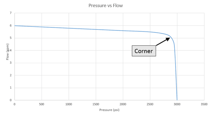
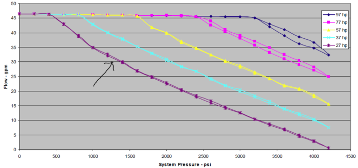
The chart above is typical of what we would see from both a fixed or variable displacement pump. A variable displacement pump with torque limiting would have a negative slope line where the torque limiter is engaged. (Below)

Pressure vs Flow Chart of a Variable Displacement Piston Pump with Torque Limiting

Equipment Needed

The first thing that you need is a flow meter test kit that has a flow meter, pressure gauge and needle valve. You can find these for as little as $500. You will also need some wrenches to take apart fittings, rags and oil pans. You are going to get oily! (Yea)

Testing Fixed Displacement Pumps

On a fixed displacement pump, we will be checking the pump and the main (system) relief valve at the same time. You should never run a pressure test on a fixed displacement pump without a relief valve installed. You can do serious damage to your equipment.

Testing Variable Displacement Pumps

Variable Displacement pumps are a little different. They all have an internal compensator and in most cases a remote compensator. Mobile equipment may also have load sensing.

For testing purposes, we will want to connect the load sense line to the pressure line and block any down stream functions. Also, set the remote compensator to the lowest pressure possible (usually all the way out). The remote compensator is almost always a simple cartridge style relief valve.

Test Procedure

  1. Disconnect all components / hoses from the pump discharge port except for the system relief valve on a fixed displacement pump.
  2. Connect the test flow meter to the discharge of the pump.
  3. Open the flow control valve all the way on the test meter.
  4. Start the motor or engine that powers the hydraulic pump.
  5. Check for leaks.
  6. Record the pressure and flow.
  7. Slowly shut the flow control valve which will increase the pressure.
  8. Record the pressure and flow values at roughly 500 psi increments.
  9. As you get close to system pressure, take more readings at smaller increments (maybe as little as 50 psi).
  10. Plot these values on a chart and compare to the charts above.

Interpreting the Results

If the tested values look like the charts above, your pump and relief valve work properly. Disconnect the flow test meter and reconnect the rest of the system. Your problem is located somewhere else in the system.

If your test does not look like the charts above, the pump can still be good. In both cases, there is a relief valve in the system. The variable displacement pump also has a compensator that can be causing issues.

Checking the Relief Valve

Most relief valves are cartridge style with two advantages; they are easy to remove to flush out contaminates and they are easy to replace.

Having your oil pan ready, unscrew the relief valve cartridge from the manifold (slowly). Once out, allow the hydraulic oil to clear out the manifold. Also inspect the cartridge for signs of contamination. If everything looks clean, reassemble and repeat the test.

Still Not Working?

If the test is still unsuccessful, replace the relief valve and repeat the test. If it still not producing pressure, replace the fixed displacement pump. It is bad.

With a variable displacement pump, we now need to isolate the problem to the pump or internal compensator. Thus far, we have avoided messing with the internal compensator because it is usually mounted on a pump submerged in hydraulic oil.

First we will eliminate the remote compensator completely as the problem by capping off the flow to it. Start the motor and look for rise in the system pressure. If it does not increase, we will shift our focus to the internal compensator. Reattach the remote compensator.

This is where things get messy if you have a submerged pump.

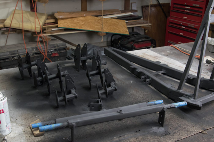
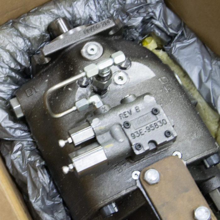
Locate the compensator on the pump which is the large block labeled “Rev B” on the photo below. Most times, you can clean out the compensator yourself. Find the assembly instructions or parts breakdown from the manufacturer if possible.

If not, disassemble one part at a time and keep good records. I usually take a picture each time I remove a part.

Disassembled compensator with components placed in order removed.

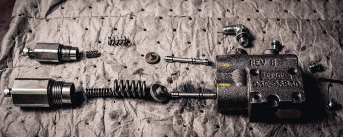
Look for contamination in the cavities and flush with hydraulic oil to remove loose debris. Do not use sharp tools to clean the components because scratches can prevent the components from performing correctly.

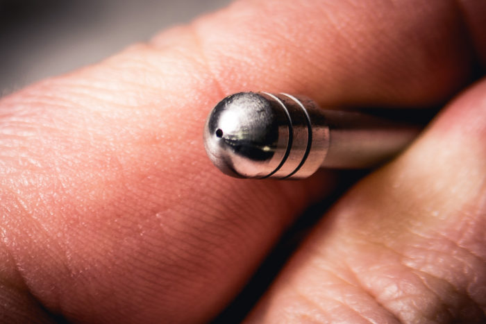
In the case above, there was a small amount of debris inside the small hole shown below. I gently pushed it loose with a small needle and blow it out with compressed air.

There was contamination blocking flow through this small hole. it was cleaned by using a small needle and compressed air.

Once the compensator components are clean, reassemble and install on the pump. Prime the pump according to the manufacturer’s recommendations.

Once primed, Reattach the remote compensator and run the test again. If the pump still does not produce pressure, your pump is bad and needs to be rebuilt or replaced.

What Causes a Pump to Fail?

Contamination and Over Pressurization

The main cause of pump failures is contamination. Debris that is in the tank or ingested from hydraulic cylinders can drastically shorten the life of a pump.

For variable displacement pumps, contamination seems to clog the compensator first. It has many small cavities that can get clogged easily. I recently worked on a piston pump where the shaft coupler to the motor shredded and parts of it were clogged in the compensator.

Over pressurizing the pump is the second most common reason pumps go bad. Make sure that your relief valve is installed properly and

‘Shelling Out’

‘Shelling out’ of a pump is a term used to describe a pump being run dry (without oil). Pumps are designed with very tight tolerances between moving parts. Common gaps are 0.0002 in (5 nm) and round surfaces are usually honed for accuracy.

The reason for this is that every gap will leak oil. The larger the gap, the more oil that is leaked. You can imagine that very small gaps are desireable for top perfromance.

The problem comes when a pump or motor are run dry. The gears in a gear pump are usually steel and the housing around it is some form of brass. If there isn’t any lubrication between the two, the brass will wear out quickly. Within seconds! As larger gaps are produced, you will never get full pressure out of the pump again.

How to We Prevent the Pump from Failing?

To prevent over pressurization and contamination, proper relief valves and filter are required. I recommend these two other articles for proper relief valves and oil filtering.

https://mentoredengineer.com/relief-valves-and-filters/
https://mentoredengineer.com/hydraulic-basics-4-components-every-system-needs/

Preventing Shelling

To prevent shelling out a pump, I recommend reading the manufacturer’s recommendation for priming a pump. For a submerged pump, this might be opening a case drain port on the top of the pump and let oil flow in. (You’re going to get slimy.) Other pumps may require pouring oil into the ports and case drain.

If your pump has shelled out, there is contamination all though out the system. If you have a high pressure filter installed, you’re okay. If not, you will need to flush the system at low pressure. The suction filter or return filter should prevent this contamination from being reintroduced into the system.

Conclusions

After reading this article, you should be able to diagnose a pump failure and know key places to look for pressure issues. You should also be able to prevent the common causes of pump failure.

Black Widow Backyard Roller Coaster Image Gallery

Cart Painting and Assembly

Lengthened Lift Hill 07/23/2020

The Track Loop is Complete!

6/29/2020 – There is still bracing and support that needs to be done but the loop is finished. We had a rail joining ceremony and later a “rose gold screw celebration” to fasten the last rail tie. Oh, by rose gold screw, I mean an ordinary deck screw that I painted metallic red.

Retracking of the Initial Drop to Increase Bank Angle

6/15/2020 As with all things, you look at the calculations and the numbers tell you something that isn’t logical. Well, the numbers were wrong and it took 3 days to rebuild the initial drop.

Photos of the Assembled Cart 6/25/2020

Posted 06/06/2020

Posted 05/18/2020

Why Tires Seem More Unbalanced at Certain Speeds

I used to drive a 2001 Saturn SL and as the car got up to 60 mph (95 kph) the tires were unbalanced and would shake the car. As I got up to 70 mph (113 kph) the car didn’t shake anymore.

All tires have a slight imbalance to them. The magnitude and location of the imbalance determines the tire’s natural frequency. When the tire is operated at or near the natural frequency the vibration increases dramatically.  Increasing or decreasing speed will eliminate the vibration.

Image by George Hodan

The car as a whole can be analyzed as a complex vibration problem. Items in the system that need to be considered are the imbalance and its location in the wheel, the rotation speed, the weight of the wheel and how the wheel attaches to the car via suspension.

Natural Frequency

When all this is known, we can calculate the natural frequency of the tire. The natural frequency is the speed at which the tire will naturally vibrate. The image below shows the natural vibration amplitude of a beam vibrating.

When the car operated at this frequency, the amplitude of the vibration to continually increase without bound.

The Linear Assumption

Mathematically this is correct but in actuality, there are many factors that will limit the vibration amplitude. To simplify calculations, we assume things like shocks, struts and springs have linear properties. For the most part, this is true. However, they are only linear in the intended operating range.

As the strut or shock reaches the end of the stroke, your linear assumption meets an abrupt increase. The same thing happens when a spring is fully collapsed.

There are lots of variables that come together so that even when I operate my Saturn at 60 mph, it doesn’t fall apart.

Finding the Natural Frequency

So, I’m not nerd enough to try to model out my car’s natural frequency. It probably would have taken me months to calculate all the variables.

No, I simply drove my car and found the vibration at 60 mph.

Beating

To be honest, it is near impossible to operate something at the natural frequency perfectly without complex controls. Often, we get a similar phenomenon when we operate near the natural frequency.

If system is being forced to rotate at a slightly different frequency than the natural frequency. The result is called beating. Beating is when the amplitudes will add together for some time and then cancel each other out a little later.

When stopped at a traffic light, I sometimes notice several cars in front of me with their blinkers on. The blinkers usually don’t flash at the same rate. For a brief period, they are in sync, but soon enough they are out of sync again. This is another example of beating.

Beating of a wheel with natural frequency speed of 60 mph being driven at 56.5 mph

In a car, the vibration will come and go over several seconds. In the case above, it will happen about every 6.5 seconds with the worst of it lasting for about 2.5 seconds.

Beating is not good for your tires or car. It will cause the tires to wear quickly as well as the suspension components. Prolonged beating may cause further damage to the car’s internal structure.

When I noticed the beating in my Saturn, I took it into the shop for a balancing. Too late, the beating already wore the tire through in one spot to the steel wire reinforcement.

Altering the Natural Frequency

Guitar strings will vibrate at their natural frequency. This frequency is changed by placing fingers on a fret.

Natural Frequency Is Outside of Operating Range

Depending on your system, you may have several natural frequencies to begin with. In an ideal world, we would want these frequencies to be outside of the normal operating range.

For a car, if you had a natural frequency at 100 mph, this might not ever be and issue because we don’t drive at or near that speed often. However, if you are a race car driver, this might be a speed that you are at quite often.

Balance the Tire

The main way to alter the natural frequency is to balance the tire. There are complex machines that do that quite accurately. These machines tell an operator exactly how much weight to add and where. Amazing.

In my early career, I worked on a project that pulverized railroad ties (about 800 hp). It was a large machine that had many teeth on a rotating head. When we started it up, it had a major vibration issue.

We ended up disassembling all the teeth and weighing them. At this point we rearranged the teeth so that the machine was more balanced than before. When we started it back up, the vibration was at an acceptable level.

Image courtesy of USAF

Don’t Run at That Speed

One final way to avoid the natural frequency is to quickly accelerate and decelerate through the natural frequency. My brother is a naval engineer and his senior project was to develop a hull and propulsion system for a new ship.

He mentioned that the ships propeller had two natural frequencies in the operational range. These frequencies were not at normal cruising speeds so they would add controls to not allow the propellers operated at certain speeds. The controls would quickly accelerate the propeller through each natural frequency. This minimized any damage that could be done to the ship.

In Summary

Tires seem to be more imbalanced at certain speeds because they are being operated at or near the natural frequency. This will cause damage to your tire, suspension and possibly the frame of your car. Change your speed so that you are not operating at that speed.

Go get your tires balanced….

6 Secrets for Synchronizing Cylinders

Corey describes several ways to have two or more cylinders move at the same time. This is not an easy task!

Transcript

Welcome to the Mentored Engineer. In this video I’m going to talk about timing hydraulic cylinders. There’s been several times that I’ve had to time hydraulic cylinders, and that means they extend and retract at the same rate with each other. There are problems with that because guess what? The world isn’t perfect.

You may have two perfectly identical cylinders coming from the same manufacturer, the same batch, and they’re going to perform just a little bit different each time. or you’re going to have different loads on each cylinder and you’re not going to be able to balance for that. So, if you have a schematic like this where you have flow coming into your directional control valve and you go ahead and extend it and this one’s really loaded and this one’s not loaded, the not loaded one is going to extend first, and once it gets to the end of the stroke, then this one will go, or if it builds up enough resistance, then it will go.

I once worked on a project where there was two cylinders pushing up a roof section of this device, and we noticed that they were cocking, and one of them was going up faster than the other. So, if I draw this from the side, we had a section here that had a pivot and then another section where the cylinder attached and then the other cylinder was further out here. You know, one would go and then the other would go and it would kind of do like this and every once in a while, get jammed. That’s a bad situation.

So, when you’re first starting to look at why do you have two cylinders, you want to mechanically tie those together as much as you can. All right. So, one thing is to think about first is can I stiffen up something to do this? And one of the things that we considered doing was having a giant tube here sage said that you know the tube really wouldn’t let it flex one side of the other so if one cylinder was going and the other one wasn’t able to push up the load this one would even out the load and they would be fighting each other a little bit but the pressure difference between one cylinder and the other would be very small because both of them were lifting the load you can’t always do that though

So right here, one of the ways that we can do this, probably one of the most ineffective ways is to have a motor type flow divider. So, if we go back to like a gear pump, we have two sets of meshing gears. Yeah, it’s a gear. In a cavity, and oil comes in these gears go opposite directions and then we will have one gear go out and another one go out so that as they spin it takes oil pushes it around half the oil goes out that way half the oil goes up that way and as the cylinder retracts both of them bring the oil back through there you can basically expect around 10 percent efficiency with that or as far as, you know, how well they’re timed.

So not really on, you know, the precise end here. They do have cartridge valves where they will they split and some of these are higher percentage, you know, higher, higher accuracy or higher precision flow divider and combiner. So, you can actually get a little bit better result with that. So, you know, a cartridge valve may be, you know, 10% or lower depending on the make and manufacturer of it. So, another way you can do this is by adding needle valves to our flow here.

Now you may already have a needle valve in your system and you don’t even know it yet for example if when you come to the split right here all right if the hose on this side is you know four feet and the hose on this side is 20 feet um you’ve already got a restriction in there even if it’s just the you know the force that it takes to move the oil through the hose more oil is going to go to this four foot section because it doesn’t have as much pressure drop it may just be you know if it’s 30 psi that could be a big enough difference between the two So one thing you can do is even out your hose lengths after the tee.

Even if you just have, you know, if you had to have 20 feet of coiled hose over here on this cylinder, even though you didn’t need it, it’s going to make a difference. Okay, so what you want to do here is add a needle valve in on each side. And that gives you, you know, a good delta P over each one. They’re going to try to be the same as much as possible. You’re isolating this half of the circuit from this half of the circuit.

It’ll make it better. So, you’re probably looking in the 5% error one to the other cylinders just because it’s not a fully compensated system. one thing that’s nice about this is it will allow re-timing at both ends so once you fully extend, they’ll both bottom out because there won’t be any pressure going here it’ll just be flying over here so another way to do this and it’s not very common is to have a double rotted cylinder so this is a cylinder with the rod sticking at both sides and it allows equal pressure.

Now, if you’re, you know, having an application where you’re pushing and that’s when you need your force, this is going to help you because it’s going to reduce your area by the size of the rod. But what you do here in this case is instead of teeing these both together, oops, that one, that one stays, you actually feed the extend port into the retract port of the other cylinder. So, oil will come out here, go into this one, extend it. That oil will now push this one out, and then that oil will return back to tank.

And it kind of works nicely. You’re going to lose a lot of force because this is return oil now working against this, so you’re going to have pressure intensification. So, your cylinders are going to have to be way oversized for your application to lift the loads you want because you don’t get the full pressure of each one. But they will be timed. They’ll probably be timed within 2%.

Another way to do this, also not done very much, is to have two drive systems. uh which would include two different motors two different directional control valves uh one controlling each one and you would just basically say like extend and you’re relying on your pump’s flow rate which also can get out of time Very expensive. Two motors, two directional control valves, and you’re not very much better than 2%. Alright, so the last one is the most accurate one and also the most expensive.

And that is to put some sort of position detection in your cylinder. So, there are several kinds. Some of them you can put in the base of the cylinder and it’s a sensor that measures how far the piston is away. You got LVDTs, which you can put in the cylinder. And there’s a sensor here that will tell how far the piston is away or how far the piston is along that line.

And it’ll send back LVDTs or what those are called. And basically, you got to feed that back in the control system. You have two directional control valves, one for each cylinder, and you can extend and retract those. Very, very precise. I mean, we’re talking down to less than a thousandth of an inch that you can get with that.

But you got to come up with the control system to do it. And you have all that componentry. So very expensive. But if you need it, it’s the way to go. I mean, you’re going to you’re talking about you know almost no error in those cylinders there’s one thing we need to talk about and that is re-timing we’ve kind of talked about it a little bit as you can imagine with this system there is oil that is going to sneak past the piston over time lots of time pistons are very sealed you know they’re not going to drift very often unless there’s an issue inside the cylinder

But eventually oil is going to go from one side to the other if it’s set up under pressure for a long time. And eventually these are going to get out of sync and there’s no way to re-sync them. When I say out of sync, I mean, you know, this one might be fully retracted and this one might still be extended an inch. You either have too much or too little oil in one of the cylinders. It’s because of how things work, especially since the pressure in this side of the cylinder will be different than the pressure in this side of the cylinder.

So, there’s going to be things that they just get un-synced and we want to be able to retie them. The gear pump is not something that can be re-synced. So, what we end up doing is we’ll put a small little needle valve here um so let’s just say this is eight gpm this maybe it’s going to be less than one or sorry that’s greater than one less than one gpm all right and that’s just a way to retime it where one gets to the end and then it forces the oil to go out through here to the other side

But we need to be thinking about that too. How do we re-sync these? How far off will they need to be before we need to re-sync them? Well, those are the most popular ways to synchronize cylinders. Just remember two things.

If you can find a mechanical solution for this first, do that. If not, make sure you have a way to re-sync these things so that if they get out of whack a little bit, they’re able to get back into order. All right, thank you for watching this episode of The Mentored Engineer and please subscribe to our channel. Thank you.

How to Select a Limit Switch – 9 Things to Consider

So there I was again; standing at a machine that I designed replacing a limit switch for the fourth time in a month. This time it would be different. This switch was used to detect the end position of a cart that rolled on rails. The limit switch had a lever with the roller on the end and was activated when a plate contacted roller.

The switch kept failing because the impact from contact was loosening the 2 screw pattern for the actuation head and eventually broke the plastic housing.

This time it was different because I was using a steel body design with 4 screws mounting the head. I haven’t serviced this switch in the nearly 2 years since. Small and seemingly un-noticable details in the switch can be the difference between years of service life.

Limit switches are an important component in almost every industrial machine. Here are a few basic pointers on selecting the right switch for your application.

Most engineers will pay attention to the body material, contact types and actuation method when selecting a limit switch. For the switch to last a long time, there must be considerations for the IP rating, wire sealing, and how the switch is mounted. Never allow water to pool against a seal.

Side Roller Limit Switch
Image by John R. Southern

On a recent application, I selected a limit switch where the head was only held on by two screws. This led to repeated structural failures in the switch from the cart that was rolling by it. The long term fix was to upgrade to a switch that had the head held on with 4 screws.

1. Cycle Limit

These are mechanical switches with moving parts. They will wear out. The cycle limit is usually given by the manufacturer in millions of cycles. This is usually the number of cycles to average failure.

Find out how many cycles per day, week or year your machine will plan to see and find out how long your machine is expected to last.

Many times, you will find that the switch will outlast the machine. If not, you will want to stay well below the average cycle failure. I suggest replacing these around 75% of the estimated life and always have a spare on hand.

2. Wire Exit

An IP67 rating on the switch is all lost if your wires are not sealed correctly. There are a few things that can help you be successful here.

  1. Electrical conduit is not water tight. If you need your switch to be IP rated, don’t run the conduit right into the switch. Have a short amount of ‘exposed’ wire, but protect it with spiral wrap, split loom, or a larger diameter conduit.
  2. Use a sealed strain relief. Yes, if you want to maintain your IP rating, you must use sealed strain reliefs for your wires. There are many kinds available; make sure the one you select is rated for the wire diameter and the IP rating desired.
  3. Select NPT strain reliefs. NPT (Pipe thread) is the most common form for strain relief in electrical devices. There are other’s types of connection out there and they can be pricey. NPT offers a wide selection of conductor size and number. If preventing water intrusion is a must, be sure to seal the threads with some Teflon tape or pipe dope.
  4. Add droop in wire. Unless your switch is mounted vertically with with the wires pointing down, adding droop to your wire is a must.
    1. If there is no droop, water will gather on the wires and run down to the strain relief. Over time, water pooling on the seal will eventually get inside. This happens even with potted electronics. Adding droop prevents water from pooling near the seal.
    2. Never mount your switch with the wires coming out vertically upwards!
  5. Don’t bend the wires too quickly – When designing your wire exit, make sure that you allow plenty of room for the wire to make any turns. If the wire turns too quickly, it can lay crooked in the strain relief and not seal properly. A distance of 8-10 times the wire diameter is adequate for most applications. Consider using an angled strain relief if this is a problem.
  6. Beware of Multi-conductor Wires. Multi-conductor wires are difficult to seal.
    1. On wires with a thin jacket, there may be bumps that prevent a good seal.
    2. There is space between the wires where water can collect. Even if both ends are properly sealed on the jacket, cuts in the jacket along the length can allow water to intrude into the switch by means of the space between conductors.
    1. The best way to ensure a good seal is strip the jacket back so that only the individual conductors enter the switch. Then protect the wires from damage.
Image by Glen Bledsoe

3. IP rating

An IP rating is a way to know how well an electrical device will stand up to its environment from water and other contaminates. It is not a rating of how well things like paint or other corrosion protection will hold up.

An IP number has two digits each number representing something. The first digit represents the ingress of solids into cavities. A rating of 0 is no protection and 6 will be “dust tight”.

The second number is the intrusion of liquids. The ratings for this digit go from 0 to 8. Zero is no protection from liquids. The tests get more intense as the numbers increase ending with 8 which no harmful water intrusion when immersed deeper than 1 meter.

Image by Dmitry G

Most switches we are concerned about will fall into the range of IP65 to IP67. Here are the tests:

  • IP65 – Water projected by a nozzle (6.3mm) against enclosure from any direction shall have no harmful effects.
  • IP66 – Water projected in powerful jets (12.5mm nozzle) against the enclosure from any direction shall have no harmful effects.
  • IP67 – Ingress of water in harmful quantity shall not be possible when the enclosure is immersed in water under defined conditions of pressure and time (up to 1 m of submersion).

For indoor applications, I recommend a minimum of IP65 unless the switch is protected from direct spray of water. For outdoor applications, I recommend an IP67 or higher switch. I would still add covers that will protect the switch from direct spray from a pressure washer.

4. Body Material

Plastic switch bodies are prevalent in the market. For your light to medium duty applications this may be adequate. Adding protection from contact and water intrusion will ensure that your switch lasts a long time.

Cross Roller Type Limit Switch
Image Courtesy of Automation Direct

Aluminum switch bodies are generally the my go to. They are robust enough to handle some misuse, but light and cost effective.

For your heavy duty applications, stainless steel is the way to go. Stainless steels are strong, weather resistant and have an excellent fatigue life. However, they will be more expensive.

Look for versions where the plunger is attached to the body with 4 screws rather than 2.

5. Contacts

Most switches come with a normally open (N.O.) and a normally closed (N.C.) set of contacts. Usually the two sets don’t use the same common wire. Some switches are available with 2 NO or 2 NC contact sets. If you need more, you can always run the signal through a relay with as many contact sets as you like.

“Fail Safe” Design

One thing to keep in mind when selecting a switch is safety when there is a failure. We always want our device to “fail safe.”

For example, if we have a rail system, but we never want the cart on it to go past a certain point we could install a switch at that point. If we wire the switch to be NO and give us a signal back when the cart is present the system will work fine.

However, if the wire has been cut, the switch will never send a signal and the cart will cruise on past the intended point. Not good!

Plunger Type Limit Switch
Image Courtesy of Grainger

However, with a simple change to use the normally closed signal, we will look for a high signal all the time to allow the cart to move all the time. When the cart reaches the switch, the signal will drop from high to low and signal the cart to stop.

Most importantly, if the wire is cut, the cart will think that it is at the stopping point and not move. This a fail safe! As a side benefit, the symptoms should prompt maintenance to look for cut wires and not faulty switches

6. Actuation

The super sweet thing about limit switches is that they come with a variety of actuators that can be used to sense almost any object or motion type. You should be able to find the perfect actuator for your application. Here are some of them:

  • Plungers- This is a linear pressing of the switch. You can buy these will various amounts of travel before and after the switch is activated. Some have rubber boots to protect the switch from ingesting dirt. These switches are intended to handle actuation in line with the plunger direction.
  • Ball plungers – Ball plungers can handle lateral motion very well. However they are very precise and don’t handle misalignment well. These are commonly used in valve systems to determine if a valve spool has shifted. Be sure to use these will lubricants in metal to metal applications.
  • Cross roller plungers – This version of a plunger has a roller mounted in it rather than a ball. They handle lateral motion very well and don’t need lubrication. As the roller diameter increases, the greater the misalignment can be.
  • Rod or Wand Actuation – These are great general purpose actuators and not for precision use. It is a long stem coming out of the switch. It works much like a breakaway torque wrench does; where it builds resistance and then snaps to indicate the switch has been made. They are robust and can sense objects in and direction perpendicular to the shaft.
  • Lever Action – These can come with or without a roller on them. Generally speaking they can be used as a plunger or a cross roller plunger. When used for lateral motion, they are good for single direction only. If ran the other way, the roller can catch and tear itself up.
  • Side Rotary Action – Probably the most configurable of all the actuators. They usually have a roller mounted on the end so that there are no scratches or visible marks left on the objects. Many of the levers are adjustable in length so that you can fine tune the contact point.
Lever Arm Actuator
SparkFun Electronics from Boulder, USA

7. Head Rotation

As already mentioned, the heads on the switches rotate and mount with screws. Only look at switches with 4 screws holding the head on. Switches with only 2 screws holding them together just aren’t strong enough for medium or heavy duty applications.

In addition to the four screws, look for switches that have tabs to further lock the head into position. The head is usually adjustable in 90° increments.

8. Mounting

On an aerial work platform that I designed, we had a “potted” PC board for controls. The way this was designed had a cover that I placed facing up. In rare situations, such as power washing, water would seep into the controls and sit on the potting.

This became an issue because the water just sat there for long periods of time; this eventually caused the board to fail.

The solution was to give water a way to exit by flipping the PCB over and drilling a small drain hole in the cover. The point here is that if water can pool on a seal, it will eventually get in.

Mounting a limit switch can be tricky. You need your mechanical action to work properly, but we also don’t want water intrusion into the switch at wire entry. To prevent this, you want the wires to enter from the bottom or side so the switch must be mounted horizontally or vertically with the actuation pointed up. If this is not the case, find a 90° strain relief for your switch or add a 90° street elbow.

Image by Bill Automata

You will also need to choose between tapped or through hole mounting. Many applications require using tapped holes because there is only adequate access from one side. One disadvantage is that you can cross thread or strip out the tapped hole on plastic bodies easily.

I prefer not to use this method simply because the screws needed are usually metric and I don’t have those stocked. So, it is an extra run to the store for me.

I prefer to use through hole mounting as a result. I stock equivalent sized screws and nuts. It does require another tool however.

9. Ratings

You definitely want to look for some ratings. First, most switches are UL listed. UL, Underwriters Laboratories is a non-profit group that evaluates electrical products for safety.

Second, you need to decide to select a NEMA vs IEC enclosure. International Electrotechnical Commission (IEC) enclosures are focused on lower cost and a smaller operating envelope.

NEMA enclosures are very durable and offer superior water and dust intrusion protection. Use NEMA rated enclosures for applications in harsh outdoor environments.

Conclusion

Choosing a limit switch can be a daunting task at first. I always feel lost because I don’t know what is and is not important. I hope this guide will help you get your feet wet in selecting your first switch. (Your feet may get wet, but the switch enclosure must stay dry.)