

This article is going to be a bit more technical than the previous article about fasteners, “The Magic of Fasteners.” I’m going to try to keep it as simple as I can, but this topic is so deep and complex. My intent is to give enough insight to make it practical, but not to cover every aspect or go into great depth.
Hydrogen embrittlement, stress corrosion cracking, mismatched hardware, fatigue and mechanical failure are the five ways that bolts and screws fail. Nearly all failures can be prevented by selecting the correct fastener and understanding the preload necessary.
We will be exploring the 5 ways that fasteners fail and spend the rest of the time trying to avoid it. Good bolted joints are possible to predict even before a single part is fabricated or a single strain gage is laid. However, my first rule of applying a fastener is this: if you can avoid using a structural fastener, do it! If you get nothing else out of this article, I will be satisfied. I don’t say this lightly either, because structural bolted joints are difficult to design, require expert insight and will generally take up a majority of your product support time. Designing a welded joint is much simpler and stronger. However, that is just not the world we live in, so here we go.
Six Reasons Bolts Break
1. Hydrogen Embrittlement
This is a very serious type of failure that can take place when a bolt breaks off and projects like a rocket due to the high load on it. This typically occurs within the first hour of the initial torqueing of the bolt. The reason this issue occurs can be linked to the electroplating process. As the water has a lot of hydrogen and oxygen in it, the electricity frees them up and they permeate the steel and start eating away at the material of the bolt. The result is in the weakening of the material and failure of the bolt head. Not good.
We definitely want to avoid this so we need to know the causes. All three of these need to be present for hydrogen embrittlement to occur.
- Susceptible material – High strength steel. Anything over a grade 8 fastener (and very rarely a grade 8)
- Stress above a threshold – There is no clear way to calculate this, unfortunately. Generally speaking a fastener designed to 50% proof will not be high enough. If it is an engineered fastener at 75% of proof of higher, this could lead to an issue.
- Hydrogen – From the electroplating. Consider a spin dip coating or mechanical plating instead.
- Initial flaw – Can be as simple as having the washer flipped upside down. Any small scratch or dent, even one imperceptible to the eye, could be the cause. Assume this is present in every case.
Although we want to entirely avoid this issue, the only positive element is that it typically occurs early in the assembly process before the product gets out into the field. In order to prevent hydrogen embrittlement, it is possible to bake all of the hydrogen out after the plating process is complete. This requires the fasteners to be heated to a certain temperature until all the hydrogen is burnt out of the part. Another way to avoid this is to have fasteners mechanically plated. This is a process where fasteners are turned in a drum (think concrete mixer) with zinc powder and the zinc is pressed into the fastener.
As a result of chronic hydrogen embrittlement issues, the United States passed the Fastener Act of 1990 that instated manufacturing practices and forced traceability of fasteners in an effort to protect the public.
2. Stress Corrosion Cracking
This type of failure occurs in a similar way as hydrogen embrittlement because the head will break off. The main difference in symptom is it can take place in the first 24 hours of torqueing and up to one or two months following. A good way to prevent this type of failure is to routinely do torque checks on the bolt. It is caused by an electrolyte which can be from how the bolt was manufactured or if it was exposed to certain chemicals.
- Susceptible material
- Stress above a threshold
- An electrolyte– From the electroplating, chemicals, just about anything.
Before we move on to the next failure mechanism, I want to issue this warning; if you need a high strength (stronger than grade 8) bolt for an application, something isn’t quite right with the design. Grade 8 fasteners are plenty strong, usually far stronger than the parent materials. You may need more fasteners or larger size fasteners in the joint. I say this because on the surface, switching to high strength fasteners makes sense, but you’ve now introduced a new potential problem of stress corrosion cracking and hydrogen embrittlement. These can have worse complications when a field population is considered.
3. Mismatched Hardware
This type typically manifest itself as a general failure when the proper hardware is not matched. To avoid this, make sure your bolt and nut grade are the same and that you are using a hardened washer if needed. If your design has the tendency to cave a washer, consider using a hardened washer or a custom thicker washer. Avoid washers that have burrs or sharp edges on them.
4. Fatigue
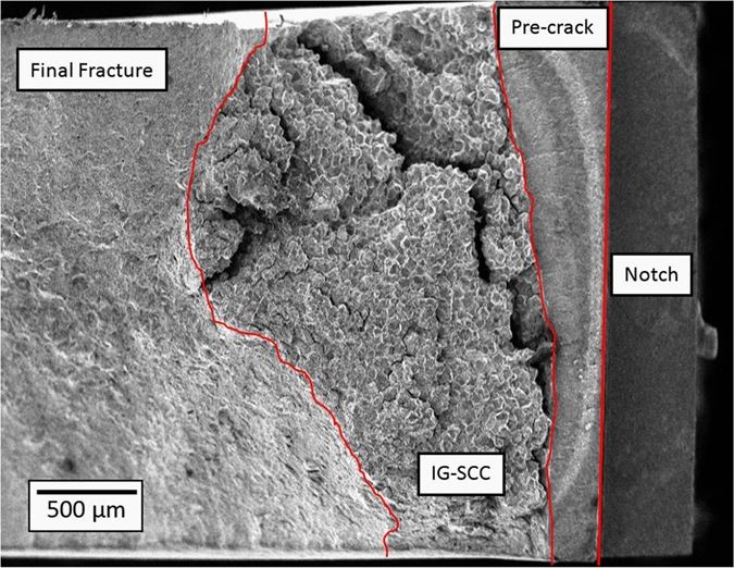
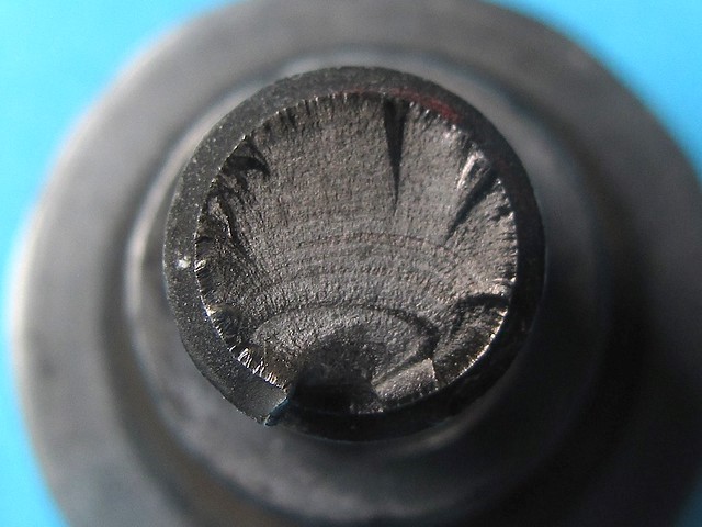
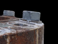
This type of failure occurs when the mechanical limits of the bolt are exceeded over time. The main causes of fatigue failure are higher stresses than expected or inadequate bolt pre-load. The higher stress may come from uneven loading of the fastener. If a moment load is applied, part of the bolt may relax while the other half is double loaded. If you examine a failure, you will see “velvety” portions of the break. This velvet surface is where the fatigue has been occurring. In the picture here, you can see that the fastener was firmly connected at the bottom. By analyzing the large sections of velvety texture, we can conclude that bottom stresses were pretty low. It is likely that this fastener had a moment load on it, which should be avoided.
Possible solutions for fatigue are:
- Use more bolts
- Redesign joints to eliminate moment loads on the fastener
- Consider the stress on the fastener from axial, shear and moment loads
- Determine if initial load on fastener is adequate.
Measuring the stress on a fastener is a complicated and tedious process, but on large project with critical fasteners it may prove essential. If actual data is not available, you can use calculated data to predict fatigue life. I would recommend calculating the theoretical maximum load than increase my preload and see where fatigue is no longer an issue. In order to calculate fatigue, I typically use the ASME Elliptical Equation, because it tends to fit empirical data better than the other, sometimes simpler models.
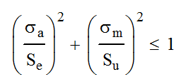
Where σa is the alternating stress [(σh-σl)/2], σm is the mean stress [(σh+σl)/2], Su is the ultimate strength of the material and Se is the endurance limit of the material. The endurance limit is generally half the ultimate strength, but there are corrections that need to be made for surface finish, temperature etc. We will not be discussing fatigue to this level in this article.
5. Mechanical Failure
This occurs when the bolt breaks right after the shank turns into the threads. It typically occurs due to the bolt being too small, high torque, or the joint not being designed correctly. Unless the bolt is strictly designed as a shear member, it should never break in the shank. We will spend the majority of this article addressing the prevention of this issue.
6. Corrosion
Well this just makes sense; if the bolt has rusted away, it won’t hold a load.
A bolt’s number one enemy is rust, since the overwhelming majority are made of steel. Most steel fasteners have some sort of coating on it which will turn white or gray, but the type of corrosion that we are concerned with is called ‘red rust.’ The method for evaluating the time to red rust is by using a salt spray chamber. In this chamber, a fine mist of salt is sprayed on parts continuously. Once red rust appears, the test is complete and the hours are logged.
Generally, exposure to chemicals or other substances that cause rust within 50 hours is not a good coating for outdoor applications. Once you are able to get around 100 hours without rust occurring, then you are getting some good use out of that bolt.
In the salt spray test, the white or gray is a lesser type of corrosion that doesn’t directly lead to failure. It is simply materials other than steel corroding first. This corrosion order is based on the galvanic chart.
Read this article for more information.
Preventing Mechanical Failures
There are a number of different ways that a mechanical failure will raise its ugly head. Here are the most common.
- Improper thread engagement
- Inadequate fastener stretching
- Primary load type is bending
- Misalignment of joint
- Preload too low – leads to fatigue
- Preload too high – leads to fastener stretching and loosening
Proper Thread Engagement
This is probably the most overlooked portion of fastener design. There are only two main principles to learn:
- Don’t engage the first three threads after the shank
- Make sure there are enough threads engagement into tapped holes.
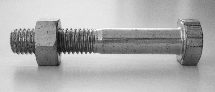
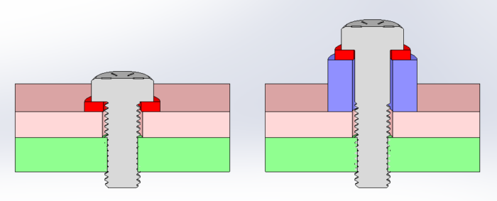
You should not engage the first three threads after the shank because it causes a stress concentration. In this image, you can see that the shank tapers off gently, but if the nut engaged on the first thread, the stress needs to make a sharp turn. If we wait until the third thread, this turn is much softer and the stress concentration is minimized.

If you are using a nut, you don’t need to worry about thread engagement as long as you are matching the bolt and nut grades. The problem comes inserting a screw into a tapped hole. Screws will have a threaded portion equal 2X the diameter plus 0.25”. The chart here indicates the required amount of thread engagement for a full strength joint. For steels this is usually easy to accomplish. For cast materials and aluminum, this is far more challenging. You will need 2X the diameter for engagement plus you will need to skip using the first 2 full threads. Since fasteners come in ¼ increments, there is not much, if any, wiggle room here. Common solutions are to change the design to use a nut, add a thicker washer to the head or make a counter-bore into the top material for a socket head capscrew.
Inadequate Fastener Stretching
This problem is the least common and often leaves engineers scratching their head wondering what is going on. I first encountered this on a piece of mobile equipment where a 3/8” and a ½” thick plate were bolted together. We used ½” screws tapped into the thicker plate to hold them together. (This was also a case of poor thread engagement as it was only mild steel.) We took the machine out for a drive and the screws loosened. These were general fasteners (50% of proof) so we changed them to an engineered fastener brought the torque up to 75%. They loosened up again. We brought the torque up to 90% and the same thing happened. We were all stumped. After doing some research, we found that this was not uncommon and the cause is that the fastener isn’t long enough to absorb small deflections in the joint. If you look at the governing equation, the one I think that all engineers have memorized but rarely use, you will see the answer.
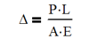
Where Δ is the deflection under load, P is the applied load, L is the length between the bottom of the head and the start of the fastener, A is the cross sectional area of the screw and E is Young’s modulus.
We cannot change P, A or E in most cases unless we add fasteners or change the size, so we need to change L. If we lengthen L, we increase the minute deflections allowable under the given preload.
Primary Loading is Bending
Fasteners are not designed for bending loads. A fastener has a relatively small diameter in comparison to what is being joined. It is foolishness to design a fastener to take a bending load, but all so often bolts fail in this fashion. A telltale sign of this type of failure is seeing a large asymmetrical velvet section on the break.
The strength of a fastener comes from its area and not the area moment of inertia. As an engineer make your joints a combination of axial and shear loads. The formulas for calculating he stress are as follows:
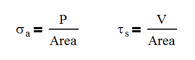
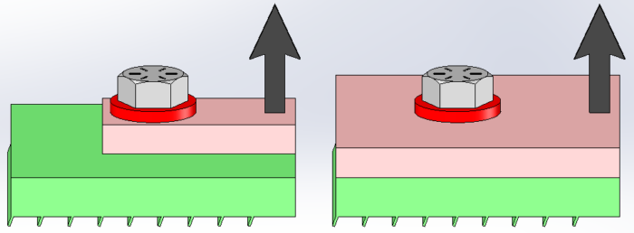
Yes, both are a function on the area! This is how we get maximum strength from the fastener. So let’s look at a classic example of a screw subject to bending loads. Quite simply, the figure on the left shows an upward force on the right side and the top material barely larger than the washer. This load will pry the parts apart and cause a slight slope to develop under the head of the screw. The slope with unevenly load the screw causing it to have higher tensile load on the side closet to the load, aka bending. To avoid this, change load on the fastener from a moment to one part of a couple. In the figure on the right, there is much more space on the opposite side of the load. The more space allowed, the more like a couple it is. The couple manifests itself as a compression load at point ‘A’ and a tension load at the bolt centerline. There are no hard and fast guidelines as to the proportions, but the further they are apart, and the closer the fastener is to the load, the better.
One thing to consider is the thickness of each part. If the top plate is too thin, it will deflect too much and you basically end up with the case on the left anyway.
Misalignment in the Joint
It almost goes without saying that a fastener will fail prematurely if it is installed incorrectly. If the screw’s shaft isn’t visually perpendicular to the hole, it doesn’t have a good chance of being successful. There are usually several obvious causes to this:
- The washer is hitting on a bend or weld
- The components don’t align properly
- The fastened components are initially to far apart
Try to solve these problems first. If you have multiple fasteners in a joint, try to have both plates CNC cut (laser, plasma) so that they will lineup every time. If you are mating several surfaces in a joint, can these surfaces be held better in a welding process? Perhaps the entire joint needs to be machined after welding.
I will give you one glimmer of hope. This type of thing is already accounted for in testing standards. ASTM F606, a standard that governs fastener testing, requires a “wedge” test. If you imagine doing a standard tension test on a fastener, you would expect the bolt and nut to be on surfaces parallel to each other. This wedge test requires an angle to be put on the side of the part to be tested. These plates are not parallel anymore and the bolt will now have a bending component. The standard requires different angles based on the diameter of the screw. This should give you some relief that your fastening systems don’t have to be perfectly perpendicular to be successful.
Preload Too High – Leads to Yielding, Preload Too Low – Leads to Fatigue
This is where most failures occur. Since the analysis for both are the same, we will tackle them together. For general fasteners, those that aren’t a critical structural element, we like to stay below 50 percent of the proof strength. Examples of this are bolts that hold on covers, valves or other items that won’t damage the user or machine. In design, I like to be a little more conservative and look for a 5:1 design factor from hand calculations. This usually keeps me farther away from low preload issues without causing excessively larger or a high number of fasteners needed. Most bolts fall into this category.
The remaining fasteners fall into the, engineered fasteners category. An example of this is a rotation bearing with a crane or the gearbox that causes it to rotate. For fasteners like these, it would be best suited to aim no higher than 75 percent of the rated proof load. The reasoning behind this is that we do not want to go too low which forces us to use a larger bolts or higher grades. Also, we do not want to have a situation where the bolt is overloaded and be at a disadvantage due to stretching the bolt which in turn creates a propensity for it to loosen. If and when this occurs, it can cause another bolt near it to pick up the extra load. This is generally undesirable.
Fastener Tensile Area
With fasteners, the tensile area is not equal to the area of the minor diameter. No matter where you take a section, you will find that the cross section will contain some thread and that area should be counted in your calculation. For example a ½” screw has a minor diameter of 0.4056 in leading to an area of 0.1292 in^2. However, when the thread is included, an area of 0.1419 in^2 is the tensile area. This is 9.8% more usable area.
Torque and Preload
The other thing to consider is that we are applying torque to a bolt and not directly applying a tensile load. This introduces data spread into our system that needs to be accounted for. Unfortunately, we need to introduce statistics into our calculations. Yeah, I don’t like it either, but we will keep it simple. But this spread is the main reason why we want to design to 75% of proof: some screws may be at 60% while others are at 95%. As long as we don’t get to 100%, the bolt won’t stretch and we will be good.
So torque and preload are related luckily by the following formula.
T = (K D P)/12
- T = Torque (ft-lbs.)
- D = Nominal Diameter (inches)
- P = Desired Clamp Load Tension (lbs.)
- K = Torque Coefficient (dimensionless)
- The 12 is a conversion between inches and feet.
The value of K is the most difficult to estimate making a very simple equation complex. The general range is 0.10 for lubricated fasteners to 0.25 for rusted or hot dipped galvanized. Our goal is to make this constant very low and consistent. Good values for this are 0.12 to 0.15. The main way to accomplish both is with lubrication. Lubrication comes in a variety of forms
- Dry film lubrication
- Oil lubrication
- Copper anti-seize
- In a pinch, you can eat some Doritos or pizza and wipe your fingers on the bolts. It doesn’t take much, but it makes a big difference.
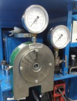
Bolt Tension Tester (above), Torque wrench calibrator (below)
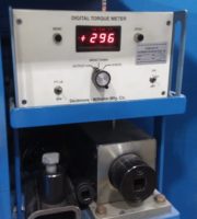
For example, we can take a 0.50” bolt and torque it to 64 ft-lb. When a k-factor of 0.13 is used, we should expect a preload of 11,815 lb. As we can imagine, the torque applied isn’t the same on every bolt and neither is the k-factor. To get good results, the first thing we need to do is make sure that every torque wrench is properly calibrated and has a set inspection schedule. Second, we need a sample of torqued bolts and their preload. To do this we will need a bolt tension tester. A screw and nut are coupled in the center hole and as they are tightened, a gauge will read the load on the fastener. Here are a couple notes:
- It is important to use the exact screw, lubrication and nut only once. Yes it seems wasteful, but this is an application where human souls may be at risk. A second or third use of the components will lead to different results.
- If the screw goes into a tapped hole, a sample of the tapped hole in the same material needs to be used.
- You may have to use longer or shorter fasteners to keep the same thread engagement.
- Finally, be sure to torque from the same side as is done at assembly. Don’t tighten from the head in testing but assemble by tightening the nut. You get different answers.
Statistics of Bolt Torque
So on to the long awaited statistics part of this. (See how I brought it up long before we got to it so that your blood pressure would lower.) The first thing that needs to be done is select a sample size. I recommend somewhere between 8 and 15 samples. I have made up data for 20 tests of a ½” fastener when torqued to 64 ft-lb. The first 10 samples are directly from the factory and have no additional lubrication added. Please note that this is an essentially uncontrolled lot and depending on the length of time and location it was stored could give us dramatically different information lot to lot. The second group of samples, also torqued to 64 ft-lb, had copper anti-seize applied to the threads before install.
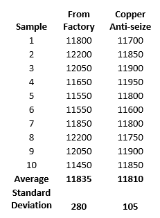
You can see that both samples average out to about the same amount, giving a k-factor in both groups of 0.13. But one group is clearly better than the other. The fasteners with copper anti-seize have a smaller range of data scatter and we see this from the standard deviation. If you remember the bell curve from your statistics class, you may recall that at one standard deviation, 68% of the samples will fall within that range. At two, it is 95% and at 3 it is 99.7%. (It’s ok if you didn’t remember, I remembered for you). So at 99.7% that is pretty close to 100%, we should use that as the base of our calculations.
So with the factory sample set, 99.7% of our fasteners should have a preload of 10995 lb. (77484 psi, 59 ft-lb) and 12675 lb. (89323 psi, 69 ft-lb). Good if you are using a grade 8, but overloaded if you are using a grade 5.
With the copper anti-seize sample set, 99.7% of our fasteners should have a preload of 11495 lb. (81007 psi, 62 ft-lb) and 12125 lb. (85447 psi, 66 ft-lb). This is a much more controlled data scatter, but still a little overloaded if you are using a grade 5. You might back off the torque a little, change to a larger fastener or switch to grade 8.
Statistics complete! Breathe now….
Verification of Critical Joints
Depending on how critical your joint is, you may want to back it up with testing data. I recommend running a strain gauge test on the fasteners. It is difficult, but on larger bolts you can put strain gauges on bolts. There are two methods, but the more common one is drilling a hole in the bolt through head and centered on the shank and putting a specialized strain gauge in the hole. You will need to correlate the strain reading with the torque using a bolt tension tester before install.
From our statistical analysis above, you will want to read data from both under-torqued and over-torqued fasteners. The under-torqued fastener may be subject to fatigue loading in testing and an over-torqued may yield and loose preload. In either case, you will want to know what is happening and how to minimize the effects.
Finally, having real data on a fastener will allow you to perform fatigue analysis on the fastener. If there are multiple fasteners in your bolt pattern, you can then find out which one is the highest loaded. At that point, you can change the design to lessen or better distribute the load. You can also loosen or remove that bolt and run the test again. This will demonstrate what effect a loose fastener will have your our system.
Conclusion
Yes, bolts are still magic and we need to understand how they fail so that we can prevent failures in our designs. Knowing how to diagnose the five failure modes of fasteners is a valuable tool in and of itself. Being able to accurately predict bolt behavior, by calculations and statistical analysis, might just impress your manager. We all use fasteners in some way shape or form, so you need to know how to apply them properly.