

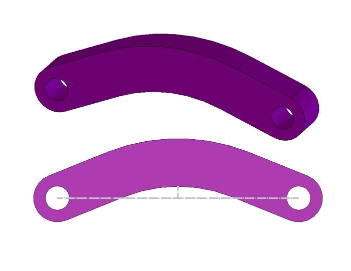
Curved beams are sometimes a necessary evil. Whether it is a link of chain or a banana link, they don’t calculate stresses the same as a straight link. After recently designing a banana link, I wanted to share with you the process of calculating the bending and axial stress in this unique situation.
Mechanical stress on a curved beam is unique because the neutral axis is not located at the centroid. In order to calculate the stress, you need to determine the highest loaded point, calculate the centroid and neutral axis. Finally, evaluate the inner and outer stress and add in axial loads.
Let’s talk briefly about curved beams and how they differ from just a straight link. In a straight link, the stresses will evenly distribute themselves throughout the cross section. This makes great use of all the material.
Curved beams however function much differently. If you take your drone up and look at a river, you will probably see some oxbows where the river will wind back on itself. Naturally, you will find the water moves quicker on the inside bank and much slower on the outside bank. Likewise, stress tends to pile up on the inside and less on the outside of the curved link.
Sharp Corners
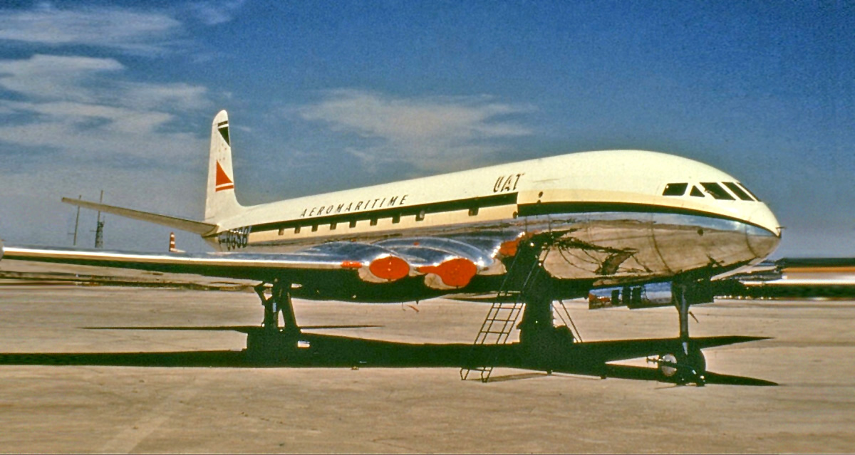
Because of the curvature higher stress is going to be piled up on the inside surface so you will need to first be aware of unwanted stress concentrations due to sharp corners. Always use a radius where possible to minimize this effect. One tragic example of this is the British airplane the Comet made by Havilland. This plane was the first jet airliner and it suffered multiple catestrophic failures. After investigations, the culprit was that the windows were made with square corners and the planes came apart in the air from fatigue loads. So please add radii in all corners.
In fatigue, a general rule of thumb is if it looks like a crack it’s going to act like a crack. If you have a sharp corner and you know you’re passing a lot of load through, it will act like a crack! Don’t start the crack! Give it a nice round radius.
If it looks like a crack it’s going to act like a crack.
Built Up Shapes
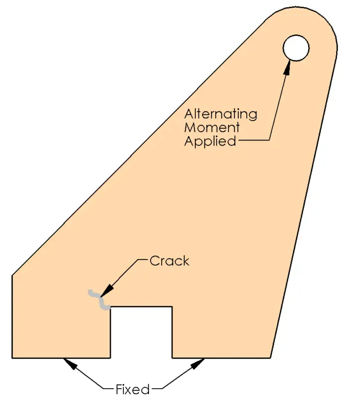
Your curved beam may be hidden. A number of years ago, I was designing a plate that was bending about the strong axis. It had a large cutout in it. When the moment went negative, there was a large tensile stress on the left hand side. Unfortunately, this section had a sharp corner and failed (luckily) in testing. After doing some curved beam analysis, we increased the radius and shifted the cutout in it. Problem Solved, but beware; your curved beam may be hiding.
Stress Analysis of a Curved Beam
Where to Calculate
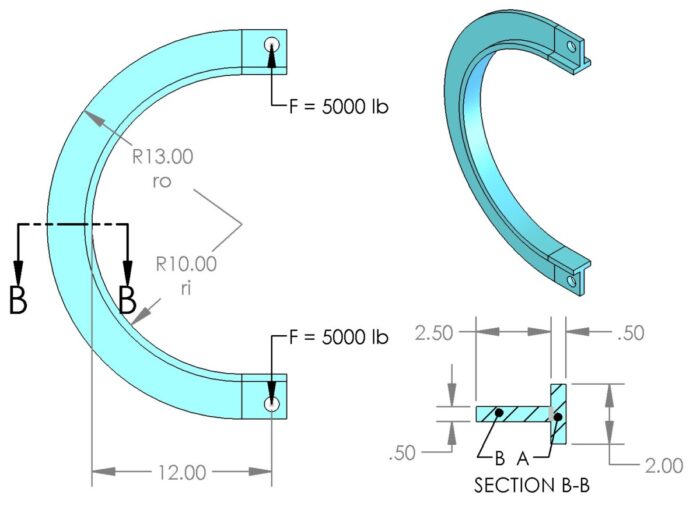
The first question most engineers face is where to calculate the stress. Sometimes it is obvious like with a banana link or a chain. Since the link is a two-forced member, any load will rotate the part until it is in line with the load. We can simply draw a line between the load points and find the furthest offset distance. In the beam shown below, it happens to be in the center. (Note that in beams with small offsets the line of action may still be on parent material. This is still a curved beam.)
If you have a case where the load is mostly axial, but the structure can support moments, you will have to use some engineering judgement. Generally, I will shoot for the centroid of the section at each end and then draw my line. I may even bias it a little to make it a worse case scenario.
Layout and Terminology
What makes curved beams tricky is that the neutral axis is not at the centroid like it is in a normal beam. We will call the radius at the neutral axis rn and differentiate it from the radius at the centroid, rg. In all cases, the neutral axis will be less than the radius at the centroid.
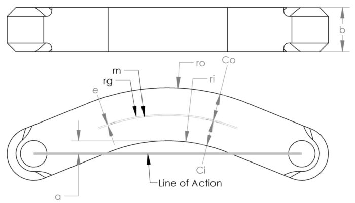
| Symbol | Description |
| A | Cross sectional area |
| ri | Inner radius |
| ro | Outer radius |
| rg | Radius at centroid |
| rn | Radius at Neutral Axis |
| ci | Distance from inner radius to neutral axis (rn-ri) |
| co | Distance from outer radius to neutral axis (ro-rn) |
| e | Shift in neutral axis (rg-rn) |
| d | Distance from line of force to neutral axis |
| b | Section width |
Calculating Neutral Axis, Centroid, Moment and Stress
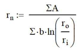
The first thing that we need to calculate is the neutral axis, which is done with the following equation. In our example, we only have one component so we can ignore the summations. (Σ symbol). As a result, we get the 10.43in neutral axis.
The centroid in this section is simple since it is a rectangle. It is the average of ro and ri or 10.5 in.
Now that we have the neutral axis and centroid, we can easily calculate ci, co, e and d. Hey, we’re half way done already.
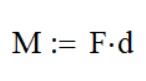
The moment is next. It is simply the force applied multiplied by d.
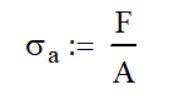
Finally, we will calculate the stresses. If your application is from an applied load, you will need to calculate the axial stres as you would in a straight beam.
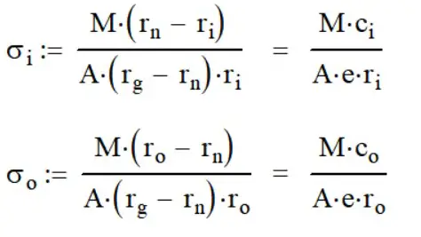
Moving on, we can calculate the inner and outer stresses using the following formulas. There are two ways to approach this depending on which variables you want to use.
At this point, you will need to add your axial stress to the inner stress and subtract it from the outer stress. We are done! But wait, there’s more.
Calculating Built Up Sections
If you have noticed, 90% of the problem is determining what rn and rg are. Once that is complete, the rest is easy. In a rectangle, it is easy; other shapes are more difficult. Let’s do some analysis on this T-section. (Note: all dimensions are in inches)
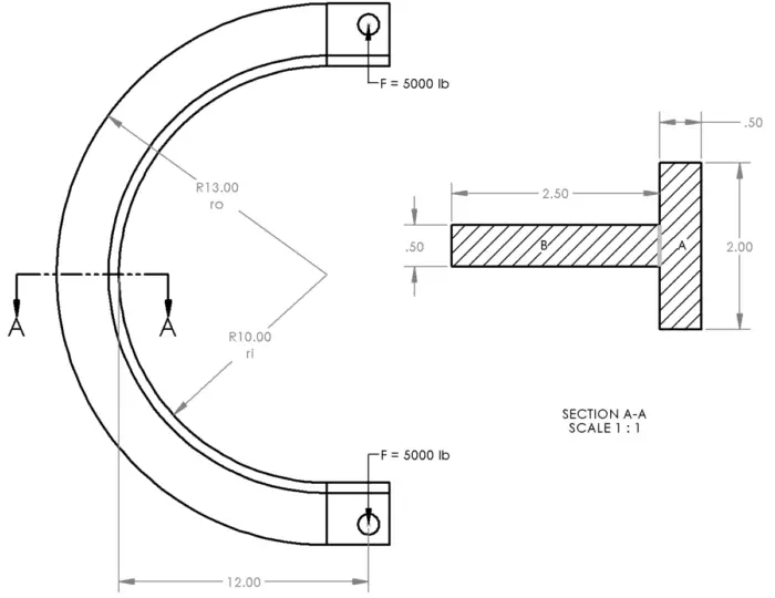
The trick here is to break our section down into smaller, easier chunks and look at those individually. Here we can easily divide it into sections A and B shown above (Right image).
Centroid and rg
The Centroid is the sum of the areas times the distance from point to the center of that section divided by the total area. Ouch, let’s break this down.
We have rectangles A and B. Let’s put our point at the inner radius, ri. The centroid can be calculated as
(0.50 * 2.00 * 0.50 / 2 + 2.50 * 0.50 * (2.50 / 2 + 0.50)) / (0.50 * 2.00 + 0.50 * 2.50) = 1.083 in
In order to convert this to rg, we need to add rg to ri. 1.083+10 in = 11.083 in.
Neutral Axis
The numerator (top) here will be the sum of the areas which is what we just calculated in the denominator of the centroid calculation.
0.50 * 2.00 + 0.50 * 2.50 = 2.25 sq in
The denominator (bottom, also not the ride at King’s Dominion) is a wee bit trickier. The variable b is the width of each section, so 2.00 for Section A and 0.50 for Section B. The variables ro and ri will change for each section. In Section A, ri is 10.00 in and ro is 10.50 in. In Section B, ri is 10.50 in and ro is 13.00 in.
The denominator is then:
2.00 * ln (10.50 / 10.00) + 0.50 * ln (13.00 / 10.50) = .0976 +.1068 = .2044 in
And rn is equal to 11.01 in
Common Mistakes
The first common mistake is using log (or log base 10) instead of the natural log (ln). I did this when writing this article. Luckily, the number will be so out of bounds it is easy to spot.
Second, when calculating the neutral axis for a section that is composed of multiple sections, you can use the summation wrong. These are individual sums of the numerator and denominator and not sums of the whole equation. If you’re not being careful you will end up with a number that’s completely wrong.
So on the numerator, add up all the areas. If you are using a cool program like Solidworks, you can have it calculate it for you. On the denominator, sum up all the widths with the log. Only then will you divide the numerator by the denominator.
Calculating the Stress
We’re in the home stretch! Since our beam is a two forced member, we will have an axial load
The axial stress is 5000 lb / 2.25 sq in or 2222 psi.
The moment is the force multiplied by d which is the distance from the load to rn. We have the distance to ri given, now we will subtract ri and add rn.
M = 5000 lb * (12.00 – 10.00 + 11.01) = 5000 lb * 13.01 in = 65,050 in-lb
Next, calculate the inner and outer stresses with these formulas
Inner stress = 65,050 (11.01 – 10.00) / (2.25 * (11.083 – 11.01) * 10.00) = 39,999 psi
Outer Stress = 65,050 (13.00-11.01) / (2.25 * (11.083 – 11.01) * 13.00) = 60,624 psi
Finally, we will add the axial stress to the inside and subtract it from the outside. Our inside and outside stress are respectively 42,221 psi and 62,846 psi. Please note that it is always important to calculate both the inner and outer stresses on non-symmetrical shapes. This shape shows that the stress is significantly higher on the outside and perhaps the web needs to be lengthened to lower this stress.
Selecting an Ideal Section
To save you some time, I want to show you which sections are better at this than others. Let’s start off with a round bar.
Round Bar – No
Round bar is a terrible choice for curved beams. We know that rg will go through the center, which means that rn will be closer to the inside radius. We’re at a a pretty bad disadvantage already because that small distance really increases the stress on the inside. If you didn’t notice, most of the material in this shape is in the middle where if does nothing. Not very efficient; let’s look at something that takes advantage of the neutral axis shift
Rectangular Bar – A Better Alternative
The next common shape is a rectangle and you will want to try to use it with the short edge closest to the load. A benefit of this shape is that if you double the long side you’re essentially quadrupling your load carrying capacity. So having a deeper section, rather than a wider section, is far better.
I-Beams – Now We’re Talking
I beams make the most out of the inner and outer material. So it will be a great shape for a curved beam.
However, I recommend against this because it’s hard to make. You can’t form a one piece I-beam into a curve unless it is an unusually large radius. You’ll probably end up cracking the section or need really large equipment to handle the forming process.
For a curved I-beam, I recommend that you make the beam out of 3 flat plates. You can roll the inner and outer plates and use the web to hold the proper shape. The downside is that you will need to weld the beam continuous to prevent fatigue cracking. Stopping will create an unwanted stress concentration.
T – Sections
T-Sections like the one we just calculated are easy to form and make good use of the material. The way we showed it is with a rolled piece at the end is ideal.
However, if you don’t have access to a roll form machine, there is another option; you can sandwich the web between other flat cut parts. This way you can build up a section giving you an ideal beam.
The downside is the inside edge. In a perfect world, you want all the material at the inside edge to be on the inside radius. If you want to weld the inside of the plates, like the below left image, you probably want to recess the web plate (further than the inside radius) in order to get a fillet weld. This causes you to lose some “free” stress reduction.
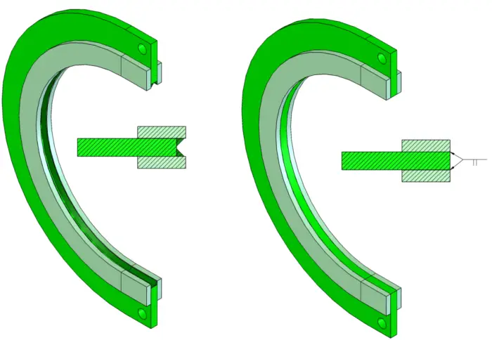
Another option is to put all three plates together (shown above right) at the inner radius and add a square (butt) weld on the seams, not as a structural weld, but in order to keep the plates from rusting.
Trapezoid
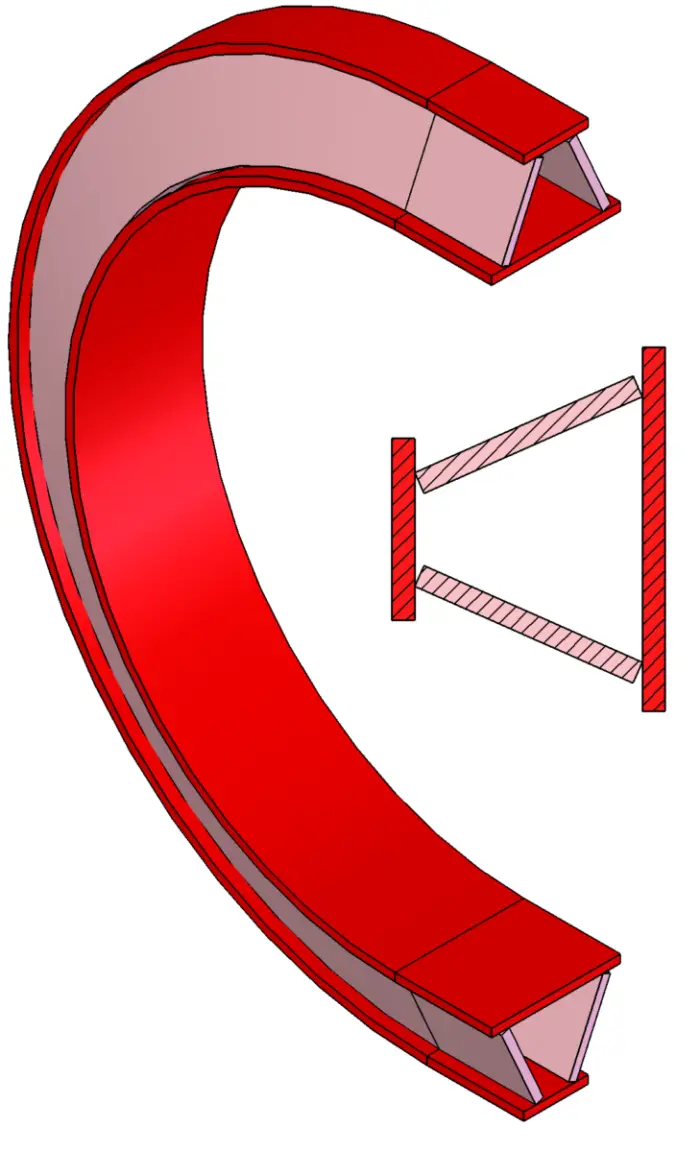
There’s one other section that I haven’t found an application for but I think it’s pretty cool so I’ll just share it with you: a trapezoidal section. I would make this section out of 4 plates using a roll form machine for the inner and outer plates. The 4 plates also let’s you tune in exactly what your shape should look like for you application.
A trapezoid has all the benefits of an I-beam, but it will do significantly better with torsional stress, because it is a boxed in section. If you are at all worried about inelastic buckling, this is your section.
Summary
Curved beams are everywhere (possibly hiding) and need special attention because they don’t follow traditional bending calculations. The most difficult issue with these beams is determining the neutral axis because it differs from the centroid of the section.
Finally, choosing the right shape for your beam is important. Stay away from round bar and lean towards T-shapes and I-beams.