

So I really have no one to blame for this but myself; I am 100% responsible. However, a special thanks to Dr. Tommie Thompson for making me never forget what a Section Modulus is. (Yeah, I still blame him)…..
Let me back up. I was a junior in college about to take the third of four tests in my Strength of Materials class. We had just discussed bending and transverse shear stress. I walked into the test fully confident on the material and ready to ACE this test.
These tests were only 4 questions each, taking about 12 minutes. Not knowing one question would drop me from an A to a C. Ouch, and BTW, I didn’t do so well on the first test.
Things were going very good until Question 3, “Determine the Section Modulus of these two I-Beams stacked on each other.”
Section Modulus? What is that? Was it mentioned In class? Was I daydreaming again? CRAP!
Well, I did what I could. I got the individual beam’s area moment of inertia and used the parallel axis theorem to move the so they could be stacked. I also figured out the distance from the centroid to the outer fiber, c.
But what was this Section Modulus? I moved on to the next question…
After the test, me and some of the other guys in the class talked and they didn’t know what it was either. Except of one guy (crap, any curve was now shot). He mentioned that there was two short sentences on it in the book, but Dr. Thompson never mentioned it in class.
I received the test back with a score of 85%, not bad, but I knew this material. I literally had all of the components for the answer, I just didn’t divide I/c.
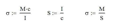
The Section Modulus is a geometric property of a shape that quickly indicates the overall strength when bending loads are applied. It is the ratio of the Area Moment of Inertia divided by the distance from the centroid to the outer fiber (S= I / c). The larger the section modulus, the stronger the section.
Why Use the Section Modulus
The section modulus, usually denoted by a capital S (sometimes Z for the old folks), is equal to the ratio of I/c in the classic equation
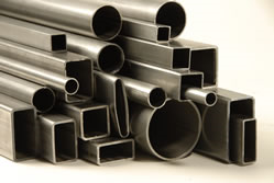
The main purpose of the section modulus is to easily compare the strength of different shapes and sizes. It is also beneficial in comparing size with thickness in tubing picking the optimal shape for your design without much calculation.
As an example, let’s say I have a cantilevered beam and I know my load and yield strength. I calculate that my required section modulus needs to be 5 in^3. I can begin to look into section tables (like the Load & Resistance and Factor Design) and find the section modulus I need. I see that a 4 x 4 x 3/8″ tube would would work, but that is very heavy. I then see that a 5 x 5 x 3/16 tube would also work and it is half of the wall thickness and 30% lighter. Nailed It!
Since I’m thorough, I skip a few pages and that a C6x13 channel or a W6x9 would be plenty strong. If I was deciding only by weight, the I beam is the clear winner at 9 lb per foot. I did all this in less than 5 minutes.
Over time, this number will help you to size how big sections need to be in your head. From experience, I knew that a section modulus of 5 in^3 was about a 5″ square tube.
Another benefit of using the section modulus is being able to see if jumping to a higher grade material is worthwhile. A company I used to work for had a 12 x 12 x 1/4 tube made of 50 ksi steel. Manufacturing wanted to change the design to a fabricated tube made of 3/16 thick 80 ksi plate.
In order to justify this, manufacturing had done the simple calculation below to compare the two materials using the material strength and the section modulus. We can easily calculate the maximum moment the section is capable of handling. Using the 1/4 wall tube as a baseline, we can then compare the 3/16″ wall tube and see that it has a higher moment capacity.
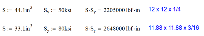
This was great analysis on the part of our manufacturing department and would be a tremendous weight savings as well. While this change was viable from this perspective, going with a thin wall tube (or plate) is not always a good idea. In this case, there was a major compressive load on one side of the tube and the plate would buckle because it was too thin at 3/16″ wall.
Section Modulus for Common Shapes
Luckily, the section modulus for many common structural shapes is easily calculable. The table below shows common shapes. With a little work, you can determine the shape and size you need for your design.
| Shape | Figure | Equation |
|---|---|---|
| Rectangle | 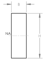 | 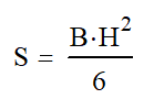 |
| Rectangular Tube | 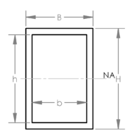 | 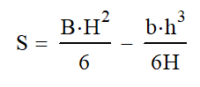 |
| Circle | 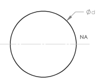 | 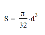 |
| Round Tube | 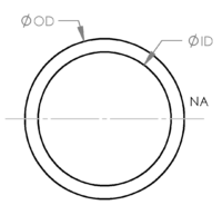 | 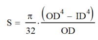 |
| I Beam | 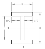 | 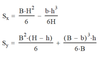 |
| Channel | 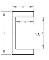 | 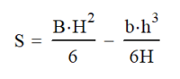 |
| Diamond | 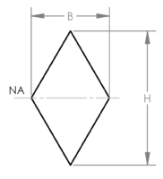 | 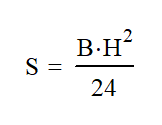 |
Preferred Section Shapes
In order to optimize your section (usually this is with respect to weight), you will want to pick a shape with the majority of the material at the outer fiber of the shape. Tubing, whether rectangular or round, is best with I-beams in a close second place. Tee shapes or angles are not good choices.
With tubing, all of the material is at the outer fiber. You have chosen wisely. I prefer to use round tube for members in torsion and rectangular tubing for beams in bending. The flat parts of the tube allow a greater portion of the section to be at the highest stress thus optimizing the use of material.

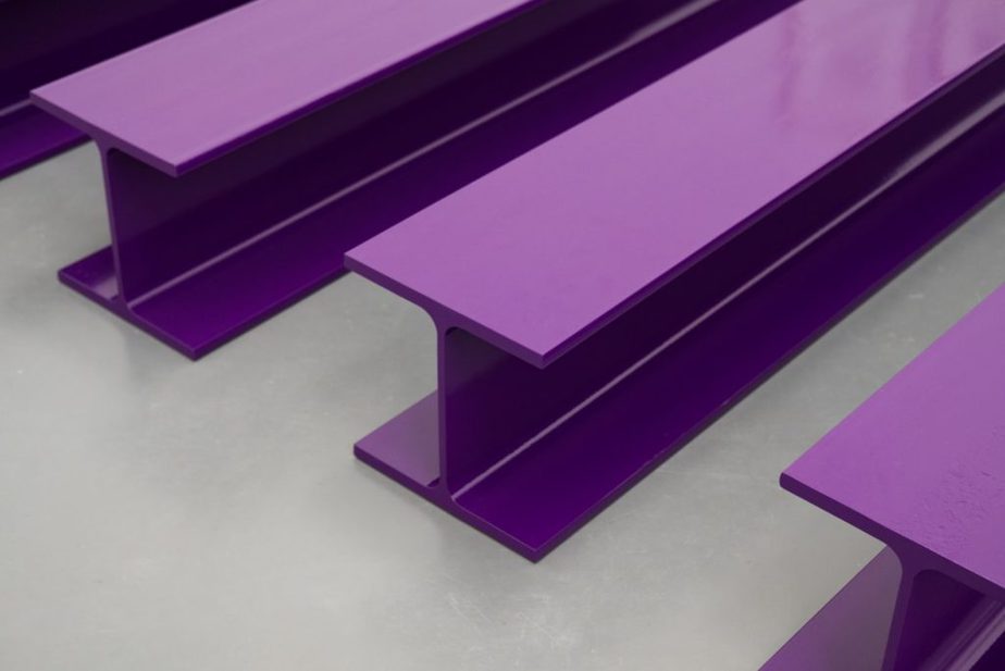
I-beams are next up because they offer maximum strength in one direction and minimize the thickness of the web. This leads to lower weight per foot. These are perfect if you have a load that can only act in one direction. This is why you see I-beams on trailer frames and bridge design. However, they offer very little resistance when a load is applied along the weak axis because there is very little material at the outer fiber.
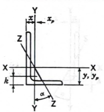
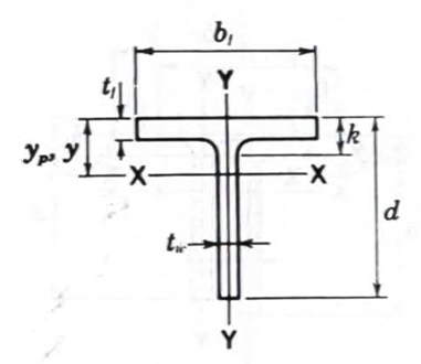
Angle and Tee sections are poor choices in structural design because there is very little material at the outer fiber. Looking at the drawings below, when going from the centroid (X or Y line) to the outer fiber, the maximum distance is always to the end of the leg where there is very little material. That makes these sections poor choices. Furthermore, these sections tend to buckle and deform easier than all other sections.
Stiffness vs Strength
When designing your beam, you need to consider both stiffness and strength. While they are similar, they are not the same. As we have already discussed, strength is a function of the section modulus which is a function of both the area moment of inertia and the distance from the centroid to the outer fiber.
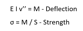
Stiffness is 100% a function of only the area moment of inertia and translates directly to the expected deflection. The governing equation is shown below where v is the deflection. This equation is universal because it consists of an indefinite integral requiring various boundary conditions that can be applied to any situation. (Sorry, I got a little excited there: Math!)
Here is my point: a beam can be stiff with out being strong and strong without being stiff. It is weird, but true. When you consider the shapes below, making a simple change like adding a thin strip of material on the outer fiber takes a strong and stiff beam and makes it weaker, but stiffer. In fact, adding the tiny bit of material to the top and bottom made the section 70% stiffer (Ratio of I values), but only 13% stronger (Ratio of Section Modulus).
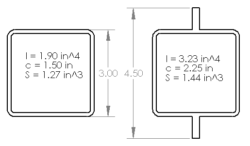
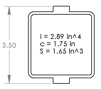
A better design is to lay that same material horizontally keeping more material right at the outer fiber. The result: a 52% increase in stiffness and a 30% increase in strength.
Acing the Test: 20 Years Later – Working an Example
So, I feel it necessary to come back to the scene of the crime and do this test problem again to totally vindicate myself. While I do not remember the exact beam type used, the method is the same. There are (2) I-beams stacked on each other vertically, calculate the section modulus of the combined section. Let’s use a 12 x 22 beam.
| Beam Information | W12 x 22 |
| Area | 6.48 in^2 |
| I | 156 in ^4 |
| h | 12.31 in |
For starters, when we stack 2 identical beams on top of each other, the centroid will be the interface between the beams. We then know that c is the height of the beam (c = h = 12.31in) Nailed It.
We know that I is 156 in^4, but we need to move it from the natural centroid to the new centroid using the parallel axis theorem.
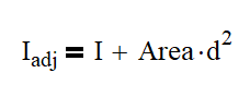
We know the area and the distance we need to move it is half of the height, or 6.16 in. We can calculate that the adjusted area moment of inertia for one beam is 401.5 in^4. We will now need to double that to come up with the Moment of Inertia for the entire section: 803 in^4.
Now, the final step, the one I failed to do so many years ago, I divide I by c. The answer is: 65.2 in^3. Viola!
Can I get the “A” now?
Conclusions
Section Modulus is a very cool tool that allows structural designers to quickly evaluate multiple shapes and thicknesses and see what will and will not work for the application. We can also use this to compare strength and deflection to ensure that the shape selected will perform well.
In the end, I’m glad this experience happened to me. It taught me to read the book along with the lectures, but it gave me something that I will always remember about Dr. Thompson. In case you were wondering, I was able to let this go and attended his retirement several years later and years later. I was saddened to hear of his passing.