Directional control valves are a splendid thing. These hydraulic valves allow us to control the direction of cylinders, hydraulic motors, and any number of other actuators. Valves generally fall into one of three categories:
- Monoblock
- Sectional or
- Cartridge
Valve Types
Monoblock
A monoblock valve is a single piece valve body that is usually made of cast steel. It can have between 1 and 7 (sometimes more) valve sections. Each section has a round bar called a spool in it that slides linearly in a hole that is bored in the body. The body has an inlet side and an outlet side.
Often times, there is a relief port built into the inlet and on most outlets has the option for ‘power beyond‘. The spool has numerous cuts in it that not only control the direction of flow, but also the speed of the flow out and often back into the valve. Incredibly complex things can be done with valve spools and it would take a lifetime to study and understand all of it.
Sectional Valve
A sectional valve is like a monoblock with the major difference being that each valve is its own unique section. If two directional control valves were required, the valve assembly would have 4 sections. They would be Inlet / Section 1 / Section 2 / Outlet.
Generally speaking, there are some nifty options available in a sectional valve that are not available in a monoblock. Some options are, load sense, compensation (pre or post spool) and anti-cavitation.
Cartridge Valves
Cartridge valves are an entirely different monster. These valves consist of two components: a cartridge and a manifold. The manifold has one cavity (sometimes more) and holes are machined to allow oil to flow to and from the cavity to work ports where hydraulic adapters are connected. These manifolds are usually made out of aluminum and can be customized to ridiculously complex designs often integrating dozens of individual cartridges.
Manifolds can also be made to be stackable using ‘DO’ (sometimes referred to as ISO) interface. Interfaces D03, D05 and D08 are the most popular. (Yes it is really D ‘zero’, don’t get me started.)
The cartridges themselves range from simple to quite complex. You can get almost any type of valve in a cartridge form. They are also able to handle very large flows upwards of 100 gpm although you might have to have a smaller valve piloting a larger one.
When you are dealing with directional control cartridge valves, your options are limited. Many solenoid operated valves don’t have mechanical overrides. Because of their versatility, cartridge valves can be seen used in most hydraulic systems and often in monoblock and sectional valves.
Classification
A single valve section is classified by the number of ways and positions they have. Most directional control valves are four-way, three position. What that means it that is that there are four ports or ways into or out of the valve. Positions is the number of different configurations you can put that spool into.
Other classifications are: valve activation and overrides, detent (stays in current position), switches and center position configuration. For example, we might classify a valve as 4 position, 3 way, open center, pilot operated with manual overrides. Yes, that is a mouthful, but each phrase gives you pertinent information about the valve. From this, you could almost recreate the schematic in your head. After all, that is the idea.
Activation
So, let’s talk about what activates these directional control valves. Common methods are:
- Manual – Most valves are manually operated or at least have manual overrides. Levers, footswitches, push buttons or any other contraption you can imagine can be used to slide the spool back and forth.
- Pilot operated valves depend on another fluid to shift the spool. Compressed air can be used, but there is no feathering the valve. The spool will tend to shift all at once. If metering is required, you will need to use hydraulic fluid. In general, pilot pressure is kept around 400 psi and the flow is very low. This is an advantage because we can get multiple control valves very close to the operator, but locate the large valve somewhere else. In mobile equipment, joystick controls are very popular and the low pressures and small lines of piloted controls make that possible.
- Solenoids are electromagnetic coils that shift the spool one way or another. It is dumb technology that shifts fully either one way or the other so there is no feathering of any kind. This type of operation is commonly referred to as “bang-bang”, where the valve is either on or off. A system like this would be referred to as electric over hydraulic.
- Electro-proportional control is how you get more finesse in the system. This is a different mechanism that allows use of a variable electrical signal to control the spool shifting. This is generally done using Pulse Width Modulation (PWM) or current monitoring. To get better accuracy, these systems usually have some sort of feedback from the valve. For valves with large flows, electro-proportional systems have the electronics control a lower pressure fluid where that fluid is used to shift the valve spool. A system like this would be referred to as electric, over pilot, over hydraulic.
Valve schematics
Looking at the figure above each one of the valves is 3 position, 4 way. The positions are shown as left activation, center, and right. The center position is commonly referred to as the first position. If you have a two or three position valve, the first position will be the resting position.
The ways of the port are usually numbered or represented with the letters P, T, A, and B. P is for the pressure line, T returns the oil to the tank or reservoir, and A and B are the work ports, where you would connect a cylinder or motor.
If I shift the valve to the left, the furthest right part is now going to be in the middle where it has access to the ports. In the cases shown above, the P and B would connect and the A and T as well. If I shift the valve right, P and A would be connected.
Note here that the valves have arrows on them and those arrows can have heads on both sides. These are important because trying to have fluid flow the opposite way could cause the valve to close or become unstable.
A practical application is to have the work ports connected to a cylinder with the A port causing it to extend. Shifting to the right allows the cylinder to extend giving a well-defined path between all the ports.
Reversing direction swaps the work ports and the cylinder will extend. In the case of most valves, when I release the controls, the spool is going to stop movement and spring back to center and stay there.
The fun begins in the center position
There are so many option here, but we are only going to discuss the six most common. They are represented above and are nowhere near all the combinations. In fact, I just recently needed to specify a center position where P and A were blocked, but B and T were connected. I know, weird but necessary.
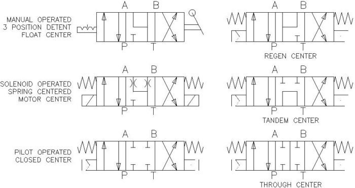
Tandem Center
A tandem center lends itself well to a single valve or a valve at the end of a series of valves. In this center, A and B are blocked and P and T are connected. This allows the constant flow of oil through the valve which is perfect for a gear pump.
The problem with tandem center valves is you can get some pretty weird characteristics if you stack multiple valves like these together. My log splitter has two tandem center valves for the splitting and the jib. It is not an issue because I don’t use both valves at the same time, but still, don’t do this. I will be writing a separate article on this later.
Closed Center
This is where everything is closed and there is no oil flowing anywhere. This is good for holding a cylinder up, but there will be leakage over time. Be very careful and do not use this with something that is moving very fast like a motor.
If you have very high flow rates and you stop it; you are going to have a large water hammer effect on this. If you think about your home’s plumbing, when you shut off a faucet, you can sometimes here the banging of pipes for a second. This is a water hammer. The fluid has momentum that suddenly has nowhere to go.
At your house, the water pressure is only 50 to 60 psi and a flow of 5 gpm. Think of a hydraulic system of 3000 psi and 10 gpm. Please know your system and only choose this for applications where there is not much flow.
Float
This one is very common on closed center hydraulics. This is where the pressure port would be closed and then A and B go to Tank. This prevents any pressure from building up in a work port line.
If this valve was activating a motor, the motor would freely spin until it stopped. However, this would not hold any pressure, so using it to hold a load on a cylinder would not work.
If you choose this option, you would need an alternative method to hold the load like a pilot operated check or counterbalance valve.
Motor Spool
Motor spools are the middle ground between closed center and flow center. What it allows it to do is to bleed off the pressure in the A and B ports quickly and predictably. When using a motor, the closed center builds up pressure instantaneously, and a float center doesn’t build any pressure allowing for a long wind down.
The motor spool (yes, it is named after the function it does) builds up some pressure and this causes the motor to stop quickly and smoothly. If you are holding a load on a cylinder, you will still need to have a counterbalance valve or PO check in between your valve and the cylinder.
Regen Circuit
This is short for a regenerative circuit. A regen circuit is very rarely used. The center position has the P, A, and B ports tied together, and the Tank is blocked. So, if I have a cylinder connected to the A and B port and I pressurize both the A and B ports, most people think nothing happens. That is not true.
What actually happens is the oil pressurizes both sides of the cylinder equally, but the cylinders do not have equal areas. The bore side has a larger area causing a force imbalance. So what will actually happen is the rod will extend very quickly because it only has to move the amount of oil that the rod takes up. This is only the area of the rod. Since you only are moving the area of the rod, you only have the force equal to the rod area. The benefit is that it moves really fast.
Take note that the fluid moving through the center is the flow from the pressure plus the flow from port B. (There is flow from P and B to A). You may need to specify a larger valve or larger work ports to get the operating characteristic you want. This center position gets is name because the flow from port B is reused before going back to the reservoir.
There is a lot of other ways to do this, but a regen center is one of those ways. It is great if you need something to go out quickly, like a log splitter. About the only practical application for this is a cylinder where some clamping force is always needed. In the relaxed state, it clamps with only the force of the rod. If you change the valve position it would give full pressure or retract the cylinder.
Through center
As I mentioned before with a Tandem center you don’t want to stack a whole bunch of these together because it causes undesired consequences. Instead, when you have a series of valves, you must use a through center. This allows you to get consistent pressure and flow when multiple valves are activated simultaneously.
You can see that both of these valves are tied to directly to your pressure line. When you shift the valve, the pressure cannot flow to the next valve section building up pressure that can be used in the active section. If this is a proportional valve, only part of the flow will be blocked, leaving the other sections to perform work as needed.
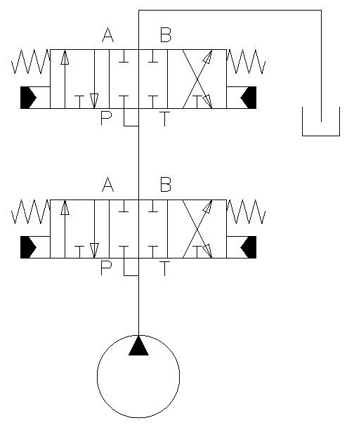
Another benefit of the through section is called power beyond. This allows the flow to power another valve or valves downstream. This is great if you have several different control areas on your machine.
One thing to note is that with each valve in the system, the valves start to have priority. Any valve can take all the available flow, but if multiple different valves are activated, the ones further from the pump will have lower priority. This can be both a detriment and an advantage.
For example, if I had a function that could only be active when nothing else was, I could put this last. This way, it would shut off whenever another function is activated.
Conclusions
In conclusion, directional valves are both complex and simple. They are easy to understand, but designing a system that works well is very complex. After reading this article, you should be able to:
- Understand what ‘ways’ and ‘positions’ are
- Know how valves can be activated and
- Know the main types of center positions and when to use them.