Early in my engineering career, I was overwhelmed by the complexity of the things I was trying to design and calculate. Being a novice, I clammed up and did nothing. On one particular project, an experience colleague asked me where my free body diagram for the design was.
I barely remembered what one was from years past in my Statics course and asked for a few pointers. We worked through it and I started remembering how to use them. It was a difficult process, but once I remembered how to apply a free body diagram, it simplified the problem at hand tremendously.
After applying Free-Body Diagrams nearly daily, it is a much simpler process and often I can see what will happen in my head. (I still highly recommend drawing it out)
A Free Body Diagram is an engineering tool that simplifies a component or system of components to the loads, moments and applied to it in space. The reactions can then be drawn and calculated. The Free Body Diagram can also be used to see if a system is static or dynamic in nature.
How to Make a Free Body Diagram
There several step to making a good free body diagram. The main point here is to simplify the problem. One main idea to keep in mind is that we aren’t concerned with the internal forces. We only want to know how our component(s) interface with external restraints.
Making a Free Body Diagram is a process of drawing a component or system as one simple, immovable solid. Identify the external forces that act upon the body as well as their magnitude and direction. For rigid bodies add dimensions that locate forces. Add in the reactions and rotate the coordinate system if needed.
1. Draw the object
If I’m hanging a TV on the wall and I want to know what the forces are on the mounting bolts, my FBD needs to treat all of the internal components in the TV bracket as one solid body, almost as if it is welded together. Sure, the TV can swivel and move side to side, but I’m not concerned with those forces. I need to simplify my Free Body Diagram to show where the weight of the TV (and perhaps the weight of the mounting bracket) is in relation to the mounting bracket.
The simpler this is, the better! Don’t draw the internal linkages and swivel mechanisms. Keep it simple.
2. Identify the Forces and Moments Acting on the Component
Continuing with the wall mounted TV example, we would then add in the weight (m*g) of the TV as the primary load. We would then need to consider some secondary forces, like what happens when I rotate the TV side to side (yaw) or tilt up and down (roll). Consider if your TV is mounted in a place where some lateral forces (surge and sway) could be applied like earthquakes, or wind in an outdoor application. Is it mounted on a boat. Consider weird loads like centripetal acceleration.
Once you have all these things, you can move to the next step.
3. Draw the Forces on the Diagram
Start drawing these forces on the diagram. Most times you will will know exactly what the magnitude of your forces are. We can easily figure out how much the TV weighs from the manufacture’s data or by using a bathroom scale.
Other forces, like the force it takes to rotate the TV, can be a little harder to figure out. In this case, you will need to make some assumptions. In this case, a normal person can exert about 20 lb without too much effort. I think the it would be safe to assume that a person would grab two corners of the TV and pull with 20 lb on one and push with 20 lb on the other.
As you are doing this, please keep in mind that a force has magnitude and direction. Your are going to need some dimensions and angles to display these forces.
4. Determine the Total Number of Degrees of Freedom
Imagine a space capsule floating through space. (I was thinking about Apollo 13). There is seemingly nothing holding it up and it can rotate and move very easily in any direction. As engineers we need to be able to categorize all possible modes of freedom. We call these Degrees of Freedom.
Mechanical Degrees of Freedom are how a particle or body can move and rotate in space. To remain stationary, all of the degrees of freedom must be restrained. If one or more DoF are not restrained, motion will occur. A 3D particle will have 3 degrees of freedom and a 3D rigid body will have 6 degrees of freedom.
Depending on the type of system we are dealing with, we can have varying degrees of freedom. A particle doesn’t care about rotation, but a rigid body does; therefore, it will have more degrees of freedom. In the same way, a 3D body will have more degrees of freedom than a 2D will.
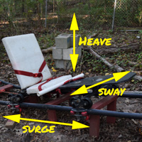
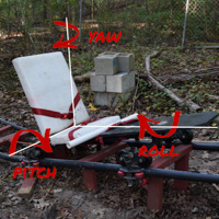
Need picture of roller coaster cart with DoF’s labeled
| Type | Degrees of Freedom | Motion Direction |
| 2D Particle | 2 | Heave, Surge |
| 2D Rigid Body | 3 | Heave, Surge, Pitch |
| 3D Particle | 3 | Heave, Sway, Surge |
| 3D Rigid Body | 6 | Heave, Sway, Surge Pitch, Roll, Yaw |
When creating a model, it is a good idea to see how the design can be simplified. In my experience, I am often able to simplify many 3D problems eliminating 3 degrees of freedom. However, sometimes you can’t because it would over simplify the problem and give you inaccurate results.
5. Determine the Reactions
As you begin restraining your FBD, you will need to add reactions. These reactions need are very important because too few and you have a moving object. If you have to many, you won’t be able to calculate the reactions. We’ll expand on this in the next section.
Reactions are applied to the Free Body Diagram to restrain each degree of freedom. A reaction can restrain as few as one degree of freedom as with a roller or all of them like a fixed restraint. For a static situation, every degree of freedom must be accounted for only once.
2D Reactions
There is a difference in 2D vs 3D reactions, so we will start there since it is the simpler case.
| Reaction Type | DoF Removed | Types | Examples | Representation |
|---|---|---|---|---|
| Normal | 1 | Smooth Surface Roller Rocker Sliding Collar Pin in Slot  |  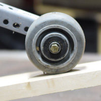 | 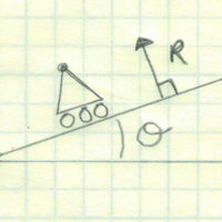 |
| 2 Force Member | 1 | Pinned Link Cable/Chain Spring |  | 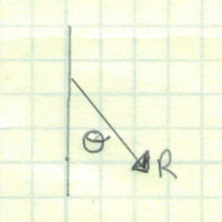 |
| Pin Support | 2 | Frictionless Pin |  | 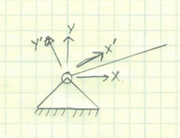 |
| Sliding Fixed Collar | 2 | 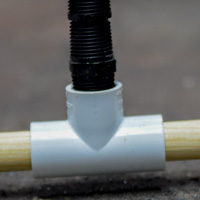 | 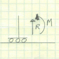 |
|
| Fixed | 3 | Welded or Bolted |  | 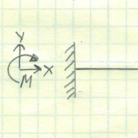 |
3D Reactions
| Reaction Type | DoF Removed | Types | Examples | Representation |
|---|---|---|---|---|
| Normal | 1 | Smooth Surface Roller Rocker Force Normal to Surface | 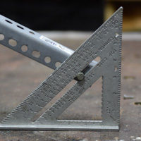 |  Normal to Surface |
| Ball and Socket | 3 | Spherical Bearing Human Hip or Shoulder |  |  Heave, Surge and Sway |
| Pin Support | 4 | Frictionless Pin |  | 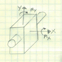 Heave, Surge, Yaw and Pitch |
| Thrust Bearing | 5 | Journal Bearing Smooth Pin Hinge |  | 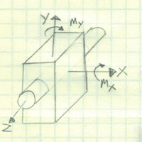 Heave, Sway, Surge, Yaw and Pitch (Can rotate – roll) |
| Square Bearing | 5 | Sliding Joint Preventing Rotation | 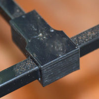 | 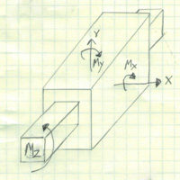 Heave, Sway, Yaw, Roll and Pitch (Can Surge) |
| Fixed | 5 | Welded or Bolted |  | 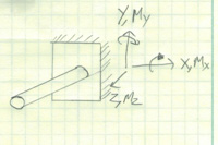 All |
Once you have determined what your reactions are, or at least need to be, add them to your diagram where you want them to be.

6. Select the right coordinate system
By now, you are probably looking at your nearly complete free body diagram with a big smile on your face. Great!
Before we move on to solving the system, we want to take one last opportunity to optimize. We need to make sure that we are using the right coordinate system. This can simplify your task of solving simultaneous equations tremendously.
If we take the classic example of a block sliding down a plane, only the weight of the block is in the direction of a standard x-y coordinate system. This means that every term in X direction needs to be adjusted by an angle and all but one in the y direction.
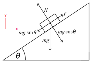
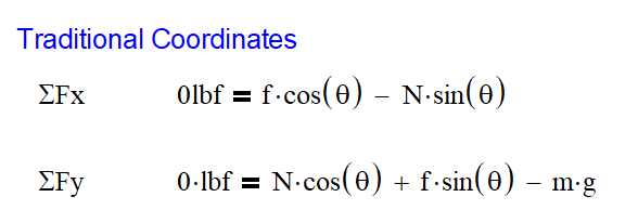
This leads to more work and confusion than is necessary. What we need to do is rotate the axis so that the x direction is now in line with the surface of the plane and the y direction is parallel to the normal force. This simple adjustment in the coordinate system removed all the angles from the equation except for the ones with the weight. It even removed one of the terms!
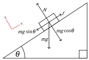
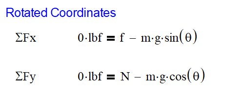
When I setup a free body diagram like the boom arm above, I look to optimize. That usually comes by having the x axis parallel with the length of the boom. Be creative here. I usually end up using Cartesian coordinates, but there may be some cases out there when spherical coordinates are called for.
The article below demonstrates how I rotate coordinates to simplify the problem.
7. Solve the System
We have officially completed our Free Body Diagram and are now ready to setup our equations and solve them. In any single situation, there can be as many as 6 degrees of freedom. This means that we need 6 equations to solve for all the variables. However, the table above indicates that in most cases, we need far less than 6 equations because we have fewer degrees of freedom.
In order to solve a system of equations, we need to have exactly the same number of equations as degrees of freedom. If you have more reactions than degrees of freedom, your situation is statically indeterminate. If you have too few reactions, you will have a dynamic situation.
If you find yourself in an over constrained, statically indeterminate situation, you will need to make some assumptions or consider deflection. Most times, considering deflection will solve your problem. Please read the following article for more information on that.
Reducing Excess Restraints

More often though, over-defining the reactions can be to blame. Take the case of a typical door: it has 3 hinges each taking out 5 of the 6 possible degrees of freedom. That leaves us in a situation of 6 equations with 15 unknown reactions. Very statically indeterminate!
However, this is not the actual case. If we look at the heave load, it is very unlikely that the weight of the door is taken equally by all three hinges. As engineers, we need to assume that only one hinge would support the weight of the door. 2 – reactions removed
Also, each hinge can support the pitch and roll of the door, but in reality, these moments are transmitted to the other hinges because they have a much larger moment arm compared to that of the hinge. This leaves us with only surge and sway loads on each hinge. This is a reduction from 15 to 7 reactions. Getting closer!
Finally, we need to consider why we have a hinge in the middle of the door. (Honestly, I don’t know why there is one. My best guess is to keep the door from bowing) At this point, I would neglect the loads on the middle hinge. They will be much smaller than the top and bottom hinges.
We have now reduced our system to 5 reactions: heave, surge and sway on the top hinge; surge and sway on the bottom. But we have 6 degrees of freedom? What now?
Good question. The final degree of freedom is the yaw or the swing of the door. If we wanted this to be a static condition we could have a reaction where the door latch is or possibly where the door knob would hit the wall and leave a dent. Another possibility is that this is a dynamic problem and the door is moving.
Static vs Dynamic Problems
When setting up our system of equations for the door, we would need to know whether our system is static or dynamic. As in the case of the door above, some can be static and some can be dynamic.
For a system to be static, the forces and moments must equal 0 lb or 0 in-lb. For a dynamic system, forces need to equal m*a and moments equal I*α; where m is the mass, a is the acceleration, I is the mass moment of inertia, and α is the angular acceleration.
Practical Applications
As with everything, examples are the best teacher. This is no exception.
2D Particle
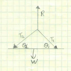
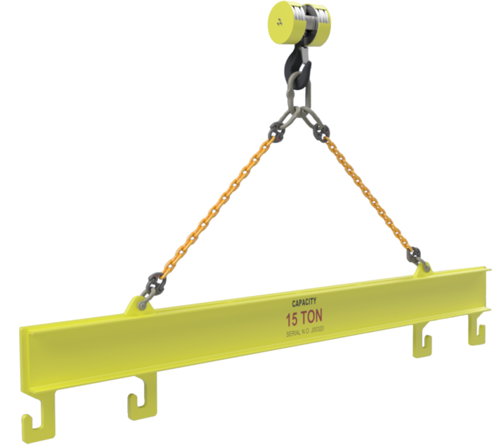
You are most likely to find a 2D particle in a situation where there are ropes or links pinned at a common point. We would have forces in only two directions, X and Y.
3D Particle
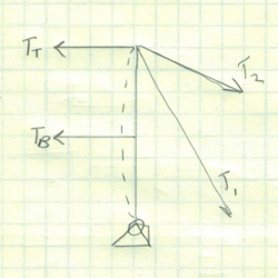
Similar to the above example, a 3D particle example would be a volleyball net held up by guy wires. We now add the variable of height, Z, to our system.
We would need to treat the base of the pole as a normal reaction to the ground and each of the guy wires as a 2 force member.
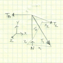

The force applied to tension the bottom half of the net creates a small problem in our system. Part of the load goes up and part goes to the ground. Now we have non-normal forces acting between the pole and the ground. It is now a 3D rigid body problem
2D Rigid Body
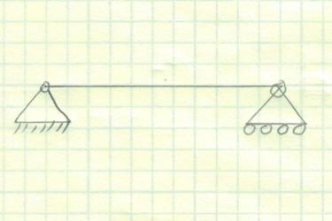
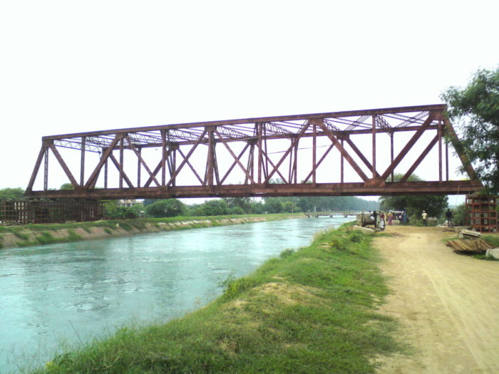
While still maintaining the X, Y equations, we now add in a moment component because the object can pitch. The bridge below is an excellent example of 2D rigid body simplification. If we only wanted to know the reactions of the system, we can simplify it to the diagram below.
3D Rigid Body
This is the catch all for any situations that cannot be solved with the simplifications shown above. In fact, nearly all of these cases could be expanded to easily be a 3D rigid body.
The bridge is the obvious choice for making it a 3D rigid body as we now have many extra reactions in our system. Having an over constrained structure is no different than trying to level a 4 legged table. Get your sugar packets out! Any misalignment of the structure or shifting of the support pillars can cause extra load in the structure or wobble.
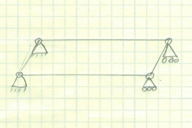
However, with an open lattice structure, like this bridge, it is very flexible and some twisting would be allowed to happen without much change in the bridges stress. I must reinforce that in a traditional free body diagram, everything between the reactions is considered to be infinitely stiff (hence RIGID bodies not soft squishy bodies).
The volleyball net can also be a 3D rigid body if we consider tension on the lower net. The pole contacting the ground would be a spherical joint connection. In this case, 5 of the 6 degrees of freedom are constrained with the Yaw being free.
Where Do I Draw The Boundary?
One of the very cool things about Free Body Diagrams is that they can be created in many ways. Using the bridge below, I can create a simple diagram for the entire bridge, a section of the bridge or even just one member on the bridge. Each of these allows the engineer to approach the overall problem down to the smallest of details.

The boundary of a Free Body Diagram can be changed to give the information the engineer needs. Large diagrams around an entire machine can be created to show how large the reactive forces are. Medium sized diagrams show how a system interfaces with its supports. Small diagrams are used to calculate the stress on a particular component.
In order to determine where you should draw the boundaries for your system, we will first need to determine what you want to know. Generally speaking, it is easier to start with the overall structure and get more and more detailed as needed. Starting off with the details and backing out is more difficult and prone to errors in calculation.
The Challenge
Now that you know a thing or two about free body diagram, can you set these situations up as a FBD? Can these be simplified from a 3D Rigid Body?
