

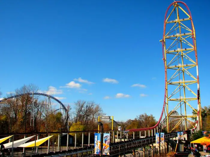
If you’ve ever ridden it, you know the mere 17 second ride on Top Thrill Dragster is nothing less than perfection. You are accelerated to 120 mph (193 kph) in under 4 seconds and then rushed over a 420 foot (128 m) top hat before spiraling vertically back to the ground. Breathtaking.
Intamin Amusement Rides didn’t just build one, it coexists with its big brother Kingda Ka (Six Flag Great Adventure) and little siblings Storm Runner (Hershey Park) and Accelerator (Knott’s Berry Farm). I’ve ridden all of them except Accelerator. (Ironic, because I used to work there.)
Top Thrill Dragster has been dubbed the king of them all because it’s launch is a little more intense. (I believe that Kingda Ka would be better if they removed the over the shoulder restraints)
Top Thrill Dragster is launched by temporarily connecting the train to a “catch car” on the launch track. The catch car is pulled by cables along the launch and cables are wound and unwound on a large reel. The reel is powered by 32 hydraulic motors which are powered by a 2000 hp hydraulic accumulator system.
Launch Sequence
The launch sequence of Top Thrill Dragster is very complicated, but I will simplify it as much as possible. Please note that within each sequence hundreds of individual mechanisms need to be assessed before launch can occur (over 800 total). This means things like the loading gates are closed, all the restraints are locked, brakes are operational and the track ahead is clear. A good comparison is preparation for launching the space shuttle; every system has to give a “go / no go” for launch.
Once the passengers are loaded into the train, two trains advance out of the station. The rear train stops on a holding block section while the other heads to the launch section. At the launch section, the cable drive system will place a catch car under the train. At this point, an electromagnet will energize causing the launch dog on car 3 to lower. You will hear a clank when this happens.
The train brakes will release and roll back about 6 in (150 mm) until the launch dog mates with the catch car. The brake fins are lowered and a final system check is done before launch occurs, accelerating the train to 120 mph in under 4 seconds.
Once the train has passed, the brake fins on the launch will raise up in case the train doesn’t have enough momentum to clear the top. This is call a “rollback” and the train will slow on the launch track. The system will reset and launch will occur again. We will discuss this in more detail later.
Kinematics of Acceleration
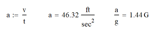
The forces involved to launch the train are nothing short of impressive. If we assume that the launch acceleration is linear or constant, we can calculate the G force is 1.44 times the acceleration due to gravity. Impressive for a launch. Lightning Rod at Dollywood is probably the closest launch to this, but it is aided tremendously by the grade of the launch.
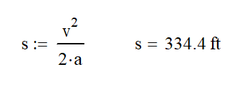
We can also use the following kinematic equation to determine the minimum launch length of 335 ft. We will actually need quite a bit of extra length in the launch for two reasons.
First, there will need to be some wiggle room in the system to tune the launch system. If the train isn’t moving fast enough we need extra launch to get over the top hat. Allowing for 30 ft to 50 ft (9 to 15 m) of extra launch length may do the trick. This section of track could also be used to monitor the train speed before it detaches from the catch car.
Second, we also need a section of launch track for the catch car and cable reel to slow down. The cable launch reel is nearly 7 foot (2.13m) in diameter and carries with it large rotational inertia which can’t be stopped instantaneously. The catch car is also heavy and needs some time and distance to slow down. If we try to slow it down too quickly, we would get the same effect as if you threw a flag pole in your bicycle spokes; you’ll end up snapping a cable or stripping teeth off the gears.
Launch Force
The force involved for launch can be calculated since we know the acceleration using Newton’s Second Law: Force = mass x acceleration. Cedar Point has indicated that a train has a mass of 15 tons (13,600 kg) empty and we can calculate that the average loaded train weight is 16.6 tons (15,000 kg). At first, I couldn’t believe that the trains weighed that much, but then I realized two things.
First, the train brake system works on eddy currents requiring the use of large magnets which are mounted to the train. Magnets are very heavy. Second, Intamin probably wanted the loaded vs unloaded weight of the train to be fairly close so that the ride experience was consistent no matter how full the train was. Having heavy trains would make this difference smaller.
Working out the calculation, we find that the average launch force is 48,000 lb (213 MN).
Cable Drive Launch System
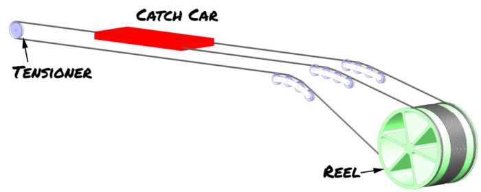
The cable launch system is comprised of a catch car, cables, a reel where the cables are wound and a tensioning device. Let’s look at each of these individually.
Catch Car
The catch car is a long slender component that rolls on a separate set of tracks in the launch system. In the video above, the launch dog attaches to the closest end. It is pulled by two cables for the launch and one cable to pull it back to starting position.
Cable Size
The catch car is pulled by a system of cables. There are two cables that pull the car for the launch and one to return it to the initial position. If the launch system take 48,000 lb, each cable would carry 24,000 lb. In order to safely carry this load, the cable would need to 1 1/2″ (38 mm) in diameter. Returning the cart doesn’t require anywhere near the force.
Generally speaking, wire rope cables are designed to hold 4x the anticipated load, so we would need a cable with a 96,000 lb breaking strength. Also important is the diameter of the sheaves (pulley) the cables are wound on. A good rule of thumb is the diameter of the sheave should be 20 to 30 times the diameter of the cable. The sheave we can see under the train is about a 1″ cable and about 20″ sheave a (20:1 ratio). I estimate these values from several feet away so I might be off.
Cable Tensioner
The cables need to be tensioned to operate properly. If the cables go slack, the ropes will not wind and unwind properly. This could potentially lead to the cables getting tangled or catching on something they shouldn’t. At best, this results in ride downtime. It will most likely result in major structural damage.
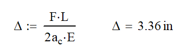
So the next plan is to tension the system and leave it alone. Wrong! Unfortunately, we are applying a very high load for a short time. The cables are going to stretch a lot. Using the formula below for calculating axial deformation (stretching). We find that in an active cable length of 450 ft, we would expect about 3.4″ of stretch at launch.
With cable stretching of this magnitude, we will need to do something more active to keep tension on the system. This is really nothing out of the ordinary. A chain or cable lift hill will also have a tensioning device. Most use weights because of the need for a quick response to changing tension and lack of maintenance. Check out this video if you want to know more.
A traditional weight could be used in this application, but the low distance to the ground creates a challenge. There are 3 possible paths forward; all of which use a sliding tensioner. These are springs or either hydraulic or pneumatic cylinders.
Using springs is the least likely scenario. While they would be the cheapest and lowest maintenance solution, they pose a large problem when maintenance needs to be done on the cable system. To properly tension the cables, you will need to have lots of stored potential energy in the springs. To safely work on the cables, you will want to remove this tension first. The other issue with springs is that they do not provide a constant force as motion occurs. This means that when the cable is longest, there is little tension on it leading to possible slack.
Using a pneumatic or hydraulic cylinder solves the problem of constant force on the cable, provided there is enough pressurized fluid available. Let me explain. When quickly lowering a load on any hydraulic system, we can run into a situation where the volume of replacement oil needed is more than the system can deliver. This happens because gravity is lowering the lift faster than desired. When this occurs, the pressure of the fluid goes to 0 psi and no tensioning occurs. This is called overrun and it is bad.
In order to solve the overrun situation on the tensioner, we need to have a large amount of hydraulic fluid or compressed air ready to fill the cylinder at a high flow rate. The best way to do this is to have an accumulator tank nearby with a large hose running to the cylinder. An accumulator is basically a storage tank of pressurized fluid that is able to accommodate large changes in volume over short amounts of time while keeping the pressure fairly constant. You most likely have one of these in your house called an “expansion tank.” Check out this article for more information.
Cable Reel
At the heart of the cable system is the giant 7 foot (2.1 m) cable reel where the cables are wound. As launch occurs, the two top cables will be winding onto the top of the reel. A third cable, which pulls the catch car back will be unwinding from the bottom of the reel. The reel will need to turn 20.5 times in the 3.8 second launch with a top speed of 540 rpm
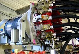
The drum has an external tooth gear on each end where 16 hydraulic motors are attached for a total of 32 motors providing power. Many think that this is a planetary gear system, but it lacks the internal tooth ring gear. In effect, it is one sun gear powered by 16 planet gears.
You will also notice the sound the gears make in the video above. This sounds like my 2000 Saturn SL when I back up. The sound is caused by straight cut (spur) gears. If the gears were helical, where the tooth angles across the face of the gear, the reel would run much quieter.
Total Horse Power
This is actually the wrong question. While spouting off a number might sound impressive, it is irrelevant. I compare it to sizing a light bulb. For so long, we sized light bulbs in watts, but that is not a measure of light, but power. Since compact fluorescents and LEDs came along using far less power, we now have to switch over to how much light or “lumens” the bulb creates. For most of us, this is a totally meaningless number.
Power is a function of Force and Velocity (must be in the same direction). At the speed and weight given, the peak horsepower of the train is 15,300 hp (11.4 MW). However, this power is only at the very last moment before the train and catch car separate. For the initial moment of launch, the power is 0 because there is no motion.
To further illustrate my point, I could power a launch with only one of the 500 hp engines, but it would extend the launch through Gemini and off the end of the island. Not very exciting.
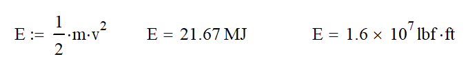
A better way to measure this to look at the energy in the system using the following equation to see that the train has 16 million pound feet of energy. Unfortunately, to most of us, this is a meaningless number.
One more thing to keep in mind here. We have not considered efficiency thus far. Generally speaking, there will be a 15% energy loss in the mechanical system. This is from friction of the cables as the drag on the rollers, the internal stresses of cable flex around the sheave and the rolling resistance of the train.
The hydraulic system may only have a maximum efficiency of 70% At high pressures, pumps and motors are hard to seal and they leak internally which is a loss of efficiency. The main loss is in the accumulator. When pressurized, the nitrogen creates a lot of heat which is released suddenly at launch. The heat radiated from the accumulators is never recovered. This would mean that it might actually take around 25,700 hp to launch the train.
Hydraulic System
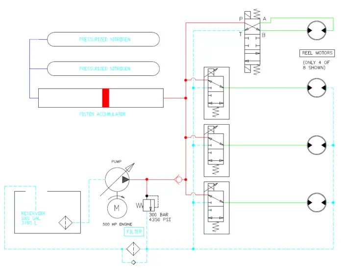
As a Certified Hydraulic Specialist, Top Thrill Dragster makes me happy. It has the largest hydraulic system I’ve ever seen. There are 4 identical systems each having a 500 hp engine! The maximum pressure of the system is 300 bar (4350 psi).
Attached to the engine is a pump that constantly provides pressurized hydraulic fluid. When the ride is not launching, the pumps are resetting the catch car and pressurizing the large accumulators. The accumulators used here are piston style; you can imagine these as a cylinder with no rod. Hydraulic oil is on one side and pressurized nitrogen is on the other.
Accumulator Design
The accumulators are a critical part of the design. For the 45 seconds between launches, pressurized hydraulic fluid is stored here waiting for launch. This ride would not function as it does without them.
A piston style accumulator is definitely the right choice for this application, because it allows for easy expansion of the nitrogen gas. In this case, we can have the accumulator go from all the way full (piston at left) to all the way empty. In a traditional accumulator, there will always be some gas in the accumulator.
Having the pressurized nitrogen in separate pressure vessels leads to lower costs and easier placing of components (it doesn’t have to be in one really long component). Most importantly, it allows the pressure to be more even regardless of piston position.
Launch
Once the accumulators are full, the system can launch. At this point, cartridge valves open using an electric solenoids. Fluid flows from the accumulator and pump to the 8 motors on each subsystem. Most of this flow is from the stored fluid in the accumulators.
One of the coolest functions of a hydraulic system is the fact that oil is nearly incompressible. This allows for accurate control of the output (train speed) of the system. I’m sure that there is a rotary encoder on the reel that tells the computer exactly what position the catch car is in and exactly what speed it is going. This means that the computer can adjust the flow to the motors if the train is going too fast or too slow.
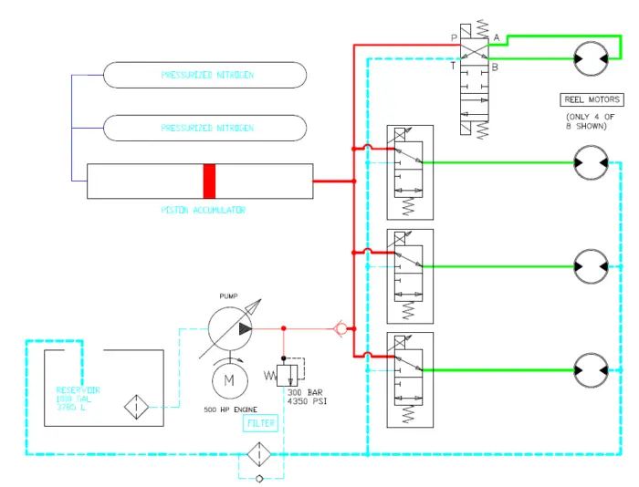
At the beginning of the launch, there is no flow through the motors only pressure. This starts the rotation of the motor and reel. The flow will increase until the target speed is reached and the system will slow down. The pressure should remain the same for the entire launch.
To ease comfort for the rider, the control valves will be proportional. The computer will slowly open the valves at the beginning and slowly close them at the end. Once the train reaches full speed, these valves will start to close and the launch will stop.
Resetting the System
I’ll be honest here, I’m using my best guess on this section. As the catch car is moved back to the initial position, I believe that they use the hydraulic system to do it. Why would you want to introduce a new system here? The question is how.
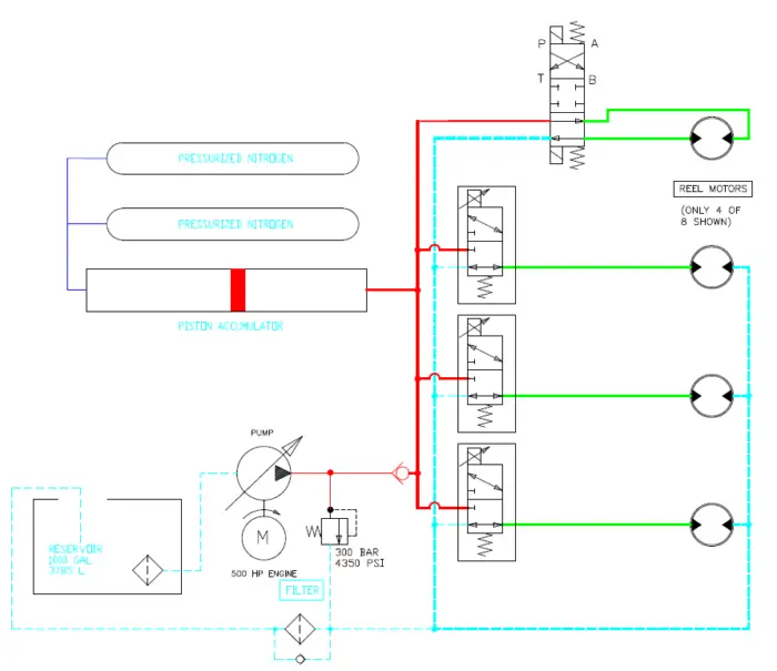
Since there is not as much load to reset, you wouldn’t want to use all 32 motors to do it. That would be a waste of oil and would take much longer to get the system ready for launch. I speculate that only one motor per system reverses the reel. The rest of the hydraulic motors would free spin; recycling the oil from one port to another. This motor is also used to lock the reel while the others can free spin.
Rollback
One of the cool things about Top Thrill Dragster is that it can rollback if it doesn’t clear the top hat. Don’t worry, it is designed for that. As soon as the train passes, brake fins extend up to stop the train. These fins don’t actually contact the train, but slide between magnets located on the train. This phenomenon creates a magnetic field which creates an eddy current in the plate which resists the motion of the train. Since motion is required to create the current, the fins can never fully stop the train so another mechanism is needed to actually stop it.
One important thing to consider is that if there is a rollback, you don’t want the train to reattach to the catch car. That would probably destroy the ride and injure everyone on board the train.
The launch dog, mounted on car 3, is naturally held up either by spring or magnet so that it cannot make contact with the catch car. Before launch, you will hear a clang and then the train will rollback about 6 inches. The clang is caused by an electromagnet beneath the train pulling the launch dog down. Once down and engaged with the catch car, it is mechanically latched and the electromagnet deactivates.
Issues
As you can imagine, this is one complicated machine! It has it all: cables, wheels, hydraulics, giant spinning wheels, hundreds of sensors and a giant control system to go with it.
With each of these components and systems, there is a risk for malfunction which will shut down the ride. As you can imagine, this ride sees quite a bit of downtime. However, in the last decade, the maintenance team has become a well oiled machine and have been able to keep it running more often.
As the ride is nearing 20 years old, we hope that it will continue to operate for another 20 years! See you there.