

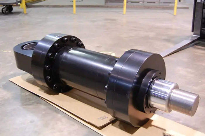
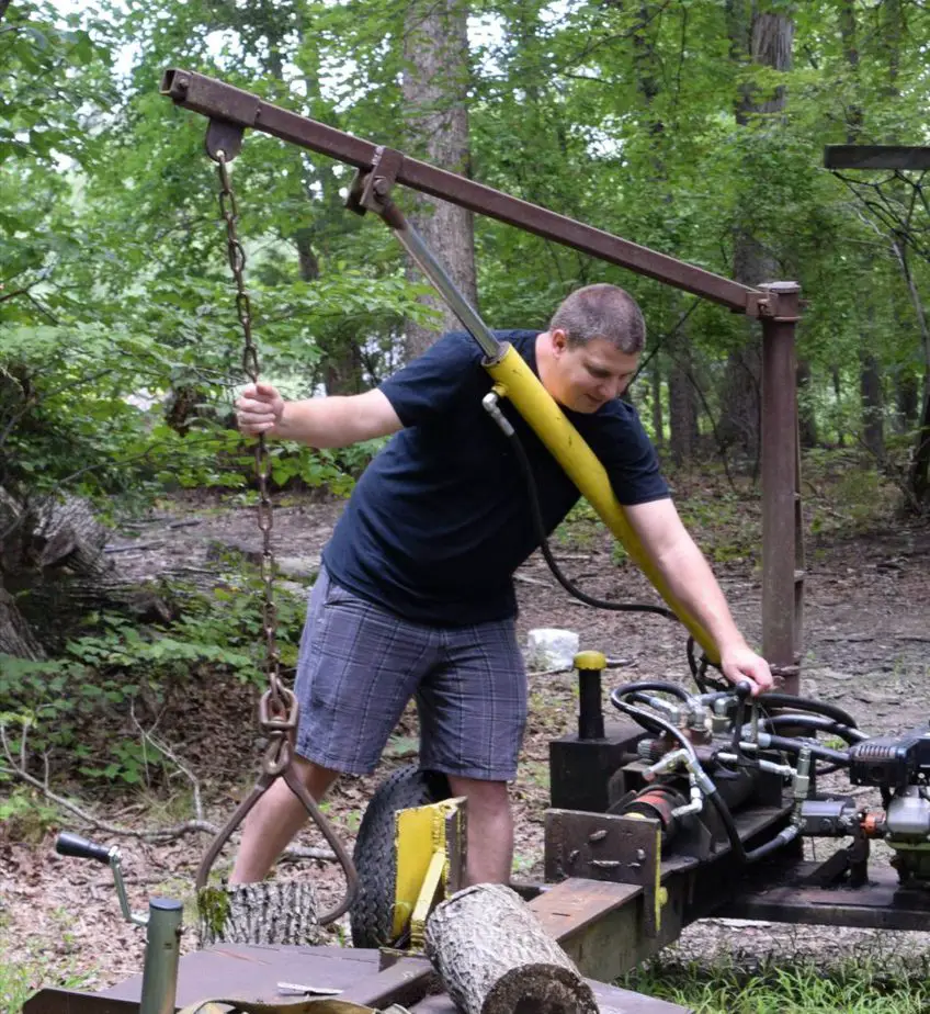
I was over at my neighbor’s house watching him split wood. His father and uncle had built this log splitter nearly 20 years ago. Being that this was some redneck engineering going on, it worked, but was incredibly slow. It took forever for the cylinder to retract and even longer to extend.
At the time, I was studying for my hydraulic specialist certification and just learned about regenerative hydraulic circuits. I wanted to use it. I offered that I could speed up the system if he would let me borrow it from time to time. He agreed.
A hydraulic cylinder can extend faster with a regenerative circuit at the expense of reduced extension force The entire cylinder can be sped up with the addition of a two (or more) stage pump. A multistage pump will offer high speeds at low pressures and low speed at high pressure.
Let’s explore this hydraulic voodoo magic!
Regenerative Circuits
Question: What happens when you pressurize both ports of a hydraulic cylinder?
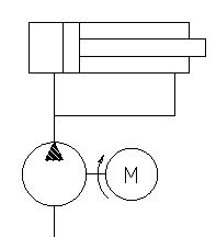
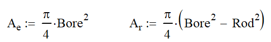
If you said,”Nothing, it will have equal pressures on both sides of the piston,” you would be wrong. You do have equal pressures but you don’t have equal areas. The areas on both sides of the pistons are calculated below.
So the resulting motion is the cylinder extending with oil flowing out of the rod end and back into the barrel. This oil from the rod is the regenerating fluid from where the name of the circuit comes from.
Since you’re smart, you probably already noticed that there is a trade off: loss of force. When you pressurize both sides of the cylinder, the annulus areas cancel out and you are left with just the area that the rod takes up. This reduces the available force to the pressure times the rod area. So there is a definite trade off.
Full Time Regenerative Circuits
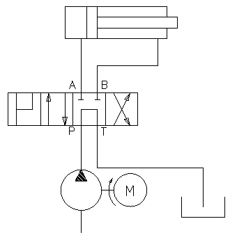
A couple of well placed check valves can turn any hydraulic circuit into a full time “regen” circuit. As the cylinder is extended, fluid flows into both ports of the cylinder. The oil must flow out of the rod end, but cannot flow directly back into the barrel end. It makes its way through the other check valve and combines with the inlet flow. Viola – extra flow for the barrel end of the cylinder.
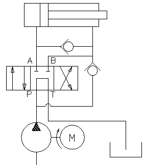
When I shift the valve to reverse, the circuit functions as normal.
The major downside to a Full Time Regen Circuit is that it is full time. I don’t ever get the maximum force available from the cylinder. In applications like my log splitter, I need that force.
Part Time Regenerative Circuits
There are a few ways to slice this pie. The easiest is to add a needle valve on the rod port. This will drain off the pressure and allow the barrel end of the cylinder to create more force. However, a substantial amount of flow is needed, aka wasted, all the time and it slows down extend speed.
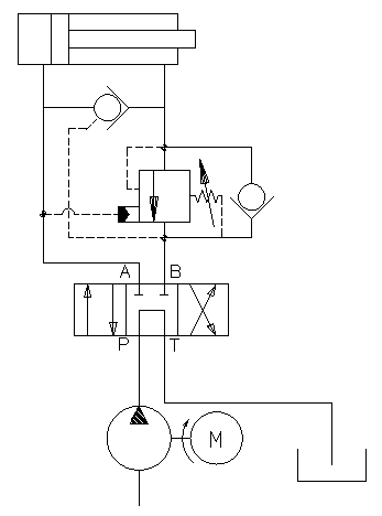
Using a counterbalance valve is a better way to go. At low pressures, fluid will flow from the rod to the barrel through the check valve. (Note that the check valve orientation is reversed from above.) At higher pressure, the barrel pressure will open the counterbalance valve and dump all of the rod flow to tank once the set pressure has been exceeded.
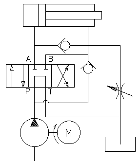
If you want to get fancy, you can use a 4 position 4 way valve. Three of the four positions will work normally, but the fourth position will have the regenerative circuit. With the extra position, you can determine exactly when it is necessary to have the regen circuit.
Two Stage Pumps
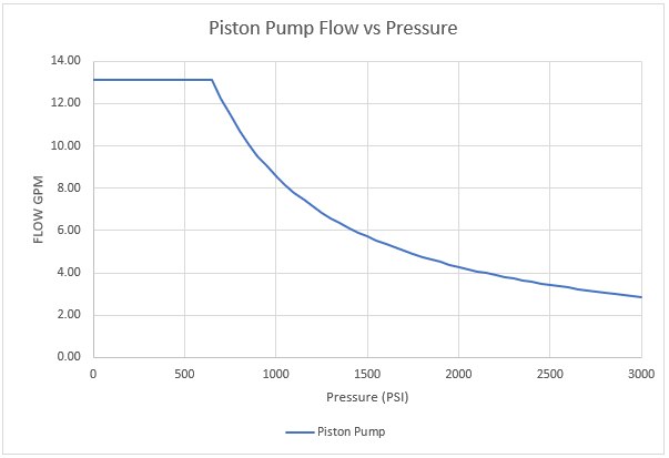
Ideally, we would want our pump to put out the maximum flow available for the prime mover’s rated horsepower. The only way to get that is to use a variable displacement piston pump in combination with a torque limiter. This is expensive $$$! A typical pressure flow chart for a torque limited piston pump is show below. (Note that power = pressure x flow.)
The solution is to use two or more cheap gear pumps and turn them off at higher pressures. Ok, so we don’t actually turn them off; we simply dump the flow to tank or recirculate it back to the inlet (shown below).
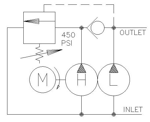
We can see that our two pumps are always connected to the shaft and our motor or engine will turn the shaft. The pump on the left is the high displacement or high flow pump and the one on the right is the low flow pump. Since they are gear pumps, every revolution produces the same amount of fluid in the pressure port. At low pressures, the two flows are combined at the outlet as the high flow pump moves oil through the check valve. This gives us our high flow rate.
In a log splitter, this would be used to run the system right up to the log that needs splitting. As the cylinder starts to exert force on the log, the pressure will build. At the current high flow, even medium pressures will stall out the motor. It is time to turn off the high flow pump!
Luckily, turning off the pump is quite simple and only involves two components: a check valve and an unloader valve. The check valve is there to keep the higher-pressure oil from the low flow pump separate from the oil in the high flow pump. The higher-pressure oil from the low flow pump will shift the unloader valve by compressing the spring. This allows flow from the high flow pump to return to the suction line of the pump.
Many pumps have this return line internal to the pump, so there is no additional plumbing needed. At this point, the high flow pump uses little to no power to perform this action. You will notice that the cylinder speed slows dramatically. As the log splits apart, the pressure may drop causing the unloader valve to close again. At this point, the flows will combine again. This process may repeat several times during a single split.
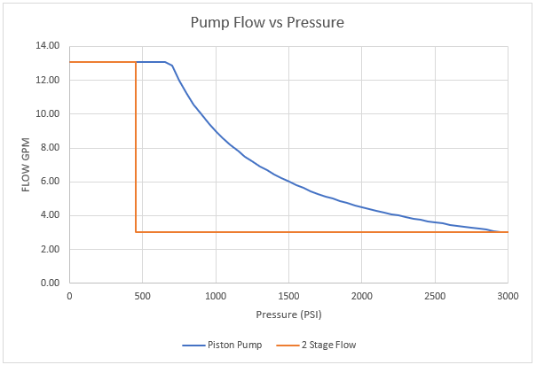
The chart above shows the performance curve of the piston pump and a two stage pump. The two stage gives high flow at low pressures and low flow at high pressures. Easy and cheap.
For more information on two stage pumps, check out this article.
Using a two stage pump can have undesired complications. For example, my log splitter has a jib hoist on it as well that is hydraulic powered. When I am lifting or lowering the load, I might see a change in speed when the high flow pump cuts out. If I am operating in this unsafe condition shown, a sudden speed up could have disastrous consequences.
In order to mitigate that risk, I installed a counterbalance valve on the jib cylinder (it should have one anyway for load holding). The weight of the jib and load is enough disable the high flow pump. The c/b valve mostly helps with the lowering because it requires higher pressure to allow flow from the barrel back to tank.
I set the pressure so that it needs 1000 psi to lower the boom which is well over the cutoff for the two stage pump.
Summary
My log splitter performance was greatly improved by adding a two stage pump. I have also considered “upgrading” by adding a part time regenerative circuit using a counterbalance valve. This would help improve performance and speed up the process. I don’t know if it is financially worth it…..