In a gear system it is critically important to understand how much power can be transmitted. The main limitation is usually the gear tooth itself.
Calculating the forces on a gear tooth reduces down to calculating the tangential, radial and axial force on the gear. Then the stress can be calculated on the tooth and a speed factor can be applied for high speed operations. This will ensure long life of your gears.
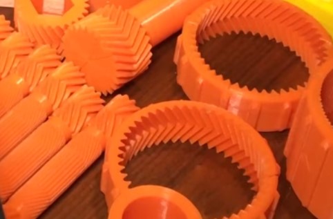
Spur Gear Forces
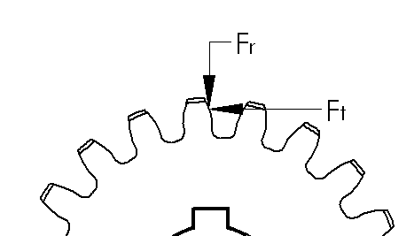
The first thing we’re going to do is create a quick free body diagram on a gear tooth. We can make our calculations based on the pitch circle diameter. We have the tangential force, Ft which is the input force that transmits motion. We can find the tangential force from the torque on the gear.

Where Ft is the tangential force, T is the applied torque and d is the pitch diameter of the gear.
Because of the gear’s pressure angle, we now have a radial force, Fr, that pushes the gears apart. As you can see, having a higher pressure angle will create higher radial forces. To maximize efficiency, ball or roller bearings are often used even when rotation speeds may be slow enough to use cylindrical or other non-moving bearings.
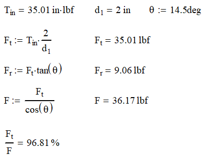
By solving for the statics, we can find Fr and the total force F. The total force is almost a useless number, but it does give some indication of how efficient the system is. The higher the ratio of Ft/F is, the more efficient the teeth are.
If have a 14.5° gear with a diameter of 2 in that needs to transmit 35 in-lb, we find that the forces on the gears are as follows:
Helical gears have an added level of complexity not only in design, but also calculation.
Helical Gear Forces
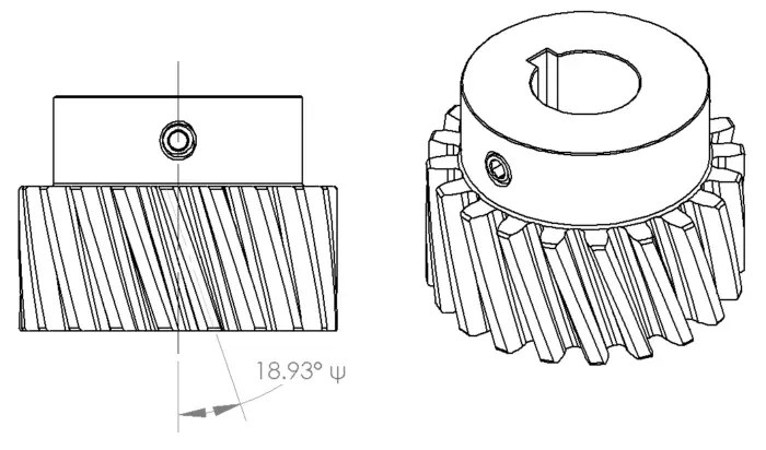
In the gear above we still have a 14.5° pressure angle, but the teeth are cut at a 18.93° angle from the shaft axis, represented by ψ. From the diagram below, we slice the gear two ways with θt equal to the gears pressure angle and θn which the pressure angle when viewed from the end of the gear. Now we can start calculating our gear forces.

Since the gear tooth is cut at an angle to the rotation axis, it should be no surprise that we are now going to have an axial component (along the shaft) in our calculation.
As a result, you will need to think of how you want to deal with this load. Having a set screw taking this load might be acceptable if you are using small torques, but you will probably need to upgrade to tapered roller bearings or thrust washers if your loads are high.
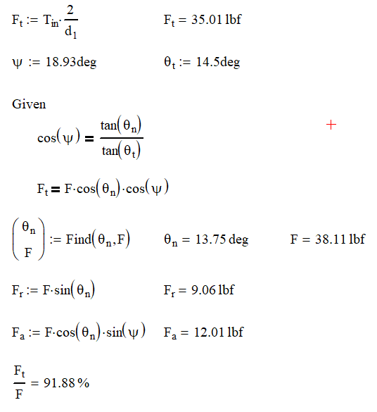
Obviously, having the axial component will decrease our overall efficiency of the system as our ratio of tangential force to total force dropped from 97% to 92%.
One thing to note about changing from our spur gear is that the radial force remains the same.
Calculating the Tooth Force
There is a lot that goes into the design of a gear tooth. Now I don’t know all the specifics of tooth design and more importantly, I don’t want to burden you with them either. But somebody has thought this out, done a lot of careful planning and lot of calculation on tooth design. Let’s leave this subject to the experts and build off their theory, knowing that it works.
Involute Tooth Profile
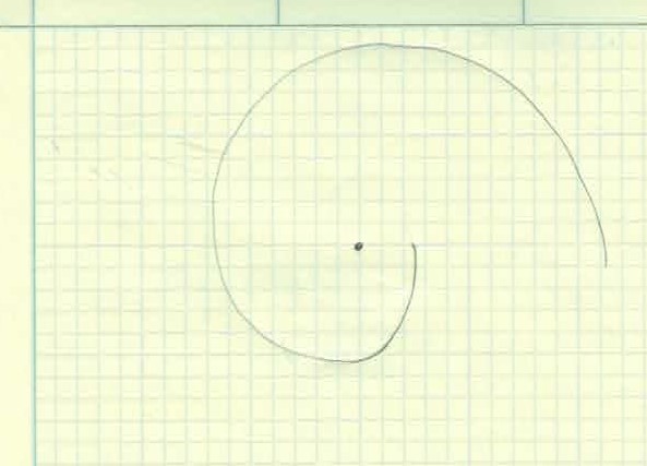
Gear teeth are designed with the unique profile and it’s called an involute profile. The involute profile is made by taking a string and wrapping it around a cylinder. We then trace the curve of the end of the string as it unwinds. As you can see, a curve with a constantly increasing radius is made. This is very similar to the Fibonacci Curve sometimes known as the Golden Spiral.
The section of the involute curve we use is determined by how close or far away from the center cylinder and how big the cylinder is to begin with. Once again, let’s leave that to the experts and just go on their theory and know that it works.
So, it all comes down to the force and stress exerted on the tooth. For as complicated as the gear tooth profile is and all the points that the gears contact; the formula is surprisingly simple.
Those really smart guys that came up with the involute profile; this is where they really earned their money.

Where Ft is the tangential force, σa is the allowable stress, w is the effective width of the gear, Y is the Lewis form factor and PD is the diametric pitch. As always, watch your units. For this example, you can stay in pounds and inches.
Lewis Form Factor

The Lewis Form Factor is the real genius of the operation. This factor takes in all the geometric variances with the involute profile and puts them in a neat little table shown here. You can see that increasing the number of teeth increases the factor as well as going to a higher pressure angle.

If you want to increase your tooth capability, you can increase your allowable stress, gear width, or use larger or higher pressure angle gears. You can also decrease the diametric pitch, because fewer teeth per inch means larger (and stronger) teeth.
Barth Speed Factor
The equation above is great for finding the allowable stress for static gear meshing or those running at very low speeds. Unfortunately, we probably want our gear systems to run at higher speed so we need to add in a factor to account for speed.

Adding the Barth Speed Factor, kd, decreases the allowable tangential force. The gear speed is the velocity of the teeth at the pitch diameter measured in ft/min. The constant a is based on gear design and is 600 ft/min for regular gears and 1200 ft/min for precision gears.
Example
If we continue the example from above with the gear running a 1800 rpm, we can calculate the Barth Speed Factor.

From there, we can calculate the allowable stress from a 40 tooth, 20 DP 1/2″ wide gear.

From the chart above, we find that a 40 tooth gear with a 14.5° pressure angle will have a Lewis Form Factor, Y, of 0.336. Completing the calculation with give a stress of 5200 psi.
This is minimum yield stress of the material required. This eliminates most plastics and some aluminum gears as options. There are many brass and steel materials that could be used for this application.
What is the Allowable Stress?
With these equations, you should be able to calculate the tangential force. We are only thing missing is the allowable stress. Unfortunately, I cannot give an easy answer. I can only give the lawyer answer: It depends. Here are some of the factors that will play a role in calculating the allowable stress
- Hertzian contact stress
- Gear ratio
- Material
- Surface roughness
- Lubrication
- Overload
- Dynamic Load
- Temperature
Each of these factors can be very hard to determine. I wish I could be of more help, but every case is different. My advice to you is this, go conservative! Calculate the maximum load that system can see and use a design factor or 3:1 on yield stress. Make sure that your gears are well lubricated as well. Designing to these criteria will put you on the side of caution. Remember nobody complains if your gear system lasts forever.
Conclusion
Gear systems are everywhere and fun to design. Calculating the torque that can be transmitted through gear systems is important in machine design. Fortunately, these calculations are relatively simple and straight forward.
If you want to know more, check out these posts.

