A few months ago I commented on a post of a very impressive wooden bridge contest (LinkedIn post below). I made the comment: “Excellent use of the vertical ‘zero force members’ in the center…” Well if there is no force on the member, what purpose does it have?
A Zero Force Member can be used to stabilize other members in the structure in compressive loads from buckling under a column load. By supporting a member at the midpoint, you can increase the critical buckling load by a factor of 4.
What Is a Zero Force Member
A Zero Force Member in a truss structure is a member that attaches to a node in which any force would cause static instability. The most common example of this is two members in line and a third member at the node coming in at any angle. The third member has Zero Force.
A truss structure is made up of nodes linked together by members. The node it self is considered a pinned joint (this might not always be the case); therefore, it is able to pivot and cannot support a bending load. As a result, the forces summed at the pin must cancel out to zero.
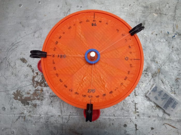
We can treat the above force table as a pinned joint in the truss with three members. F1 acts at 35°, F2 at 180° and F3 and 270°. In order for the blue ring to stay off the aluminum center pin, the forces must balance out in both the X (left / right) and Y (top / bottom) directions. That is accomplished by using the two following equations.
Σ Fx = 0 lb = F1 cos(35°) – F2
Σ Fy = 0 lb = F1 sin(35°) – F3
If we know F1, F2, or F3, we can find the other two values.
Locating a Zero Force Member in a Truss
Zero force members are easy to look for when you know what you are looking for. Be on the lookout for two members 180° apart and a third one that comes in at a different angle. See below.
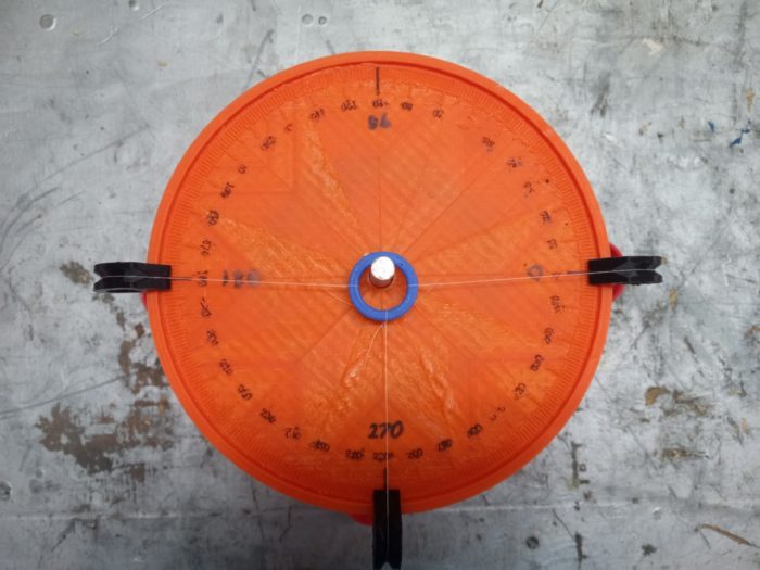
The main two forces come in at 0° and 180°. For this to balance, in the X direction as shown below.
Σ Fx = 0 lb = F1 – F2
When the force at 270° is applied, it will pull the ring down under any amount of load. This happens at any load and can mathematically be expressed as this.
Σ Fy = 0 lb = F3 sin(270)
The Y equation above mandates that F3 = 0 lb at any angle (except 0° and 180°). F3 is by definition a Zero Force Member and cannot take any load.
If there is another member present or an external force applied, F3 may not be a zero force member. So be careful.

How Does a Zero Force Member Help In Buckling
The buckling formula is Pcr=n2*E*I/L2. The variable n represents the harmonic plus 1. For a free span column, n is 1. If we support the column at the midspan, we now force the column to deform at the first harmonic and n is now 2, making it four times as strong.
Buckling of columns can be a hidden danger. In the bridge truss above, the bottom member is in tension and the top member is in compression. This means that the top member is subject to a hidden failure mode.
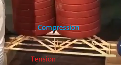
If you are wondering how I determined so easily I was able to determine this without math, I removed these members in my mind and asked which way the structure moves. When I remove the top member, the structure will bend down requiring a force under each load pushing out (compression). When I remove the bottom member, structure still bends down, but a force pulling in (tension) at each support is needed.
Once we determine which members are in compression and subject to buckling, we might want to support them. In the bridge truss above, the node in the top member at the center has a zero force member pointing down. There is no way that the member can take load.
But this vertical member does serve a critical purpose. It prevents the horizontal member from buckling by changing the harmonic at which it can buckle. The standard Euler buckling equation is as follows.
Pcr=n2*E*I/L2
Where, Pcr is the critical buckling load, n is the harmonic + 1, E is the modulus of elasticity, I is the area moment of inertia and L is the length. When we keep E, I and L the same, that leaves us only n to vary if we want more buckling strength.
Failure in Buckling
If we look at how members in buckling fail, we notice that like this ruler below, the center will bow out at the middle (red line). This is a zero harmonic failure mode, where n=1. When we grab a hold of the center, we have now changed the failure mode so that it is likely the ruler will failure at 1/4 and 3/4 of the length. This is illustrated by the blue line below and is the first harmonic.
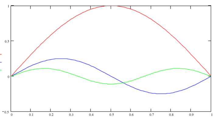
Notice how the amplitude of the orange curve is so much less than that of the black curve. This is caused because more force is required to make this deflection happen. The increase in buckling strength is 4x that of the natural frequency.
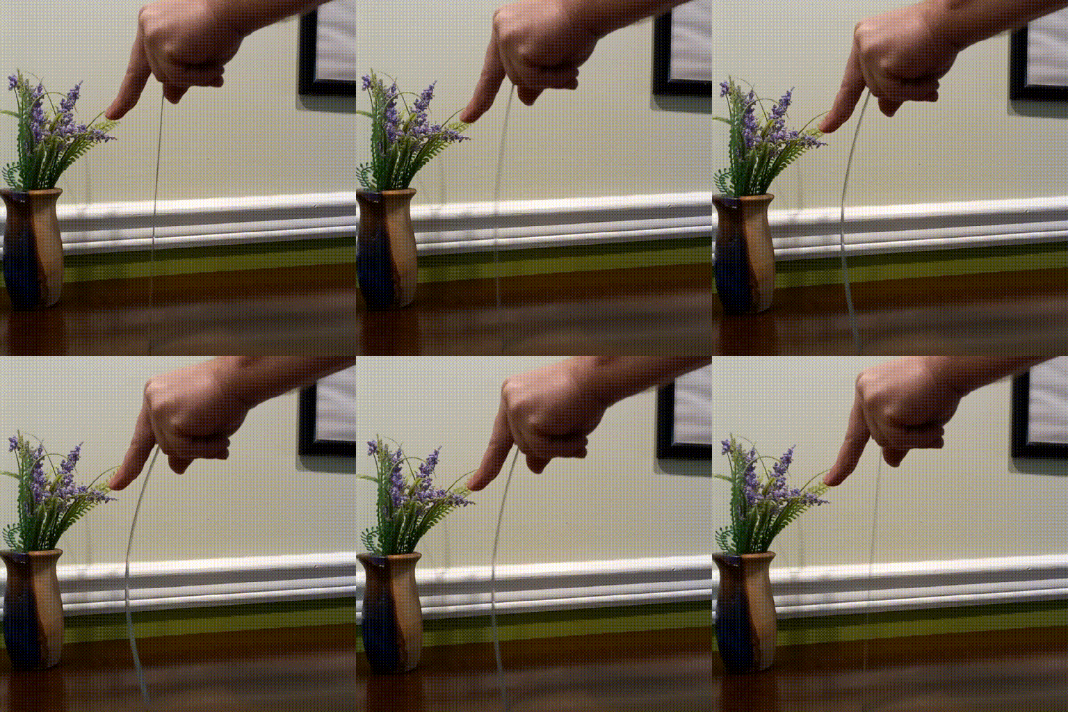
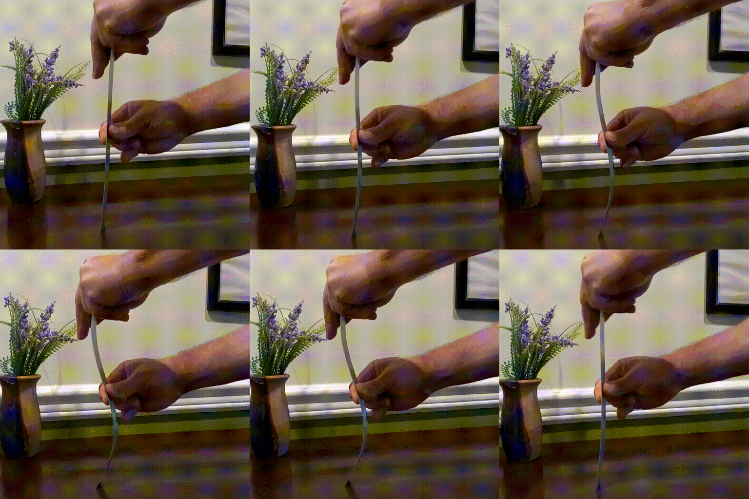
When we increase to the second harmonic, we see a displacement of zero at 1/3 and 2/3 the length and the amplitude decreases again. The buckling strength is now 9x that of the natural frequency.
Summary
Zero force members do serve a critical role in truss structures even though they don’t take any force. By preventing buckling on long compressive members, they allow engineers to use the materials better leading to lighter and stronger structures.


