

I have always said, “There is no such thing as a quick FEA.” In my opinion, FEA is one of the slowest tools in our tool belt. It seems like it would speed things up by not having to do hand calculations, but that is rarely the case.
The truth is that FEA should only be used to verify our design after hand calculations have been completed. (More to come on this in a future article)
FEA run time can be drastically reduced, by making modeling changes to pins and cylinders. These changes allow the removal of contact sets and treating the components as bonded. This can be done while still maintaining accuracy of the results.
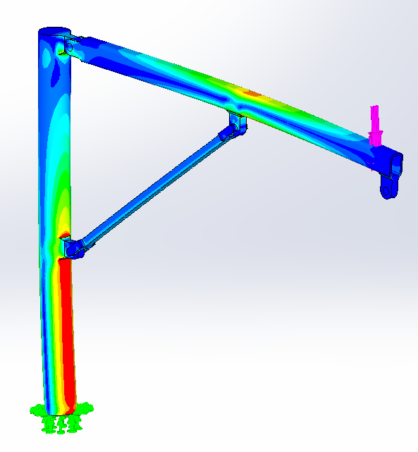
We often come upon situations like what is shown below: a simple jib with a hinged pin joint and a cylinder to articulate. Using traditional FEA practices, this can take significant processing time.
With a few simple changes, we can reduce the processing time by nearly 50% without losing accuracy.
Contact sets take so much more time to solve than bonded components
FEA run time can be drastically reduced, by making modeling changes to pins and cylinders. These changes allow the removal of contact sets and treating the components as bonded. This can be done while still maintaining accuracy of the results.


The image above on the left shows how an actual pin would react when loaded. This simulation is achieved by using no penetration contacts in Solidworks Simulation. Contacts take so much more time to solve than welded components (shown on the right). Sadly, the welded analysis is not accurate and this joint can take moment now. Furthermore, there are no gaps: a pin only pushes against one side; this will pull as well.
Don’t you wish there was a way to get accurate FEA results, but run in the time it takes for a welded simulation to run?
Well in some cases you can. Below on the left is the model with contacts. It took 165 seconds to run and gives great results (longer if I used friction in the joint). The model on the right has no contacts and ran in 24 seconds (85% less time).
If you look at the points of interest on the structure and not the pin or cylinder, you really can’t see a difference between the two models.


Really the only striking difference is at the hinge joint where the loads on the clevis are much different.
Let’s see how we can improve your FEA run time.
Cylinders
Unless you are a cylinder designer, you probably don’t care about the internal stresses on the cylinder. (If you are a cylinder designer, don’t use this tip.) As a result we can use this to our advantage.
Cylinders are the first step to minimizing FEA run time. For the example above, there was a 45% reduction in run time just remodeling the cylinder to be a weldment and not use a contact set.
When sizing a cylinder, we generally know what size bore and rod we will need. From these numbers, we can calculate the stress on the pin and determine a proper diameter. (You can use my double shear pin calculator if you like).
How is it Possible?
A cylinder is a two force member so we know which way the forces go. They are either tension or compression. The main exception is a piggyback cylinder that will carry moment along the entire length. (We don’t want any side load on our cylinder either.)
As a result, we can change the end configuration of the rod and bore to simulate the cylinder reactions in one direction. We can also incorporate the pin into the cylinder component reducing our part count from 3 to 1. Most excellent!
On top of that, we can treat the cylinder and what it attaches to as one weldment. This is the main step to reducing FEA run time.
The center section of our cylinder will have a cross section of 1 inch squared. I always use this cross section for a few reasons.
- Any rotational deflection will be minimal. A cross section this small does not resist bending on the end very well so it will always be the weaker member and flex first. As a result, the top and bottom faces of the cylinder may have additional tension and compression stresses. (I’ll deal with that in a minute.)
- Linear finite element analysis will ignore buckling – Having a really small cross section doesn’t matter in linear analysis. The computer just sees the member as a bunch of points in a matrix. The operator would need to determine if buckling is an issue. Obviously, this won’t be an issue in tension cylinder application.
- The stress will equal the force. If you have 25 ksi on the FEA results, you will have 25,000 lb as the cylinder load. This will be a quick way to check if your calculations match your FEA model. If it doesn’t, you will want to check your calculations and your FEA. I always create a small split line section on the sides of the cylinder where I refine the mesh and take my readings. You will want to make the split line section around the neutral axis and half the height of the beam.
How to Model a Male Clevis Cylinder for FEA
1. Model the Main Shaft of the Cylinder
Start with the slot feature and make the slot 1 inch high and the desired length of the cylinder. You can use configurations to have multiple lengths, although you most likely just need the retracted and extended length.

You will then want to extrude it about the midplane to a width of 1 inch.

2. Model the Pins
Extrude the pin as shown below for any male clevis type attachment. Notice the lip around the outer 1/4 of the surface. This allows us to have a bonded connection with the bore of the mating hole. This is the change saves us the run time in FEA.
Since our cylinder is used in compression, we have it on the outside of the the model. If the cylinder was in compression, it would be used on the inside.


3. Model the Tube
At this point, the tube can be a simple midplane extrusion with no inside diameter. We are losing some detail here, but we are not concerned with the stresses on the cylinder or pin. We can calculate those by hand easily enough. (Actually, we should have done that before the FEA process began.)


4. Remove Contact Sets from Assembly
Now that we have our cool cylinder part, we need to insert this and mate it in the model. We also need to remove any contact sets that may be lingering.
5. Measuring Cylinder Force / Stress
After the analysis has run, right click on the stress plot and select “List Selected” from the pop-out menu.
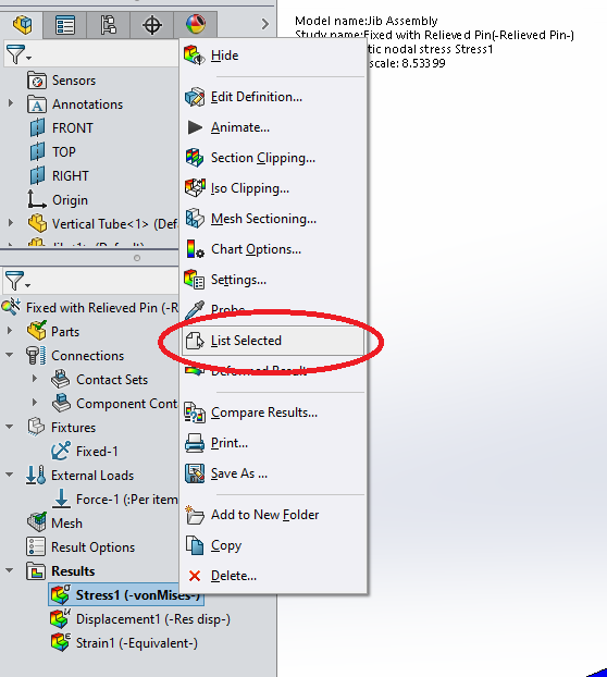
Then select the two split lines on the side of the cylinder, click update and look at the average stress. If your cylinder shown signs of bending, as is the case below, this number will be a little higher than expected. If this is an issue, you can simply make the split line section narrower to be closer to the neutral axis.

Modeling a Cylinder with a Female Clevis
1. Start with the Pins
The female clevis is constructed differently so we need to approach it differently. With any cylinder, we are very concerned about the length. This is easy to control in the male cylinder with the slot extrusion first. With the female version, it is easier to start off with the pins an work our way to the center.

Start by modeling the sketch above, adjusting the outer diameter to your bore, and extruding to the effective length of the pin.
2. Extrude the Shaft of the Cylinder
Drawing a ‘I’ section on (usually) the top plane, creates the shaft of the cylinder. We will want to make the thickness of the shaft and flange of the ‘I’ all one inch. We will extrude one inch so that we keep the shaft at 1 square inch in cross section.

The ends of the beam are shown 1.75 inches away from the center of the pin. This length is arbitrary. We want to keep it as short as possible, but we don’t want it to interfere with the mating components.
Two final things to note is that the width of the flange will be coincident with the end of the pins and the shaft will be symmetric with the length of the pin.
3. Join the Components.
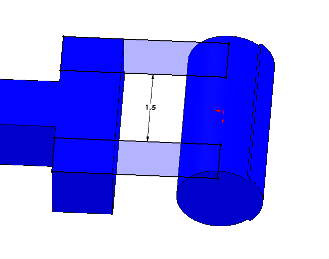
The next step is to join all the individual bodies together. Sketch two rectangles on the top of the ‘I’ section to the centerline of the pin. Add a dimension in between the rectangles to hold the inner distance of the clevis.
4. Add Your Split Line for Load Monitoring
The final step is to add a split line feature so that you can quickly monitor the load. This should be done on the sides around the neutral axis as shown above.

Pins
Pins are more complicated. Rarely will a pin give you accurate results so I issue the following warning:
Warning – Rotating pins will lower the accuracy of the results when used without contacts. This also does not work if the the load is unequal on each side (i.e. a side load) . When in doubt, don’t use this method.
With that said, this is still a viable option if your area of concern is somewhere other than this joint. If you are concerned about this joint, this analysis technique will not work.
Following this process can help you determine if can cut your FEA run time by a total 85%, in this example. (An additional 74% after the welded cylinder is applied.)
- Calculate, by hand, the force, direction of the force and stresses on clevis before running FEA.
- Run the model with contacts at least once to get an idea of what the stress should look like in this area. Record the run time.
- Look at the stress flow and magnitudes to see if this is an area or concern. If it is, stop at this point. You will need to use contact sets for the model. If it is not an area of concern, proceed to the following steps.
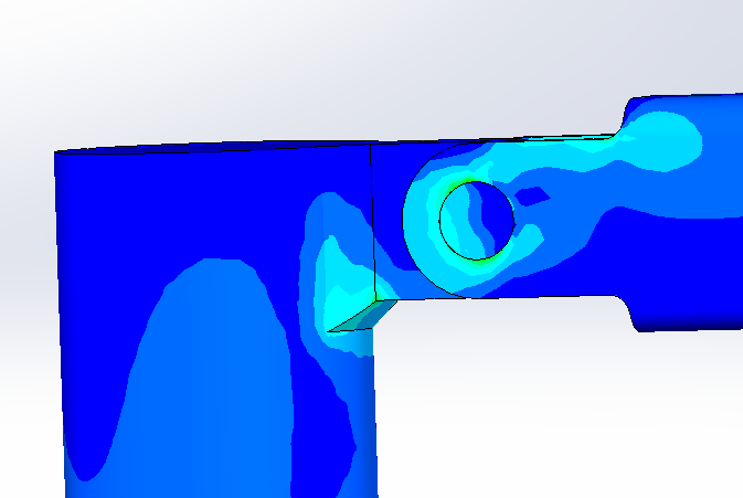
- Interpret the stress to see which way the stress should flow through the pin. In the figure below, the pin has three nearly vertical lines. We would initially make our pin have the contact surface be perpendicular with this which is about 15° from horizontal. (Using our forces in Step 1 will also give us an idea of the angle needed). We will need to have the contact at the bottom on the jib arm clevis and top on the vertical tube clevis. (If I remove the pin, the jib arm would go up and to the right.)
- Model a pin with reliefs in it and orient accordingly.
- Run the analysis and adjust the pin accordingly.
Modeling the Pin
Similar to the cylinder, we will model the pin with reliefs in it so that it only contacts where it should according to your hand calculations.
1. Extrude the Pin
Make a simple cylindrical midplane extrusion for the nominal diameter of the pin and set the length to the effective length of the joint (no extra length for clearance). The midplane extrusion will ease the rest of the process and usually give a great way to mate the pin in place.
2. Add a Center Relief
Make a sketch on the midplane of the pin two concentric circles 1/16″ (1.6mm) apart. Add the lines shown and make them coincident to the center of the circle. Add a 90° dimension and make one set of points vertical. This causes the cut to be symmetric about the top plane. This will help us in mating the pin in the model.

3. Add the Outer Relief and Mirror
Make a similar cut as above from the end of the pin to the surface of the center relief. This cut should be 180° from the center relief cut. Once complete, mirror it about the midplane.

4. Inserting the Pin into the Model
After the modeling is complete, you can replace the existing pin with it. We will mate it at 15° from horizontal as indicated from the stress lines. Remove any left over contact sets and run the analysis.


You can see here that the stresses are much higher than the solution with contacts. This is because the pin is installed at the wrong angle. Don’t get too caught up in this because we aren’t looking for accuracy in this location anyway.
However to illustrate what an acceptable angle is, I have rotated the pin to 60° below horizontal and rerun.

Once again, we are not looking for accuracy in this joint. If you need accuracy, use a contact set. Also, don’t spend a lot of time trying to figure out what the “right” angle is. On short run models, under 10 minutes, you have eaten up any time savings by screwing with the pin angle more than once.
In Summary
FEA run times are often excessive and we should be looking for ways to simplify our modeling. Modeling cylinders and sometimes pins as weldment components instead of pivoting items needing contact sets, FEA run time can be minimized significantly.
| Model | Run Time | Reduction |
| Contact Sets on Pin and Cylinder | 165 s | – |
| Bonded Cylinder Contact Set on Pin | 91 s | 44.8% |
| Pin and Cylinder Bonded | 24 s | 85.4% |
By using these two concepts, we have been able to reduce the FEA run time from 192 seconds to 24 seconds. What a time savings!