

Reading a hydraulic schematic for the first time is a daunting and confusing thing. There are so many symbols to identify and lines to keep track of. I hope to impart to you a systematic approach to reading a hydraulic schematic.
The basic steps to reading a hydraulic schematic are:
- Identifying line types
- Identify if lines cross with or without connecting
- Identify the components
- Identify the flow path at a de-energized state
- Determine what happens as each valve is moved
- Activate multiple valves at a time to see if there are unintentional consequences.
So, the good thing about this is that while we are using hydraulics, a lot of this is directly related to pneumatics. Pneumatics will have a few extra components that we don’t use in hydraulics such as oilers, air dryers and Venturi Vacuums, but they are similar.
Let’s get started.
1. Identifying the line types
In a hydraulic schematic, each line type has a unique meaning. In addition, colors can be added to indicate purpose of the line. In the figure below, all of the basic line types are shown. The basic line is a solid line that represents a working pressure hose or tube. The red line indicates pressure and the blue line indicates a low-pressure return line. In this case, it is a suction line for the pump. The teal and green dashed lines are called pilot lines or drain lines depending on their purpose. Both lines shown here are pilot lines. A pilot line is a high-pressure line with low flow (1/4 gpm). A drain line is the opposite, a low-pressure line with higher flow. Finally, the yellow center line around some symbols is an enclosure line or bounding box. The purpose of this line is to show that all the components within are contained in one valve block or manifold. The purpose of this is to simplify real-world identification.
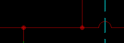
2. Identify if lines cross with or without connecting
There is a little controversy with this one. In the early days, if two lines crossed, they were connected. If you didn’t want the lines connected, you would draw a hump across one line adding some drama to the schematic. Well, as more and more people heeded to the advice of the Black Eyed Peas saying the, “you don’t need no drama, drama, no, no drama, drama” the standards were changed. Now, you will need a dot to indicate crossed lines that are joined. If there is no dot, there is no connection. Who knew that the Black Eyed Peas were actually singing about hydraulic schematics? Ok, so the song obviously doesn’t have anything to do with hydraulics. In all honesty, the change came because it was far easier to add a dot than to erase lines and make the hump. Personally, I like adding the hump and using the dot. With this, there is no guessing as to what my intent was. A dot means that they are connected and a hump means they aren’t. Very clear to anyone reading the schematic. The figure below represents this concept.
3. Identify the components
Identifying the components is the key to the whole process. If you understand what each component does, you can see more clearly how they will work together. Other lists of hydraulic components usually just tell you what it is. This list will be different in that I will give insight into the function and pros and cons of using each. Understand that this is in no way an exhaustive list and new components are being developed all the time.
Flow Reducers
In every hydraulic system, you will have one function that requires full flow and another that needs much less flow. This is where flow reducers come in. The most basic type is an orifice which is a hole drilled in what would otherwise be a plug. As you can imagine, there is a fixed amount of oil that can be pushed through the hole.
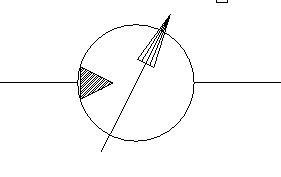
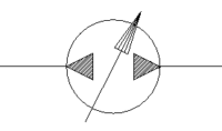
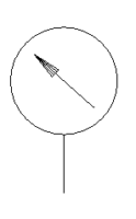
A needle valve is what you would want if you needed to adjust the flow. (Note the arrow for adjustment.) These components are good if you just need to limit the flow but don’t really care if you have bi-directional flow or overrunning loads. Let me explain. If you are using a needle valve to limit the speed of a hydraulic motor, in theory you could put the valve on one port only. However, you will notice that you will get vastly better performance rotating the motor one way. Going the other way, you will see jerks in rotation. The reason for this is friction in the motor and the system it is driving. Granted, the average speed was what was desired, but the performance was not. I would now like to describe two new terms, metering in and metering out. Metering out is the method of metering the fluid coming out of a valve and going to the motor. This will give you poor performance because we are at the motor’s mercy for handling friction. Sometimes we may turn the motor at 500 psi, sometimes at 1200 psi. Who’s to say? Metering in is the better solution. Metering in (into the valve that is) forces the outlet of the motor to maintain a constant pressure. The inlet pressure can still fluctuate wildly but the motor speed will remain steady. To accomplish a meter in on both sides of the motor, we can’t use a needle valve anymore because the flow will be metered twice.
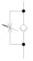
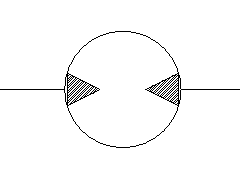
Flow control valves were developed to have unrestricted flow out of the valve and metered flow back into the valve. The check valve is what allows unrestricted or ‘free flow’. (Free flow is from bottom to top). These come in both adjustable and non-adjustable configurations. One final thought is that these valves will build lots of heat especially with positive displacement pumps. You can minimize this by having a compensated flow control valve that will send bypassed fluid to tank instead of building up pressure until the relief valve kicks in.
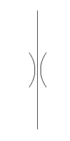
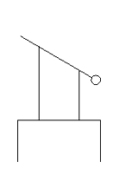
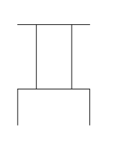
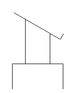
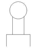
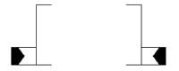
Reservoirs (or Tanks)

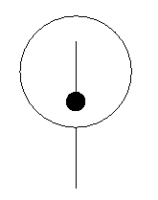
There are two types of tank schematics: pressurized and unpressurized. Unpressurized is definitely most prevalent in the market. One can infer that the pressurized tank is the one that is enclosed.
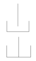
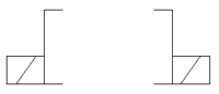
With a reservoir, you can also indicate if you want oil to be returned above (top) or below (bottom) the oil level in the tank. I’ll be honest, I don’t know why you would want oil returned above the oil level. Doing so tends to add air to the fluid (think about a fish tank). If too much air gets into the suction line, you can potentially make your incompressible fluid a little more compressible which leads to poor performance. The irony is that I almost always see the schematic indicate to return the oil above the oil level.
Learn More:
4 Important Components for Every Hydraulic System and Why
A Quick Guide to the Basics of Hydraulic Relief Valves and Filters
A Simple Guide to Hydraulic Pumps and Reservoirs
Filters and Heat Management
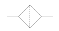
All oil should be maintained by the system and filtration is a must. It is a diamond with a dashed line indicating that the fluid must flow through a screen of some kind. Many filters will also have a spring loaded check valve in parallel so that if the filter is clogged, oil will bypass through the check valve.
Maintaining oil temperature is also essential. If the system is intended to be used in cold climates, oil heaters (right) are a must. The arrows point into the symbol indicating the direction of heat flow.
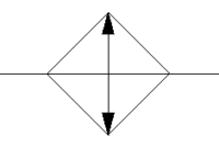
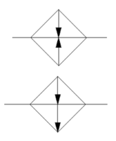
A heat exchanger (above left) is used to reject heat from the system and the arrows point out. There are also temperature controlling systems that can either reject or add heat. This is represented with one arrow pointing in and one pointing out. It is important to note that these can be turned on and off as needed so that only one or none is active.
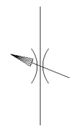
Pumps and Motors
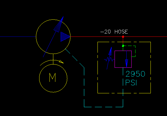
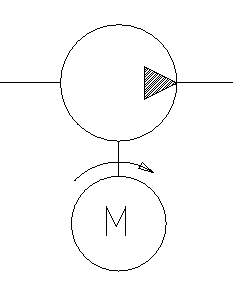
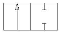
Pumps and motors are probably the most easily identifiable components on a schematic. This is always the first component I look for because this is where the magic starts. Pumps will have the arrows pointing out indicating that fluid energy is flowing out from the pump. Hydraulic motors have the arrows pointing in.
If a pump is driven by an electric motor, it can be shown connected to it. The direction on rotation can be shown. Remember that the rotation direction shown here is clockwise when looking at the pump shaft, not the motor shaft. Both pumps and motors can be fixed displacement or variable displacement.
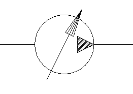
One cool thing is that you can actually have bi-directional pumps and motors. We can see why you would want a bi-directional motor, but why a pump? Bi-directional pumps are generally paired directly with a motor in a closed hydraulic system. Instead of returning the used oil to the reservoir, it goes directly back to the pump. There are a lot of winch applications that use this type of system.
How to Determine if your Hydraulic Pump is Working Properly
The Best Guide to Two Stage Hydraulic Pumps
Watch Out for Heat! – Overheating: The Hidden Danger in Pressure Compensated Hydraulics
Good Advice for Using a Hydraulic Motor as a Pump?
How to Minimize Shock in a Closed Center Hydraulic System
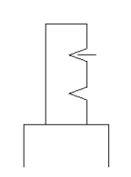
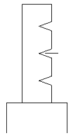
Accumulators

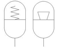
Accumulators are devices that store pressurized oil. This is prominent in systems that have a very high peak horsepower, but the duty cycle of that is low. A good example of this is the ‘Top Thrill Dragster’ roller coaster at Cedar Point. (image courtesy of daveynin on Flickr). Lots of power is used in a few seconds to launch this car over the hill. However, the cars only launch every 60 to 120 seconds so that whole time in between can be used to produce energy and store it in accumulators until needed. Accumulators come in two types, spring loaded (indicated by a spring) and gas charged.
Cylinders
Cylinders are linear actuators that can produce large forces in small volumes.
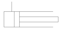
There are generally three types represented in a schematic. A single acting cylinder is one where hydraulic oil is only supplied to one side (usually the bore) and either gravity or springs make it return. A bottle jack is a good example of this.
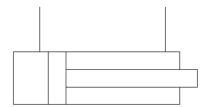
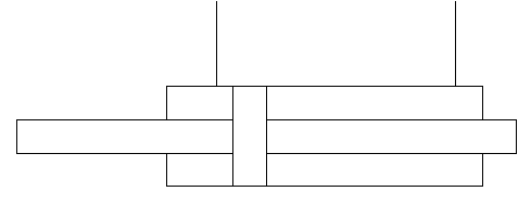
Double acting cylinders are the most common, and pressure can be applied to either side to make the cylinder extend or retract. Since the extend area and retract area a different on a double acting cylinder, you may get undesired performance. Double rodded cylinders are an answer to this because the area is the same on each side of the piston.
For Further Reading:
Ultimate Hydraulic or Pneumatic Cylinder Calculator
6 Secrets for Synchronizing Cylinders
Easy Guide to Laying Out a Cylinder for Articulation Applications
Don’t Make These Mistakes With Ram Cylinders, I did…
How to Determine a Cylinder Bore Diameter Without Disassembly
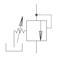
Pressure Controlling Valves
Controlling pressure is essential in all hydraulic systems. Every system must have a relief valve to protect hydraulic and mechanical components. In this schematic symbol, the pressurized fluid is on the top side of the valve. If the pressure is high enough to overcome the spring, the arrow will shift over and oil will flow through in this case, to the reservoir.
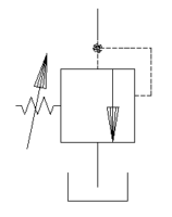
However, we can change the ports a little and get different performance. Instead of having the output flow go to the reservoir, we can make it power something else say a motor. This is a sequence valve. If I have a hydraulic drill press, when flow is turned on to the top side, perhaps I have a clamp that I want to engage first. I could connect the cylinder to the top side line and the cylinder would clamp in order to build up pressure. It is only after enough pressure is built that the motor would turn.
A pressure reducing valve is also an important hydraulic component. A recent system I designed had one side operating at 3000 psi and another side operating at 400 psi. I incorporated a pressure reducing/relieving valve where the left port had the full system pressure of 3000 psi. The right port was set to give me reduced pressure of 400 psi. If pressure in that line rose, it would relieve that pressure to tank through the bottom port.
Load Holding Valves
Any load holding valve will be based on some form of a check valve. A check valve will allow flow to move easily in one direction, but not in the other. This is great….if we want to hold the load forever. Often that is not the case, so we need a method of bypassing flow.
The pilot to open check valve, commonly referred to as a PO Check, is used to unseat the poppet. (Spoiler alert: check valves don’t use balls because they are super difficult to make and don’t seal well. A poppet is a segment of a cone shape that seals much better.) Generally, if a directional valve uses work port A to lift a load, work port B is used to lower the load and unseat the PO check valve.
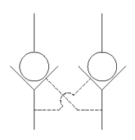
If both directions need to be locked, you can use a double PO check valve. This is a manifold that combines two PO check valves and simplifies the external plumbing needed by incorporating the cross pilot lines.
Must Read: Drift:Why You Should Never Hold Loads with Directional Valves
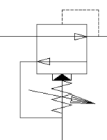
Counterbalance Valves
There is one major downside to using a PO check valve: Temperature. If your need is to have load holding in both directions, a PO check can actually create extremely large pressures. Imagine the situation of setting up a device under load early in the morning. The load and position don’t change all day, but the temperature gets 30° to 40° warmer. The oil will expand creating pressures that can exceed the motor or cylinder’s capabilities. It is a bad situation. Luckily, a counterbalance valve comes to our rescue. A counterbalance valve allows free flow into the motor or cylinder through a check valve, but there is a specialized relief valve on the way out. If the pressure in the cylinder is too high, it will relieve pressure (port 2 to 1) until the valve closes. There is also a pilot port (port 3) to open a path for return oil flow.
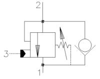
The cool thing and the thing that will cause a lot of headaches is that you can tune the performance of the system by taking advantage of the metering in functionality available. This is controlled by two things: pilot ratio and flow capacity. I don’t have enough time to get into it now, so we will save that for another article. Counterbalance valves are available in single or dual configurations.

If holding your load still is important in your design, you need to use a load holding valve. Do not use a Directional Control Valve to do this task!
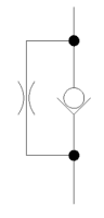
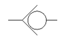
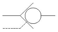
Shuttle Valves
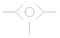
Shuttle valves are logic elements that allow two (or more) things to signal something else. A shuttle valve is basically two check valves with only one ball (yes, poppet, I know). The higher pressure will force the poppet to close the lower pressure side and send pressure and/or flow to the perpendicular path. Compensated valves are a good example of this, where each valve section will send the compensator pressure back to the pump to determine how much pressure is needed. The pressures are compared to each other using shuttle valves and the highest pressure wins.
Directional Control Valves
Directional control valves are the pillar of hydraulics. These allow fluids to change direction and flow paths. These valves are specified by their positions and ways. Positions are the number of discrete configurations of the valve. Ways are the number of ports the valve has. A two position, two way valve would be used to turn on and off flow.
A three position, three way valve could be used to fill and discharge an accumulator. You would want high pressure oil to fill and then connect to a low pressure path to discharge.
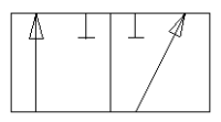
A two position four way valve can change the direction of fluid where you could change the direction on a motor or cylinder. These valves can have a soft shift option (left) where a phantom third position allows for a smooth transition as indicated by the dashed lines between positions. This extra position ties all the ports together to neutralize pressure and minimize the momentum effects when reversing flow.
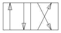
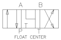
A three position four way valve offers an off position so that the system can rest. This center position can come in numerous configurations that can satisfy almost any requirements. Please read my article on directional control valves for more information.
Other Reading
Avoid Using Tandem Center Valves in Series
Connecting Multiple Open Center Valves Using Power Beyond
Directional Control Valves – What Every Engineer Should Know
A Quick Guide to the Basics of Hydraulic Relief Valves and Filters
Valve Actuation
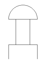
All positional valves need to be actuated to perform a function. We will start with mechanical actuations. From left to right they are: push button, mechanical action, lever, foot switch and mechanical switch. With the exception of the lever and push button, these are getting harder and harder to find. Electronics has improved so much in the last twenty years that it is far easier and less expensive to run wires to electrical sensors than hoses to hydraulic components.
Pilot pressure and electric actuation are the dominant forces in the market and will be for some time. Electronic control systems allow for the precise application for pilot actuation (left), where low pressure shifts the valve, and electro-proportional actuation. The right schematic symbol is for a solenoid operation. A solenoid is a non-proportional signal that fully moves the valve. For proportional operation, other methods are used and an arrow would be drawn through the symbol.
Many valves are biased to one direction or the center position. Springs are the method of accomplishing this. With all these controls, you do not need to have actuation on both sides.

If you don’t want the valve to move when deactivated, you can add detents (center and right) to make sure the valve stays in the same location. Detents are usually a spring loaded ball (yes, actual ball) that will lock into a groove in the valve spool.
Miscellanous Components
There are a few components that don’t fit into any specific categories that I would like to share now. Pressure gauges are the most common. They will give the pressure of the line where they are installed. Be aware of the effects of flow in the system. I recently had to relocate a pressure gauge because the pressure drop due to flow was giving me false readings. I moved the gauge to the component I was interested in and the false readings stopped.
Temperature indicators look like thermometers. They can be placed throughout the system like pressure gauges, but many designs just monitor the reservoir temperature using a sight gauge. A sight gauge (not shown) will indicate the oil level and usually the temperature in the reservoir.
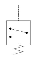
Pressure switches are switches that change state when a certain pressure is reached. Please note that hysteresis is a problem with these so if a switch is set at 400 psi when rising, it may not switch off until 350 psi when falling. They can come in Normally Open and Normally Closed configurations and fixed and variable pressure settings.
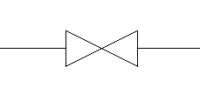
The last symbol is a manual shutoff valve. These are generally low pressure devices and are used on the suction and return lines near the reservoir to allow for easy changing of the oil and filter. Be sure to keep these open. Bad things can happen otherwise.
Wow, there sure are a lot of symbols, and as I mentioned, this list is not exhaustive. Hopefully, you can already begin to see how some of these components will work together like how a directional control valve will control a cylinder.
4. Identify the flow path at a de-energized state
As I mentioned, looking for the pump(s) in a schematic is where I start. Trace lines outward from the pump until you hit a closed valve. Repeat until you are back at the reservoir or run out of paths. I then look to make sure that the system has the other three critical components. Once satisfied that the four components are there and correct, I will start to look at the de-energized state. When all components are de-enegrized, is flow allowed to return to tank or does it build system pressure or is it somewhere in between? I usually trace this out with a highlighter. If I have a fixed displacement pump, I want that oil returning to tank at near zero pressure. If I have a variable displacement pump, all the flow paths should be blocked and our compensator pressure set at least 200 psi less than the relief valve.
In the Example 1 (below), the fluid with flow through the first work section comes out through work port A and into the manifold from the right. At this point it is stopped at all seven valves. It also goes through the pressure limiter and is stopped at the directional control valve. This system allows pressure to build fully and indicates that we need a variable displacement, pressure compensated pump which we have.
5. Determine what happens as each valve is moved
Now that we have our de-energized state identified, we should then energize components one by one. (Sometimes there may be an enabler that needs to be energized as well. This is the case with Example 2.) Keep track in each section for what happens to pressure and flow and what the desired outcome is.
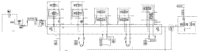
Section 1 of the manifold will reduce the flow (meter out) by activating the top valve to pilot open the larger valve below it. This will then send flow out port B but not before sending it through a flow control valve.
If we activate Section 2 to pressurize the A port, we should see the top valve activate the larger valve below it. This flow will go out port A and pressurize the pilot port on the counterbalance valve. Once outside the manifold there are two flow control valves that will control the motion of the motor by metering the fluid in. There is also a pressure switch that will indicate if the motor has stalled (we are only looking for the signal when the B port is energized). The other three ports on the valve are similar so I won’t go into detail here.
The two valves on the right beyond the pressure reducing valve control a cylinder. If the right coil is activated on the left most valve, the cylinder will retract slowly by gravity as metered by the needle valve. However, if the valve on the right is activated, the needle valve is bypassed and the cylinder will lower much faster.
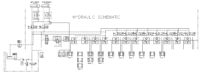
As mentioned, this schematic has a positive displacement pump and needs to have an unloader valve closed before any motion can happen. This is done by energizing S7 which must be done with any other solenoid.
If we energize S1 and/or S3, we will be able to retract the left and/or right extension cylinder. However, when we activate S2 and/or S4, we do not want to extend before all the cylinders on the bottom have been retracted so that we avoid collision. To do this, we use a shuttle valve so that the flow from S2 and S4 do not contaminate each other. The flow then goes on to apply pressure to a counterbalance valve and retract all the cylinders.
Note the center position of the directional control valve (3 pos. / 4 way) activated by S5 and S6. The P and A ports are blocked, but the B and T ports are connected. This is done specifically so that we have a path to get the oil out of the cylinders. Once all of those cylinders have retracted, only then will there be enough pressure to overcome the sequence valve and extend the extension cylinder(s).
Energizing S5 will retract all of the cylinders as S2 and S4 will, but it will not extend the extension cylinders because of the shuttle valve.
When S6 is energized, we will start extending the cylinders in a prescribed way. (Note that we did not care how the cylinders retracted.) The flow will come out of work port B through a flow control valve. Since we have a positive displacement pump, we didn’t want to have the remaining oil bypassed over the relief valve. We did this by using a compensated flow control so that our extra flow would go right to tank (port 2) at a much reduced pressure. The metered fluid (port 3) then goes on to a counterbalance valve where it will free flow through the check valve.
At this point, Group 1 is activated. Group 1 is two horizontal clamping cylinders and will extend until 300 psi is built up. At that point, Group 2 is activated where four vertical and two horizontal clamps are actuated. At 400 psi Group 3 is activated and so on until we get to Group 6. When group 6 is activated, if Solenoid S8 is not active, it will extend the cylinder. If S8 is active, the section will not press and it prevents flow from reaching anymore sections. S8 is triggered by a proximity switch that detects how long the work piece is. If there is material there, S8 will disable and the section will press.
6. Activate multiple valves at a time to see if there are unintentional consequences.
Unintended consequences are very difficult to see and predict. The real challenge here is to learn from these so you don’t make them twice. One common occurence is energizing both sides of a directional valve. Usually there is no damage done, but your control system should be configured to eliminate this hazard. If using relay logic, you can have one relay to turn on power to a valve and another to select the direction.
In Example 1, there was an unintended consequence when I activated Section 1 and the B port of Section 2. It glares at me now, but before it was very difficult to see until the system was built. On the motor, I have flow control valves to control the speed of the motor. However, I want to limit the speed of the motor before stopping it (the location of stopping is important.) I do this by activating Section 1 about a foot before the stop point thus reducing the speed. However, the reduced flow is lower than that of the meter in flow control. The result is a low flow metered out condition and my motor jumps to its stopping position. We are taking steps to correct this.
In Example 2, the two position, three way valves should have been configured so that the positions were opposite of each other. The reason for this is to prevent damage to the machine. If a wire is broken to one of the solenoids, extra sections will press and may cause potential damage to the machine. To minimize this risk, we added extra protection to the wires, ran larger gauge wires than needed and added inspection of the wires to the monthly preventative maintenance checklist.
Conclusion
Reading schematics is a very scary thing, but remember to relax, you are smart and mommy and daddy love you very much. You got this! Just work through it slowly and don’t be too quick to ask a question. When doing work like this, I often wait until I have a good series of questions before I ask for help. This way I will have spent more time working through the schematic so that my questions are thorough and won’t waste a coworker’s time.
Once you master the skill of reading prints, you will be able to critique and create your own systems. Remember to use a systematic approach and always have your work checked before you purchase components. So, grab your highlighters and find some schematics to analyze!
Great Lesson, Thank You