When working with hydraulics, the ability to troubleshoot common problems is critical. The first step in troubleshooting any hydraulic system is to ensure that the pump is working correctly. Proper assurance that the pump works will help isolate the problem. This requires plotting a pressure vs flow chart even if only in your mind.
Creating the plot is easy while eliminating all other sources of the problem is not. Most likely we notice the failure when it does not put out enough pressure.
Diagnosing a Pump Failure
As mentioned, the best way to figure out if a pump has or is in the process of failing is to create a plot of pressure vs flow. If our plot can produce both pressure and flow, our pump is probably good.
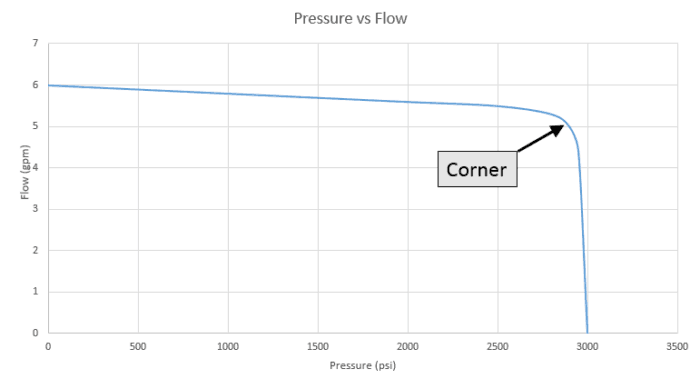
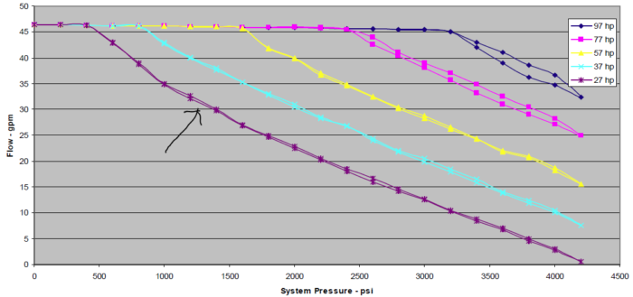
The chart above is typical of what we would see from both a fixed or variable displacement pump. A variable displacement pump with torque limiting would have a negative slope line where the torque limiter is engaged. (Below)
Equipment Needed
The first thing that you need is a flow meter test kit that has a flow meter, pressure gauge and needle valve. You can find these for as little as $500. You will also need some wrenches to take apart fittings, rags and oil pans. You are going to get oily! (Yea)
Testing Fixed Displacement Pumps
On a fixed displacement pump, we will be checking the pump and the main (system) relief valve at the same time. You should never run a pressure test on a fixed displacement pump without a relief valve installed. You can do serious damage to your equipment.
Testing Variable Displacement Pumps
Variable Displacement pumps are a little different. They all have an internal compensator and in most cases a remote compensator. Mobile equipment may also have load sensing.
For testing purposes, we will want to connect the load sense line to the pressure line and block any down stream functions. Also, set the remote compensator to the lowest pressure possible (usually all the way out). The remote compensator is almost always a simple cartridge style relief valve.
Test Procedure
- Disconnect all components / hoses from the pump discharge port except for the system relief valve on a fixed displacement pump.
- Connect the test flow meter to the discharge of the pump.
- Open the flow control valve all the way on the test meter.
- Start the motor or engine that powers the hydraulic pump.
- Check for leaks.
- Record the pressure and flow.
- Slowly shut the flow control valve which will increase the pressure.
- Record the pressure and flow values at roughly 500 psi increments.
- As you get close to system pressure, take more readings at smaller increments (maybe as little as 50 psi).
- Plot these values on a chart and compare to the charts above.
Interpreting the Results
If the tested values look like the charts above, your pump and relief valve work properly. Disconnect the flow test meter and reconnect the rest of the system. Your problem is located somewhere else in the system.
If your test does not look like the charts above, the pump can still be good. In both cases, there is a relief valve in the system. The variable displacement pump also has a compensator that can be causing issues.
Checking the Relief Valve
Most relief valves are cartridge style with two advantages; they are easy to remove to flush out contaminates and they are easy to replace.
Having your oil pan ready, unscrew the relief valve cartridge from the manifold (slowly). Once out, allow the hydraulic oil to clear out the manifold. Also inspect the cartridge for signs of contamination. If everything looks clean, reassemble and repeat the test.
Still Not Working?
If the test is still unsuccessful, replace the relief valve and repeat the test. If it still not producing pressure, replace the fixed displacement pump. It is bad.
With a variable displacement pump, we now need to isolate the problem to the pump or internal compensator. Thus far, we have avoided messing with the internal compensator because it is usually mounted on a pump submerged in hydraulic oil.
First we will eliminate the remote compensator completely as the problem by capping off the flow to it. Start the motor and look for rise in the system pressure. If it does not increase, we will shift our focus to the internal compensator. Reattach the remote compensator.
This is where things get messy if you have a submerged pump.
Locate the compensator on the pump which is the large block labeled “Rev B” on the photo below. Most times, you can clean out the compensator yourself. Find the assembly instructions or parts breakdown from the manufacturer if possible.
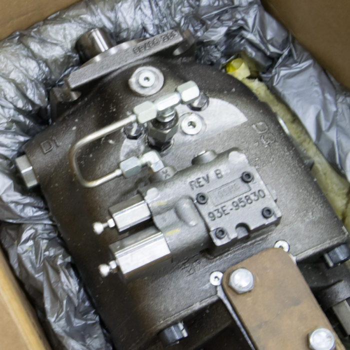
If not, disassemble one part at a time and keep good records. I usually take a picture each time I remove a part.
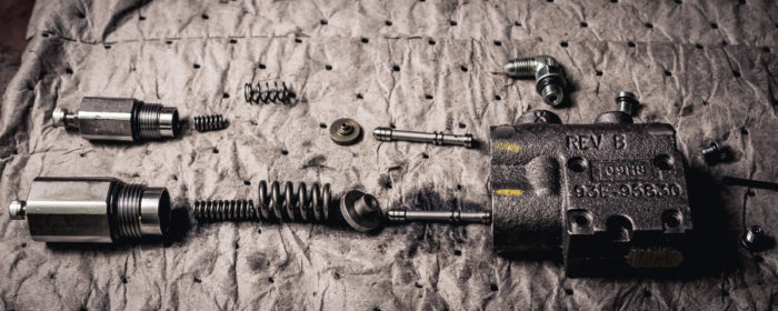
Look for contamination in the cavities and flush with hydraulic oil to remove loose debris. Do not use sharp tools to clean the components because scratches can prevent the components from performing correctly.
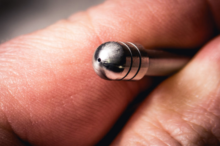
In the case above, there was a small amount of debris inside the small hole shown below. I gently pushed it loose with a small needle and blow it out with compressed air.
Once the compensator components are clean, reassemble and install on the pump. Prime the pump according to the manufacturer’s recommendations.
Once primed, Reattach the remote compensator and run the test again. If the pump still does not produce pressure, your pump is bad and needs to be rebuilt or replaced.
What Causes a Pump to Fail?
Contamination and Over Pressurization
The main cause of pump failures is contamination. Debris that is in the tank or ingested from hydraulic cylinders can drastically shorten the life of a pump.
For variable displacement pumps, contamination seems to clog the compensator first. It has many small cavities that can get clogged easily. I recently worked on a piston pump where the shaft coupler to the motor shredded and parts of it were clogged in the compensator.
Over pressurizing the pump is the second most common reason pumps go bad. Make sure that your relief valve is installed properly and
‘Shelling Out’
‘Shelling out’ of a pump is a term used to describe a pump being run dry (without oil). Pumps are designed with very tight tolerances between moving parts. Common gaps are 0.0002 in (5 nm) and round surfaces are usually honed for accuracy.
The reason for this is that every gap will leak oil. The larger the gap, the more oil that is leaked. You can imagine that very small gaps are desireable for top perfromance.
The problem comes when a pump or motor are run dry. The gears in a gear pump are usually steel and the housing around it is some form of brass. If there isn’t any lubrication between the two, the brass will wear out quickly. Within seconds! As larger gaps are produced, you will never get full pressure out of the pump again.
How to We Prevent the Pump from Failing?
To prevent over pressurization and contamination, proper relief valves and filter are required. I recommend these two other articles for proper relief valves and oil filtering.
Preventing Shelling
To prevent shelling out a pump, I recommend reading the manufacturer’s recommendation for priming a pump. For a submerged pump, this might be opening a case drain port on the top of the pump and let oil flow in. (You’re going to get slimy.) Other pumps may require pouring oil into the ports and case drain.
If your pump has shelled out, there is contamination all though out the system. If you have a high pressure filter installed, you’re okay. If not, you will need to flush the system at low pressure. The suction filter or return filter should prevent this contamination from being reintroduced into the system.
Conclusions
After reading this article, you should be able to diagnose a pump failure and know key places to look for pressure issues. You should also be able to prevent the common causes of pump failure.

