

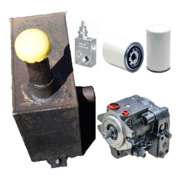
For any hydraulic system, there are four basic components that are needed. They are:
- Reservoir or tank (A place to store low pressure fluid which is fed into a hydraulic pump).
- Hydraulic pump (These come in various shapes and sizes but they need to be protected by a relief valve).
- Relief valve (This ensures that the pressure does not build passed the design pressure).
- Filter (Necessary for the components to use clean hydraulic fluid).
The field of hydraulics is vast and can be complicated. Since none of us have a coal power plant in our garage, we can treat hydraulics similar to electricity in that you can have the power generation station far away from where the power is needed. The power is transmitted via wires (sometimes called electron hoses) and the power eventually does work, like heat something or make a motor turn. Hydraulics also had a remote power unit and the power is transmitted using hydraulic fluid via hoses. With hydraulics, the sky is the limit as for powering actuators like cylinders, motors and fans. You just have to run hoses there.. Add in control systems and every hydraulic machine is unique.
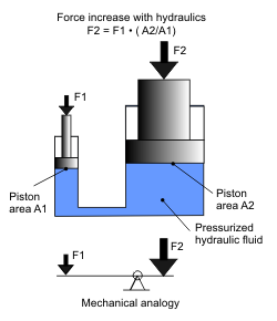
Hydraulics is largely governed by the equation Force = Pressure x Area. If I stand on top of a cylinder, my weight divided by the area of the cylinder would give us a pressure. Now imagine that the cylinder is connected to a larger cylinder using a hose. Since the area is greater, I could hold up a heavier item.
A good mechanical similarity is a lever with the fulcrum in the center. If you have unequal loads, you will need unequal lengths to make the lever horizontal. But this is never the case in reality. If the pressures are unequal like if I had lost a few pounds, I would notice that I would start going up. If I gain some weight, I would go down.
There is now a velocity function of the hydraulic system that needs to be analyzed. This is where hydraulics gets interesting. However, instead of me standing on a cylinder, we generally replace that silly notion with a rotary pump.
1. Hydraulic Reservoirs
To begin let’s talk about what a reservoir is and the general makeup of how it works. In our application a reservoir is simply a large container of oil at low pressure. Often times this is atmospheric pressure, but not always. An example of this is your car’s fuel system. The reservoir, gas tank, functions at an elevated pressure. This increases power and fuel efficiency of the engine. If the tank is not able to build pressure, it throws an error code and costs you money.

The biggest question to answer with a reservoir is “how big does it need to be?” The general rule of thumb is to have three times greater the amount of storage than your flow rate. Basically, if I have a ten gallon per minute flow rate then I will need at least 30 gallons in oil storage.
A secondary function of a reservoir is to dissipate heat. The more oil I have in the reservoir, the more heat it can reject from the system. While this is still a good rule, it is not an absolute. Quite simply, it does not take into account what type of pump or what work is being done. For example, my log splitter has an 11 gallon per minute flow rate while operating at free flow with a 2-gallon reservoir which does not meet this criteria. But it isn’t causing me any problems. Why?
First we need to revisit how energy works. All energy that is not doing work eventually becomes heat. This is the second law of thermodynamics. What we want to be doing with our hydraulic system is design it so that the vast majority of the power produced is doing work. This means that very little heat is produced; not to mention that we are saving in energy costs.
With the log splitter, we have two things that work in our favor to reduce heat. First, I am not building up much heat or pressure because for most of the cycle, we are just pushing a cylinder in and out under no load. Second, when I do create pressure, it is when contacting the piece and pushing through the knife. This is really the only time I can produce more heat generated by the system. At this point my flow rate decreases from 11 gallons per minute down to 1 ½ or 2 which gives roughly a 1:1 ratio and allows the flow rate to be nearly equal to the capacity of the tank. In this case both the two stage pump and a well-defined duty cycle allow us to decrease the size of the tank.
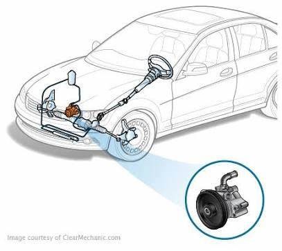
Some reasons to have a smaller reservoir are special limitations or the desire to limit the amount of fluid spills. The automotive industry is a center of expertise on how to design high flow systems with really small reservoirs. For example, it is not uncommon to see a 1 L reservoir with a 6 L/min flow rate on a power steering system. If I have a lot of heat generation but cannot increase the reservoir size, a solution would be to add a heat exchanger. A heat exchanger looks much like your car’s radiator where air is pulled across cooling fins using a fan. This is a simpler and cheaper option that allows control of the fluid temperature much more efficiently than adding oil and hoping it is a large enough heat sync to work. You may want to also add a low fluid limit switch to protect the pump from running without fluid.
The main reason to argue for a larger reservoir is if you need to displace a lot of oil. You can displace a lot of oil when you have large cylinders, especially ram cylinders (rod area is less than 50% of bore area) or lots of cylinders. For example, I just designed a system where two very long ram cylinders were to be powered. When these are fully extended the differential in oil in cylinder is 45 gallons. If I have a 30-gallon tank I will run out of oil about halfway through and not be able to fully extend the cylinders without bleeding the pump dry. Even a reservoir that is 80 or 90 gallons may not be adequate: we should not be designing our suction lines to be directly on the bottom of the tank so we will lose a few inches of height and usable oil. In the case of submerged pumps, we may need to leave extra oil so that the pump can self-prime. This is usually accomplished by having a very tiny hole in the top of the suction line to let air bleed out. If the reservoir isn’t large enough, you can uncover this hole and allow air back into the system. Having air in a hydraulic system causes poor performance at best and failed components, especially pumps, at worst. In this example, I am going to need a much larger tank to fully extend the cylinders and operate the system efficiently. When all is said and done, this system will probably have a 150 gallon reservoir with a 12:1 ratio of size to flow.
If you operate on slopes or deal with large swings of ambient temperature, you will need a larger tank. Hydraulic oil does expand and contract with heat so you need to account for the coldest of days all the way up to 180°F. When dealing with operation on a slope, you probably have a mobile application which means that the oil will slosh around routinely. Extra capacity will ensure that the pump will not run out of oil and it won’t leak out of the fill cap.
Some thoughts on Reservoir Shape
After considering the capacity size of the reservoir, it is important to factor in the physical shape. Personally, I prefer a taller shaped reservoir for mobile applications because it will allow the oil level to remain well above the suction port while tilting the tank. To contrast this, if I have a wide and short tank, the tilting may not allow oil to fill one end or the other depending on where I locate the suction port. In this case, if I am traveling downhill and the section port is located at the top there may not be any oil covering that area at all. Additionally, if it is not a very tall tank there is the risk of spilling oil out of the top of it. For these reasons I prefer a taller tank with a narrow base.
Main Components of a Reservoir
Now let’s take a look at the several main components of a reservoir.
Drainage Port
A major component of every reservoir is drainage. This allows oil to be refreshed and replenished and the tank to be cleaned. Most pre-made or manufactured tanks have a drainage feature built into them. Personally, I like to add a quarter turn ball valve on the tank so I can drain it by connecting a hose and properly shut it off and on without getting covered in oil.
Maintenance and Cleaning
Of course, you will want to be able to keep your tank in great shape in order to extend its usage and life span. In order to do this, it is important to be able to get in there and clean the tank out. The most common way of doing this is to drain the tank, remove the cover and wipe it out with towels. In smaller tanks, the space may just allow cleaning by reaching with your arms into the reservoir or with larger tanks, being able to enter in to clean. Typically, the process requires the removal of a gasket with several bolts in order to gain entry to clean the tank. It is best to replace the gasket at the time of cleaning in order to avoid unnecessary work. I personally like the tank to have clean out access from the top so I do not have to worry about the gasket seal, like you would if it were on the side.
Section Strainer
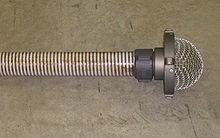
Another important component is the section strainer. This mechanism filters out the big stuff, in your reservoir. It is much like a pasta strainer for cooking. The same concept applies to our section strainer which helps keep major stuff out. An added benefit can be found in using a magnetic strainer which in turn will magnetize all the parts that are steel including the tank itself. When this occurs, all iron parts will adhere to the side of the tank and will not be moved through the system and wreak havoc on everything else. This is one major benefit of using a steel reservoir over plastic or aluminum.
The section line needs to be sized so that the fluid flows slower than 5 foot per second. Anything more than this you can start to cavitate your pump, so you want to keep the line size large and oil flowing very slowly.
Breather Assembly
One of the last components is the breather assembly. This is used to fill your tank and cap it off in order to keep fluid from coming out of it. It functions much like a vehicle’s gas cap with one significant difference in that it is not and should not be pressurized. In a car, as you use up fuel it is replaced with pressurized air coming back. Now, in a hydraulic tank the level is going to fluctuate up and down as the cylinders are extending and retracting,sometimes fast enough that you can feel the air flowing through the breather. In this process, we want to avoid a locked system, like a car, where you have to overcome that air pressure. For this purpose, a breather has a filter in it that allows air to pass through, in and out, and helps prevent contaminates from entering the system. It is important to remember to keep the area clean around the breather before opening and adding oil. The industry I worked in had a lot of chain saws which resulted in a lot of sawdust and wood shavings all around. You never want to open the breather filter and expose those particles to the oil.
2. Pumps
So we can see that there are some limitations in our example above. First, to maintain stability, I’m going to need to stand there forever, which is not my purpose in life. Second, there is only a finite amount of fluid in each cylinder. We can solve both of these problems by replacing the first cylinder with a pump. A pump is simply a device that takes oil, usually from a reservoir, and moves it somewhere else. Take note that a pump’s job is to move oil, not to create pressure. The pressure is a byproduct created outside the pump caused by resistance to fluid flow.
If you add a pressure gauge to your garden hose you can experiment with this. If you turn on the hose with no attachments, you will see that there is very little pressure. This is because there is no resistance. When you start adding attachments or put your thumb over the end. You will see pressure build.
How to determine flow.
Pumps are rated at their maximum displacement. This is the maximum amount of oil that is produced in a single rotation. This is usually specified in cubic inches per revolution (cipr) or cubic centimeters per revolution (ccpr). Flow is simply the pump displacement multiplied by the rotation speed (usually RPM) and then converted to gallons or liters. For example, a 0.19 cipr pump will produce 1.48 gallons per minute (gpm) at 1800 rpm.
Types of Pumps
Hydraulic pumps can be found in three main types:
- Gear pumps
- Vane pumps
- Piston pumps
Gear Pumps
Simply put, gear pumps are positive displacement pumps and are the simplest type you can purchase. Positive displacement means that every time I rotate the shaft there is a fixed amount of oil coming out. In the diagram shown here, oil comes in the bottom and is pressurized by the gears and then moves out the top. The blue gear will spin clockwise.
Vane pumps come in both fixed and variable displacement. The pump contains a shell and an eccentric rotating assembly. There are several spring loaded vanes that run on the shell. The oil is trapped in between two vanes and as the shaft rotates, pressure is able to be built. In the diagram on the right, oil enters from the left, is trapped between vanes, and is expelled on the right. The greater the eccentricity, the larger the pump displacement. If the eccentric distance is fixed, the pump will be positive displacement. If the pump is variable displacement, the output will be conditional on the output pressure. The shell will have a spring pushing on one side and the output pressure will push opposite of that. If the pump is nearing the maximum pressure, that pressure will compress the spring making the eccentricity smaller, if not zero.
A piston pump behaves similarly to a variable speed vane pump, but the internals are completely different. In the diagram below, there are eight pistons (mini cylinders) arranged in a circle. The movable end is attached to a swashplate which pushes and pulls the pistons in and out of the cylinder. The pistons are all attached to the rotating shaft while the swashplate stays fixed. Oil from the inlet flows into the cylinders as the swashplate is extending the pistons. When the swashplate starts to push the pistons back in, this oil is expelled to the outlet.
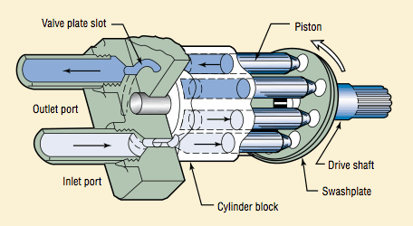
To change the displacement, the angle of the swashplate is changed. The more perpendicular the swashplate is to the shaft, the smaller the flow. Like a vane pump, the displacement will diminish to zero as the outlet pressure nears the maximum pressure.
Cool Options
So there are two ‘cool’ options that can be done with variable displacement pumps. The first is torque limiting or horsepower limiting. Torque limiting monitors the torque on the pump shaft and will minimize the displacement of the pump. Torque limiting allows the pump to output the maximum flow at any pressure which prevents your engine from stalling or a motor from burning up. This is quite common to see in applications where large amounts of fluid flow are needed at low pressures, but when operating at high pressures, the flow can be much less. A log splitter is a great example of this: no pressure is required to move the cutter head to the log, but once contact is made, the speed is reduced.
The other option is load sensing. Load sensing is a system in which information on the load (namely pressure) is sent to the pump so that it can run more efficiently. Let’s say that we had a hydraulic system with one function that needed 5 gpm at 2500 psi to properly operate. However, there is another function that will be used much more often at 3 gpm and 1500 psi. Let’s see how each type of function will perform with a different pump. If we have a gear pump, we will be producing 5 gpm at 2500 psi, using 7.3 hp, but only doing 2.6 hp of work (35% efficient). This is not very efficient at all. If we switch it to a variable displacement piston pump, We will produce 3 gpm, but the pump is only de-stroked at 2500 psi. That is producing 4.4 hp and 59% efficient. While much better, it is still very wasteful.
This is where load sensing comes into play. A load sense system will always try to produce a certain pressure differential between the required load and the pump outlet, called the standby pressure. The standby pressure is generally 250 psi to 400 psi and is always available to the system. For our example, let’s assume that it is 300 psi and when operating the highest loaded function, 2500 psi, it will cause the pump to produce 2800 psi. This seems less efficient, but when we calculate the required horsepower for our function, it is 1800 psi at 3 gpm which is 3.1 hp and 83% efficient.
Another benefit of load sensing is when the system is not being utilized, the pressure drops to the standby pressure (get it, because you are standing by) and no flow is produced. While this is generally a benefit, if you work on mobile equipment in cold areas, it is really difficult to heat the oil up to normal operating temperatures. Tank heaters or other warming devices come in handy here.
3. Relief Valves
A relief valve is the systems main protection from damage. This is not to be confused with damage the system can do, but rather damage to the pump, engine or motor and hoses etc. The relief valve should be mounted as close as possible to the pump and it prevents the pump from being over pressurized. Remember a pump’s job is to create flow. If there is no path for the oil to move, pressure can go to infinity. A relief valve gives the oil a path back to the reservoir. Consequences of improper relief valve application can be:
- Seal leakage
- Cylinders splitting along seam
- Valve splitting
- Hoses rupturing
- Pump shafts shearing
There are two types of relief valves. You’re going to have your pilot operated ones and your direct acting ones. You are never going to have both types in the same system providing the same function. If I have a pilot operated relief valve, I am not going to have a direct acting one and vice versa. Generally speaking, your flow is going to dictate which one you will use. If your flow is reasonable and under 30 gallons per minute, you could probably get a direct acting valve for what you need. If it is over that, you are probably going to have to use a pilot operated valve.

So how do they work? As we can see from the schematic, oil comes out of my pump at high pressure (2750 psi) and will go over to where the work is done. If the pressure starts rising it will branch off and try to flow through each block. Let’s focus on the direct acting valve first. We see that the arrow does not line up with the line coming in. This valve is closed and oil will not go through. But what it does do is send a small trickle of oil over here as a pilot signal (green lines) and starts pushing this block to the left. If there is enough pressure to overcome the force of the spring it’s going to slide over and the oil is going to go back to the tank. The pressure needed to open the valve is based on the spring force. When pressure is reduced, the block will close and oil will stop flowing.
The pilot operated relief is a little bit different. Here we still have the same beginnings with pressure coming to the block and it cannot get through the other side of the valve. As the pilot pressure pushes against the spring, the block starts shifting over. When it does that, it is going to send a small amount of oil (typically about ¼ gpm) not to the reservoir, but to an unloader valve. Now the unloader valve here is sized so that our main pump flow can pass through it. When the unloader valve sees the pilot pressure it will shift the block over and compress the spring. This creates a path to tank for the main pump flow.
You can see that these two types of relief valves do the same thing. Pilot operated relief valves are used for large flows simply because springs have limitations. Due to the size and characteristics of springs, large flow direct acting relief valves don’t have a sharp enough corner. If we replace one valve with two, we can get the characteristics we want.

I just mentioned the corner on a relief valve is not perfect. The plot above is typical of a gear pump with a direct acting relief valve. You can see that the corner is quite rounded and in some cases can really effect the performance of the system. One project I worked on required me to improve the performance in the corner area. We tested multiple valves, oil types and temperatures to see which valve worked the best. One other interesting thing to note on this chart is the gentle slope of fluid loss between 0 psi and 2500 psi. This is caused by internal leakage in the pump. Every pump has moving parts in it and these parts require clearances. Though these clearances are tight, they still allow fluid to flow past them. The greater the pressure the more leakage and less overall flow.
As I mentioned before you are going to either have a direct acting or a pilot unloader you are not going to have both systems in there at the same time.
4. Filters
So the last component that all hydraulic systems must have is a filter. In hydraulics, oil cleanliness is key. We will not go into much detail on it here, but it is generally very small particles (5 – 30 micron) that do the biggest damage. These are the ones that clog up valves and wear out pumps. On the schematic above the filter is the diamond shaped thing with the dashed lines. This represents a screen used to filter out particles. That will come down to the reservoir. We also have a protective device in here which is called a by-pass flow check. So if the pressure differential here is great because our filter is clogged, the oil has an alternative path as long as the differential is greater than the spring force needed, which is usually rated at 25 psi. Excessive back pressure on a return line can have negative effects on the system. At high pressure differential in the filter, we could actually push some of the previously filtered material through the filter. Obviously not desirable! So a clogged filter can actually work against us if we do not have this in place. It can return a whole bunch of dirt back into our system.
There is three things you need to know about selecting a filter.
- Flow
- Particle Size
- Filter Efficiency
- Location
Flow
Hydraulic flow is important and please don’t assume that your pump flow is your maximum flow. If I have a system that only operates hydraulic motors and I am putting out 10 gallons a minute I would expect to see the same back through those filters. However, if I am extending a very large cylinders, I might have oil returning very fast because of the area differential in the cylinders. So if I have 10 gpm going out I may have 15 gpm coming back. So make sure you are sizing on the maximum amount of return flow that you can see.
Particle Size
Particles are measured by their largest dimension across in ‘microns’. A micron is one millionth of a meter. It is a very small distance in diameter that this particle would be. The human eye can only see 100 microns, so these particles cannot be seen without assistance. Popular sizes for filters are 10, 5 and 3 microns.
Filter Efficiency
The third piece of information you will need is how efficient the filter is at filtering out the specified particle size. The filter efficiency is specified as a Beta value and is defined by the following equation.
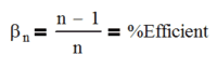
If we have a filter with a beta value of 5, it would be displayed as β5 and would have efficiency of (5-1)/5 or 80%. Note that there is some diminishing point of return. A beta of 1000 is only 0.9% better than a filter with a beta of 100. Some filters are classified as absolute indicating that the beta value is roughly infinite. Keep this in mind when selecting a filter because as the beta value goes up, so does cost.
Filter Location
Many people have very strong opinions on filter placement. We will discuss the pros and cons of each. There are generally three places to install a filter:
- On the suction line
- Directly after the pump
- On the return line
First off, we need to accept that all oil coming from the manufacturer and pumped into our clean reservoir is dirty oil. Yes, I cringed too, but it is true. All this oil needs to be filtered from the first hour of run time. This is why it is important to run the system at low / no pressure so that the pump can turn the oil in the reservoir over 3 to 5 times. If I have a 20 gal tank and a 5 gpm pump, I would need to run the system for 20 minutes before increasing pressure. (20gal / 5gpm*5 = 20 min)
Suction Line
It is popular to put a pump directly on the suction line so that all oil going into the pump is clean. I don’t like it here because you are putting resistance to the flow going into your pump and can cause something called cavitation. If the pump is not getting the oil it needs, it will create a lot of heat. This heat is enough to boil the oil (locally) and ruin a pump very fast. So if you have a dirty filter your pump is going to cavitate quickly unless you are changing that filter very often. One thing that can help is having your hydraulic tank located above your pump. This increases the pressure on the suction line. I highly recommend that you take specific caution when putting a filter on the suction line.
Directly After the Pump
Also known as a high pressure filter, these filters are located right after your pump. I don’t recommend this either for three reasons. First, you’ve already sent the dirty particles through the pump so they will probably move easily through the rest of the system. Second, a dirty filter can lead to less pressure available and the return of particles to the system that have been previously filtered out. Finally, they cost more. Your canister now has to withstand 3000-5000 psi so it’s going to be a very thick wall. The filter’s membranes will have to be thicker and stronger to handle the pressure. This all leads to more cost.
Return Line
My personal preference is to always put it on the return line. But that is just what it is, a preference. I came to this decision after being a “suction line guy” for many years. This changed when I learned that the particles that cause the most problems are the ones ingested by actuators with cylinders being the leading culprit. As a cylinder retracts, they have a nice oily wet rod that is attracting all sorts of dust and then it sucks it back in. Now a lot of that gets wiped off, but many small particles come back in the 5 to 20 micron range that are hazardous to the pump and other components. So I am ingesting millions of these brand new particles with every stroke. With a return filter, they go right to the filter at a low pressure and stay there.
With a return or high pressure filter, it is necessary to have a clean tank when commissioning the system. I just run the system through at no pressure so that the oil cleans up before I really ever use it.
Conclusion
This article should give you insights into the four major components and why each one is important. It will also give you the basics of design criteria and things to consider when designing your hydraulic system.