

If you have ever used a pneumatic or air cylinder, you know that they only have 2 positions: fully retracted or fully extended. There is no middle ground. In fact, due to the compressibility of air, the position will change under varying loads. Most designs take this into account, but what if you REALLY needed to hold a position in the middle. Is there a solution?
A pneumatic cylinder can hold a center position if it is used in conjunction with a hydraulic cylinder. Because hydraulic fluid is incompressible, the hydraulic cylinder can positively lock the rod in place while the pneumatic cylinder produces the motion.
Series Application
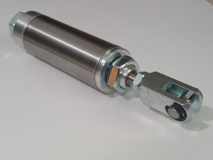
If your application can support a long cylinder configuration, use a series configuration. This will consist of a pneumatic cylinder with the rod co-axially connected to a double rod hydraulic cylinder. The other rod will be connected to the work piece.
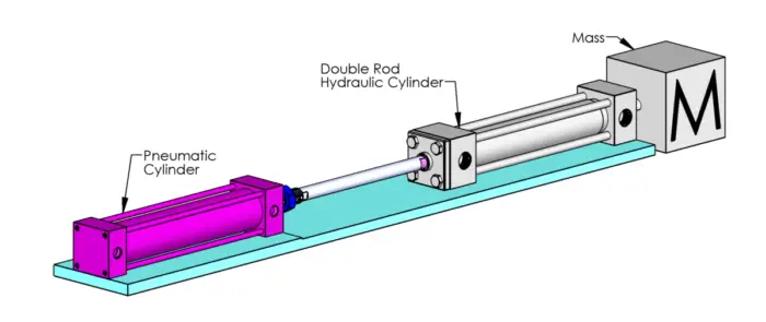
As the pneumatic cylinder strokes, the hydraulic cylinder will also stroke. This will move fluid from one side of the cylinder to the other. When the desired position is reached, a valve can activate to cut off this flow and lock the cylinder in place.
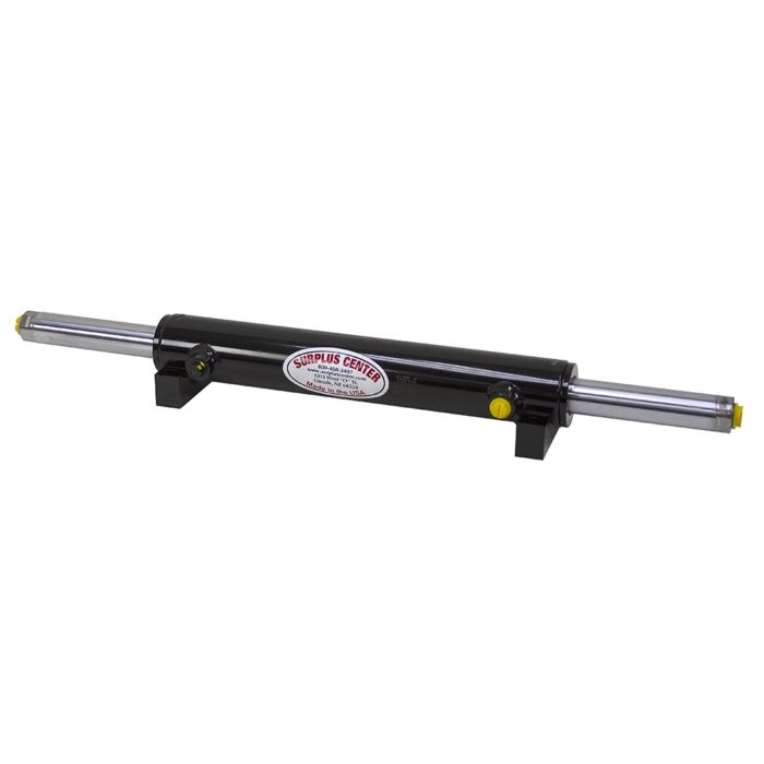
A double rod cylinder is the recommended type because there is an equal area of fluid on each side making it a constant volume of hydraulic oil in the cylinder at all times. This means that as the cylinder is stroked, oil moves from one side of the cylinder to the other. A locking valve can be added between the ports, but no other hydraulic equipment is needed like a reservoir or pump. Simplicity is key for this design!
Since one rod is feeding into the other. This makes for a very long assembly and as a result, buckling may become an issue. But don’t fear, the two bases of the cylinders do not move relative to each other so you can design a structure to support them that can handle the buckling load. And as a bonus, you can mount the cylinder either from the end or as a trunion, which will reduce the length and therefore the tendency to buckle.
Parallel Application
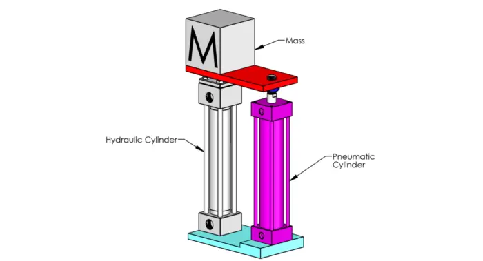
So if you are tight on space, having the hydraulic and pneumatic cylinders side by side may be the way to go. This decreases the length, but increases the design complexity in several ways; more hydraulic components and difficulty providing motion.
More Hydraulic Components
Most likely the switch from series to parallel will change the hydraulic cylinder from double rod to single rod. This means that the area on each side of the cylinder is different and we will need a place to store this extra oil when the cylinder is retracted. Now you need a reservoir.
When moving, both lines will need to join together to feed into the reservoir. To prevent trapped air, the reservoir should be mounted higher than the cylinder. To lock the lines, you can block the line to the reservoir, but I wouldn’t do that. Because of entrapped air and temperature differences, you could get movement. A better way is to use pilot operated check valves or a counterbalance valve on each port.
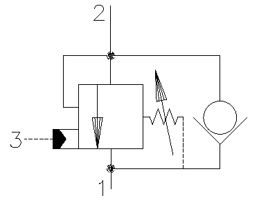
You can also use solenoid operated load holding as well. Please note that we have now increased from one holding valve to two and added a reservoir.
Structural Considerations
Since the cylinders are side by side, you can do one of three things:
- Pneumatic cylinder in line with the load
- Hydraulic cylinder in line with the load
- Neither cylinder in line with the load
There are pros and cons with each of these configurations.
Pneumatic Cylinder in Line with the Load
If the pneumatic cylinder is in line with the load, it will be difficult to hold accurate positioning because the supporting structures may flex. The forces will flow through the hydraulic cylinder in a C shaped configuration. If the hydraulic cylinder is mounted as fixed on each end, the cylinder rod will have to support not only the load, but also the moment caused by the offset.
If the cylinder is free on each end, the structure will need to carry this moment on each end. It is recommended only to use this case when the load is about the same as what the pneumatic cylinder can produce and the other cylinder just hold position.
Hydraulic Cylinder in Line with the Load
It is most likely a better design to have the hydraulic cylinder in line with the load. When holding, the moment is removed and a higher load can be sustained with little stress on the structures. This configuration is definitely preferred if the device is moved unloaded into position, locked and then loaded.
Note that your offset moment load still exists, but on the pneumatic cylinder. I would highly recommend that you design your structures to handle this and put pivoting joints on each end of the cylinder.
Neither Cylinder in Line with the Load
You may find that it is beneficial to split the difference. That perfectly all right, just make sure that you are handling the moment load and no unintended motion will occur.
Controls
Adding a hydraulic control locking cylinder changes the dynamics of the system. First of all, it will slow the system down, but that’s not necessarily a bad thing. Most of the time, we will meter out the air anyway, so we can just remove that from the pneumatics. If need be, we could add a needle valve or flow control in the hydraulic circuit.
(I’m curious to see if in a parallel configuration you could meter in and out of the reservoir after the work ports have combined. If there is no air in the system, it might work, but I’ve never tried it. If it doesn’t work, you can meter out of each cylinder port. Let me know your thoughts below in the comments.)

Second, you can use electronic positioning sensors like an LVDT to help control the system. Combining a position sensor with a process controller and a proportional hydraulic valve, you can slow the cylinder down at it comes to the end of the stroke or the position you want. The sky is the limit.
Summary
With a little innovation, you can do what was once thought impossible: you can hold a pneumatic cylinder midstroke and it won’t move, even under changing load.
If you try to do this, please comment below. I’d really like to see the applications and know what challenges you had.